

 PDF
PDF ePub
ePub Citation
 Print
Print


INTRODUCTION
Provisional restoration is an important step for successful prosthetic treatment. In particular, the provisional restoration protects the prepared teeth, roots, position stability, occlusal function, and margin from oral bacteria and external pressure. Therefore, during the manufacturing process, it is necessary to secure safety of provisional restoration and ensure that it is harmless to the human body, in manufacturing it.12
Provisional restorations are generally produced from self-polymerizing resin (polymethyl methacrylate resin). The resin is made by mixing polymer and monomer and a small portion of unpolymerized monomer is drawn in the course of polymerization. Provisional restoration reduces mechanical impact, triggers volume instability, and may cause allergy or inflammation of the oral mucosa due to biological influence. 134 Accuracy of the provisional restoration varies according to technical proficiency of the resin.
Currently, stable provisional restorations can be designed and manufactured by applying chair-side computer-aided design/computer-aided machine (CAD/CAM) approach to achieve improved accuracy.15 Dental CAD/CAM system, consisting of scanner, CAD program, and CAM program, leads to simplified production process.6
The CAM program can be applied to subtractive manufacturing or additive manufacturing. Because subtractive manufacturing adopts a milling-only block, it can produce equivalent restorations and reduce error in the restorations generated in dental crafting. In many cases in dentistry, provisional restorations are produced through subtractive manufacturing. However, this approach is material-intensive, and detailed representation capability varies according to diameter of the milling bur. In addition, vibration during milling can influence the degree of precision.78 Therefore, dentists have shifted their focus to additive manufacturing to overcome this disadvantage.
Stereolithography apparatus (SLA) for use in additive manufacturing technique comprises a photo-curable resin and light source. Photo-curable resin remains liquid and provisional restorations are produced under irradiation with ultra-violet (UV) light through layer-by-layer system application.910 Because additive manufacturing accumulates materials and creates solid shapes, it produces no waste and is economical in contrast to subtractive manufacturing.
However, design of restorations by means of subtractive and additive manufacturing through CAD/CAM systems may lead to inaccuracies due to limited generating capabilities.11
Accuracy is important in dental treatment. Production of restorations under CAD/CAM approach requires consistency at every stage and accuracy. Recently, a three-dimensional (3D) program has been used to analyze and evaluate possible errors in crowns made through CAD/CAM process.1213 In particular, 3D analysis can precisely measure an identical point without damaging the samples and allows for both quantitative and qualitative data analyses.
Previous studies have reported accuracy of fixed restorations made by using milling instruments.71415
In contrast, there is little data on accuracy of provisional crowns made through stereolithography apparatus and subtractive technique.
The purpose of this study was to compare differences in trueness and precision (accuracy) of the provisional crowns made by means of stereolithography apparatus and subtractive technique.
The null hypothesis of this study states that there is no difference between the trueness and precision of provisional crowns produced by the two techniques in CAD/CAM method.
MATERIALS AND METHODS
The maxillary master model (Frasaco AG3 GmbH, Tettnang, Germany) was selected for use in the study. The maxillary right first molar (AG-3 ZPVK 16, Frasaco GmbH, Tettnang, Germany) was selected for the abutment. The abutment was manufactured by removing from occlusal height 1.5 mm, axial wall 1.5 mm, and 1.0 mm deep chamfer on the margin.
To prepare the master model, a serial video filming intraoral scanner (CS3600, Carestream, New York, NY, USA) was used to fabricate digital impression in the following sequence: occlusal surface, buccal surface, and lingual surface. Data files were saved in STL (stereolithography) format.
The STL files were uploaded into CAD software (Dent CAD, Delcam PLC, Birmingham, UK) and ideal margin was set. Cement space was set to 30 µm. The most clinical program-generated library crown was applied to performance of the CAD design.
Under CAM processing, complete CAD data were divided into subtractive manufacturing and additive manufacturing.
For subtractive manufacturing, tool path was designated using the CAD design data file, and saved as numerical control (NC) file through the CAM milling program (Hyperdent, Open Mind Technologies AG, Wessling, Germany). The NC file was used to process 11 subtractive crowns (SUBC) from a PMMA block (VipiBlock PMMA, Vipi, Pirassununga, Brazil) using automated five-axis milling machine (DWX-50, Roland DG Corporation, Shizuoka, Japan).
For additive manufacturing, position from the CAD design data file was assigned by using a 3D printer program (ZENITH Z512, Dentis, Daegu, Korea). Angle of the crown was set as 180° and support was allowed to occur on the occlusal surfaces, with care to avoid the margin. Default values of the resin support were set as follows: bottom size, 2.0 mm; thickness, 0.7 mm; and end-point size, 0.6 mm. PMMA-only liquid (Zmd1000B, Dentis) containing oligomerbased photopolymer resin was poured, and 11 Stereolithography Apparatus crowns (SLAC) were printed through stereolithography apparatus (SLA) printer (Zenith U, Dentis). The crowns were washed for 2 minutes through immersion in cleaning fluids and photo-cured for 10 minutes by means of UV led curing machine (CURE DEN, Dentis). Subsequently, support was removed from the finished crowns by using a diamond disc, and carefully refined by using a rubber point bur.
For measurement of the accuracy, the outer and inner surfaces of completed provisional crowns were coated with scan spray (Entwickler Nr. 3, Helling GmbH, Heidgraben, Germany). Scan data were sequentially collected by means of blue light scanner (Identica Blue, Medit, Seoul, Korea).
Three Dimension (3D) analysis program (Verify, Geomagic GmbH, Stuttgart, German) was employed to measure the accuracy. Trueness was assessed by superimposition of the scan data and CAD design data for the SLAC and SUBC groups. For analysis of the precision, RMS value was assessed by superimposition of scan data within the group with numerical combination (11C2 = 55).
Root mean square (RMS) was calculated according to the following formula16:
Here, x1,I refers to reference data, x2,I refers to scan data for the different groups, and n denotes measurement point (Geomagic Verify 2015, Geomagic GmbH).
To examine the visual deviation of both surfaces, tolerance limit level for the outer surface was within the range of ± 50 µm and the maximum/minimum critical value was set to ± 150 µm. Tolerance limit level of the inner surface range was set to maximum/minimum value ± 50 µm and the maximum/minimum critical value was set to ± 100 µm.17
The trueness and precision data were compared through quantitative and qualitative analysis by utilizing RMS and color difference mapping. In addition, the outer surface and inner surfaces of the crowns were analyzed by means of digital microscope (KH-7700, Hirox, Hackensack, NJ, USA).
Data were processed using software (IBM Statistical Package for the Social Sciences version 21 software, IBM SPSS Inc., Chicago, IL, USA) and statistical validity was tested based on the mean and standard deviation. Shapiro-Wilk test and Levene test was performed for equal variation. RMS values for the SLAC and SUBC were measured by independent sample t-test, and significant difference was analyzed. Level of Type 1 error was set to 0.05.
RESULTS
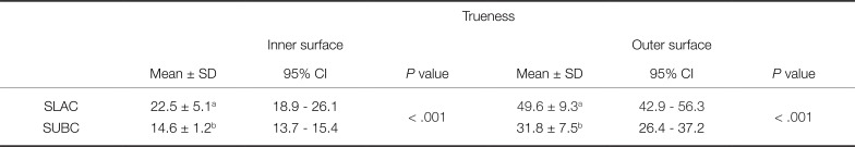
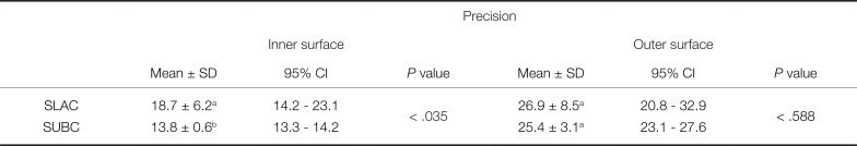
The accuracy of the provisional crowns produced through CAD/CAM system was evaluated. Trueness values for the inner surface and the outer surface presented statistically significant difference based on quantitative analysis (Table 1). Precision analysis result indicated statistically significant difference for the inner surface, whereas no statistically significant difference was observed for the outer surface (Table 2).
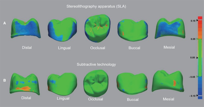
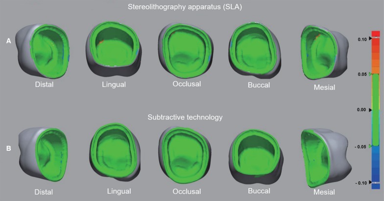
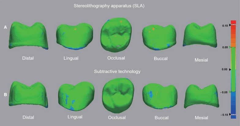
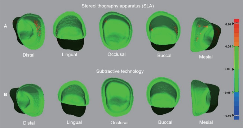
In figures (Fig. 1, Fig. 2, Fig. 3, Fig. 4), green indicates data within the tolerance range based on qualitative analysis; blue indicates negative error, and red indicates positive error. Fig. 1 and Fig. 2 show the trueness; and Fig. 3 and Fig. 4 indicate the precision values for the crowns made by means of SLA and subtractive processing.
Trueness analysis was performed for the outer surface and inner surface, respectively. The outer surface of the SLAC showed negative error for the distal and mesial surfaces, whereas positive error was obtained between the occlusal surface and groove. In contrast, with regard to the SUBC, in general and not for the occlusal region alone, data were within the tolerance range. Both positive error and negative error were obtained for the distal surface (Fig. 1).
Slight positive error was detected in the region between the lingual and the occlusal aspects of the inner surface of the SLAC. Negative error was observed for the distal chamfer margin and margin region. However, slight negative error was observed for the distal chamfer margin in the SUBC group (Fig. 2).
In the precision analysis, negative error was observed in the lower region between the outer buccal and lingual surfaces of the SLAC and SUBC (Fig. 3).
In contrast, positive error was detected in the region between the distal and mesial surfaces of the SLAC. Slight positive error was detected for the lingual surface of the SUBC (Fig. 4).
DISCUSSION
In previous studies, 2D analysis provides only marginal fit of restorations due to limitations in method of measuring the accuracy.81819 Error analysis has become possible through 3D analysis approach for accuracy measurement.
In this study, the trueness and precision of the provisional crowns were investigated by applying methods of evaluating the accuracy of the digitizing device.1213
The accuracy comprises the trueness and precision and its determination involves quantification of systematic error and random error. Thus, the accuracy reflects the trueness of size of measured objects based on reference model and the precision is an indicator of consistency of replicate measurements.1213
The trueness was evaluated by superimposition of scan data from respective samples by setting CAD data as the reference. The precision was measured by superimposition of replicate scan data.
For the provisional crowns fabricated through subtractive technique and stereolithography using the CAD/CAM system, the trueness showed statistically significant difference. Thus, the null hypothesis was rejected. However, the null hypothesis was accepted for the precision of the outer surface, as no statistically significant difference was identified (Table 1 and Table 2).
The trueness analysis demonstrated that the mean, SD, and 95% CI values for the outer and inner surfaces of the SLAC were generally higher than those for the SUBC (Table 1), indicating greater systematic error in the SLAC compared to that in the SUBC. This deviation could be observed by quantifying the trueness by means of color difference map, which revealed group-wise difference in data (Fig. 1 and Fig. 2).
Differences in the trueness value are possibly caused by the different processing methods of CAD/CAM system. The dental milling machine used in this study is a five-axis machine that processes restorations on the x, y, and z axes and a, b axes. However, the SLA is a three-axis machine that operates on the x, y, and z axes. Restoration through the latter shows remarkably low representation compared to that with the former. Moreover, the SLA method employs a photo-curable resin subjected to UV light and involves layer-by-layer accumulation and consequent polymerization. It is possible that this could trigger transformation in the distal-mesial direction.2021
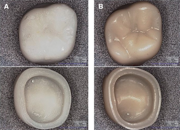
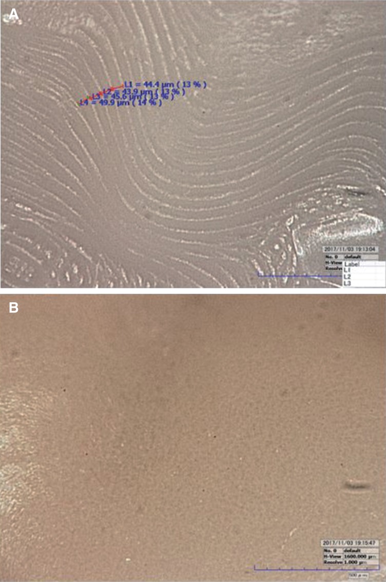
In terms of the precision, the mean, SD, and 95% CI tolerance value for the SLAC were generally larger than those for the SUBC. Moreover, quantitative analysis revealed local positive error in the region between the inner mesial and distal surfaces of the SLAC. Data for the SUBC were within the tolerance range (Table 2). In terms of the precision, the SUBC group showed highly reproducible data relative to that for the SLAC group. Lower reproducibility for the latter is thought to be due to occurrence of random error from light diffraction phenomenon during production of the SLAC (Fig. 3 and Fig. 4).22 When the outer and inner surfaces were observed under digital microscopy, the surface of the SLAC showed poor representation due to formation of layers. In contrast, the SUBC showed planar surface with superior representation of the occlusal surface (Fig. 5 and Fig. 6). In addition, support of the crowns manufactured through SLA was initially removed by using a diamond disc, and remaining parts were carefully refined by using a rubber bur. Nevertheless, traces of the support persisted, which is considered a limitation of 3D printing method. (Fig. 5 and Fig. 6).
Based on our findings, there are various influencing factors in the trueness and precision analysis. However, the accuracy of restorations produced through SLA was inferior to that through subtractive technology, which implies that the accuracy of restorations through CAD/CAM system may influence the marginal fit and internal fit. Moreover, in the trueness analysis, negative errors were observed for the outer surface of the SLAC. Thus, the SLAC may exert effects on the adjacent teeth or contact points. Further studies should be performed to produce various abutments and bridge prostheses, and compare and evaluate the accuracy.
The limitations of this study include the use of a blue light scanner, which involves absence of contact with the crowns during the accuracy measurement. Despite equal coating with the scan spray, its use may result in errors. Moreover, the dental restorations may be limited in terms of clinical application because the experiment employed only the maxillary first molar.
CONCLUSION
For the provisional crowns under CAD/CAM processing, the crown through subtractive processing was superior in terms of the trueness and precision compared to that through stereolithography. For the SLAC, the accuracy of the outer surface and the inner surface layers may be lowered by error. Therefore, it is considered more appropriate to produce the crowns through subtractive processing than stereolithography.
 XML Download