

 PDF
PDF ePub
ePub Citation
 Print
Print


INTRODUCTION
The ceramic veneer restoration around an anterior area has recently attracted attention owing to the increased demand for better esthetics and reduced psychological burden of tooth removal. Ceramic veneers have been an area of focus in the restoration of dental esthetics.123
Among the different types of materials used for such esthetics, lithium disilicate glass matrix ceramics have been widely used owing to their superior appearance, mechanical characteristics, adhesive cementation, and adequate marginal adaptation.4 Lithium disilicate ceramic restorations are manufactured by initially shaping a pattern, and then applying heat pressing to a ceramic ingot.5 Therefore, the state of the pattern is thought to be one of the important factors affecting the quality of ceramic veneers after heat pressing.
Patterns applied for lithium disilicate ceramic veneers have thus far been manufactured using a traditional free-hand wax-up method, in which the wax is carved by the dental technician. Such wax has a high coefficient of thermal expansion, and shrinks by 0.4% when carving a wax pattern and by 0.2% during the burnout.56 In addition, the skills of those manufacturing the wax patterns influence their fit, particularly the fit of the final ceramic veneer, which can be problematic.
A computer-aided design and computer-aided machining (CAD/CAM) system has been introduced and widely used for manufacturing patterns for lithium disilicate ceramic restoration.6 Additive and subtractive manufacturing methods are used in the creation of patterns using a CAD/CAM system.7
Additive manufacturing, patterns are often manufactured using a micro-stereolithography apparatus (Micro-SLA system). The photo-curable resin used for this system is generally a mixture of an oligomer, a monomer, and a photo-initiator, and has lower polymerization shrinkage and superior reproduction.8 In the actual pattern manufacturing, a prototype pattern is achieved by accumulating resins with thicknesses of 0.025 – 0.05 mm for each layer, and continuously laminating at a point unit through UV irradiation on the surface of a photopolymer liquid.
However, with subtractive manufacturing, materials in a wax block form are cut and processed to manufacture the patterns. A five-axis milling machine is often used to manufacture veneer patterns. A five-axis milling machine can be freely processed beneath the cut and has the advantage of high processing precision, allowing the milling bur to approach the processed parts in rectangular directions.
Fit is a very important aspect for a ceramic veneer to function over a long period in an oral cavity. If the fit of a ceramic veneer is poor, certain problems, including fracture of the restoration, an early elimination and even esthetic degradation from peripheral stains, may occur.3910
The marginal discrepancy between the prosthesis and abutment is usually measured for the fit of a ceramic veneer.311 There have been many studies on the marginal fit of general fixed prostheses. However, only a few studies investigated the marginal fit of ceramic veneers manufactured by CAD/CAM system. Moreover, few studies are about the differences in marginal fit depending on the application of additive or subtractive manufacturing, both of which are used in a CAD/CAM system, and on the use of a traditional free-hand wax-up method.
Therefore, the purpose of this study was to comparatively analyze the differences in the marginal discrepancies of ceramic veneers manufactured using additive and subtractive processing technologies of a CAD/CAM system, as well as a traditional free-hand wax-up method.
The null hypothesis of this study is that there are no differences in the marginal discrepancies of ceramic veneers based on the different pattern manufacturing methods applied.
Go to : 
MATERIALS AND METHODS
A maxillary left incisor (Model PE-PRO 001, Nissin Dental products, Inc., Kyoto, Japan) model was prepared to manufacture the ceramic veneers. To manufacture the study models, an impression was then made using both light-body (Aquasil Ultra XLV Regular Set, Dentsply Detrey GmbH, Konstanz, Germany) and heavy-body (Aquasil Ultra Rigid Regular Set, Dentsply Detrey GmbH, Konstanz, Germany) silicone (Fig. 1).
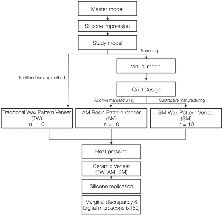
To manufacture patterns using a traditional free-hand wax-up method, a two-layer die spacer (Nice Fit, Shofu, Inc., Kyoto, Japan) was applied to the surface of type IV study models, where the thickness of the die spacer on the surface was about 20 µm. An adequate outward shape was then carved through a free-hand wax-up technique using modeling wax (Geo Wax, Renfert GmbH, Hilzingen, Germany). A total of ten wax-pattern veneers were acquired, and a single skillful experimenter conducted the carving for consistency.
Meanwhile, to manufacture the patterns using additive and subtractive manufacturing methods, working models were scanned using a lab scanner (Identica Blue, Medit, Seoul, Korea). From the scanned stereolithography, an STL file was used to design the outer shape of the upper-left incisor using the CAD software (Exocad DentalCAD, Exocad GmbH, Darmstadt, Germany). The cement spacing was set to 20 µm.
For the additive manufacturing, 3-D printing was conducted by applying an STL file to a µ-SLA (ProJet 1200, 3D systems, Rock Hill, SC, USA) system.412 During the printing process, a laminate veneer was produced through UV irradiation of a polymerized plastic cartridge resin (VisiJet FTX Green, 3D systems, Rock Hill, SC, USA). In addition, three patterns were allowed to be arranged on a single platform.13 Then, the resin pattern of the laminate veneer was further hardened using a UV lamp for 10 minutes.
For the subtractive manufacturing, an STL file was applied to a dental CAM software program (Hyperdent, Open Mind Technologies AG, Wessling, Germany) to calculate the tool path. The results of the calculated tool path were stored in the numerical control (NC) data. A total of ten wax patterns were acquired through milling on a five-axis milling device (DWX-50, Roland DG Corporation, Shizuoka, Japan) using the stored NC file. In addition, a wax block (Vipi Block wax, Vipi, Pirassununga, Brazil) dedicated to milling applications was used as the milling material.
Vacuum investing of a total 30 of pattern samples manufactured using the three methods was conducted with phosphate-bonded investments (Prime vest HS, BK Giulini, Ludwigshafen, Germany), and the samples were hardened for 1 hour, as suggested by the manufacturer. The investment ring was cast at 850℃ for 1 hour and 20 minutes. A ceramic ingot (IPS e.max Press LT, Ivoclar Vivadent, Schaan, Liechtenstein) was injected into the inlet of the cast investment ring. After being combined with a plunger, heat pressing was applied in a vacuum porcelain furnace (EP 600, Ivoclar Vivadent, Schaan, Liechtenstein) at 850℃ for 18 minutes. The investment ring was slowly cooled to room temperature. After removal of the investment, the inner silicon dioxide film and any impurities were eliminated by applying a sand blasting method with 4 bars into the inner part of the shaped ceramic veneer using a glass bead consisting of 50 µm particles.
A silicone replica technique was used to measure the marginal discrepancy. To this end, the master model fitting was conducted by injecting light-body silicone (Aquasil Ultra XLV Regular Set, Dentsply Detrey GmbH, Konstanz, Germany) into the inner surface of the ceramic veneer. Then, a light-body silicone film layer was manufactured by applying a finger pressure of about 20 N. This layer was then fixed using heavy body silicone (Aquasil Ultra Rigid Regular Set, Dentsply Detrey GmbH, Konstanz, Germany).12
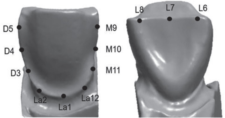
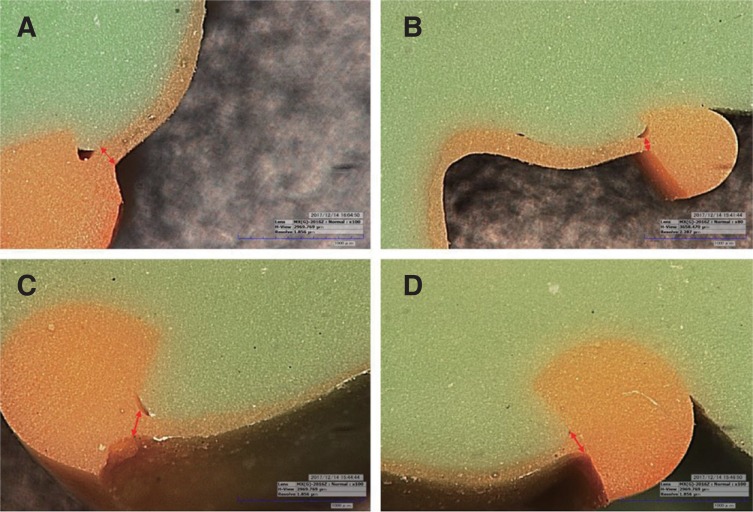
Twelve areas were measured, which were designated and cross-sectioned by dividing the silicone replica mold into buccal, lingual, distal, and mesial areas. Finally, the marginal discrepancy was measured using a digital microscope (KH-7700, Hirox, Hackensack, NJ, USA) (Fig. 2, Fig. 3, Fig. 4).
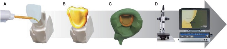 | Fig. 2Silicone replica technique processing for measurement of marginal discrepancy: (A) silicone injection (B) silicone replica inner surface (C) fixed with medium body silicone (D) measurement with digital microscope.
|
A statistical analysis of the measurements was conducted using statistical software (IBM Statistics for Windows, v23.0, IBM Corp). To test the regularity of the marginal discrepancy in the measured areas, depending on manufacturing methods, Shapiro-Wilk and Kolmogorov-Smirnov tests were conducted; however, the results did not indicate a normal distribution (P < .05). Therefore, a nonparametric Kruskal-Wallis test and a Mann-Whitney U Test were conducted, adjusting the significance using the Bonferroni method, which is an ex-post analysis technique.
Go to :
RESULTS
The marginal discrepancy results are shown in Table 1 to Table 5. The means, standard deviations, maxima, minima, medians, and confidence intervals are shown in the tables, along with the statistical significance of each measurement.
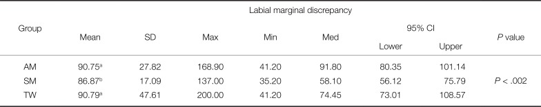
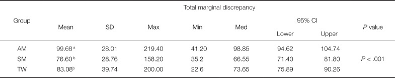
Table 1
Mean, standard deviation (SD), maximum (Max), minimum (Min), median (Med), confidence interval (CI) of descriptive statistics of lingual marginal discrepancies in ceramic veneers (unit: µm)
![]()
Table 5
Mean, standard deviation (SD), maximum (Max), minimum (Min), median (Med), confidence interval (CI) of total marginal discrepancies in ceramic veneers (unit: µm)
![]()
As shown in Table 1, the TW group had the largest mean value of the labial discrepancy, 90.79 ± 47.61 µm, whereas SM group had the lowest value, 65.96 ± 26.34 µm, suggesting a significant difference in the labial discrepancies between the two groups (P < .002).
As shown in Table 2, the AM group had the largest mean value of distal discrepancy, 86.87 ± 17.09 µm, whereas the TW group had lowest value, 63.93 ± 33.84 µm, suggesting a significant difference in the distal discrepancies between the two groups (P < .001)
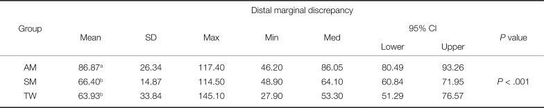
Table 2
Mean, standard deviation (SD), maximum (Max), minimum (Min), median (Med), confidence interval (CI) of descriptive statistics of distal marginal discrepancies in ceramic veneers (unit: µm)
![]()
As shown in Table 3, the AM group had the largest mean value of mesial discrepancy, 101.79 ± 25.09 µm, whereas the SM group had the lowest value, 81.12 ± 29.43 µm, suggesting a significant difference in the mesial discrepancies between the two groups (P < .019)

Table 3
Mean, standard deviation (SD), maximum (Max), minimum (Min), median (Med), confidence interval (CI) of descriptive statistics of mesial marginal discrepancies in ceramic veneers (unit: µm)
![]()
As shown in Table 4, the AM group had the largest mean value of lingual discrepancy, 119.32 ± 29.46 µm, whereas the SM group had the lowest value, 76.60 ± 28.76 µm, suggesting a significant difference in the lingual discrepancies between the two groups (P < .001)
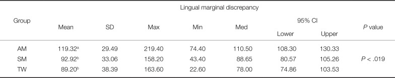
Table 4
Mean, standard deviation (SD), maximum (Max), minimum (Min), median (Med), confidence interval (CI) of descriptive statistics of lingual marginal discrepancies in ceramic veneers (unit: µm)
![]()
Table 5 shows the total mean ± standard deviation of the marginal discrepancies. The AM group had the largest value at 99.68 ± 28.01 µm, followed by the TW group at 83.08 ± 39.74 µm, and the SM group at 76.60 ± 28.76 µm. The results indicate statistically significant differences among these groups (P < .001).
Go to :
DISCUSSION
In dental science, the use of digital imaging through a CAD/CAM system has recently increased. A shift from analogue to digital-based methods has also occurred in medical treatments as well as the manufacturing of prostheses. As part of this period of transition, the clinical availability of a digital-based method using a CAD/CAM system rather than an analog-based system in the manufacturing of ceramic veneer patterns was examined in the present study.
In this study, the null hypothesis that the marginal fit is unaffected by the processing method used for generating patterns for ceramic veneers was rejected (P < .05).
A total of 20 ceramic veneers manufactured using additive and subtractive techniques were used as the experimental group, and for a comparison with the experimental manufacturing group, ten ceramic veneers of the same form were created as the control group using a traditional free-hand wax-up method. The marginal discrepancy was measured on a total of 360 points (12 points for each sample), thereby increasing the reliability of the 30 samples.
This study used a silicone replica technique to measure the marginal discrepancy. This silicone replica technique, which measures the thickness of the inner surface by filling light-body silicone into a prosthesis, is widely used in measurements of marginal discrepancy because it can prevent damage to the prosthesis and the occurrence of an abutment.1214
There has been no consensus on the values or criteria of the fit of a prosthesis clinically allowed by the dental community. Although the American Dental Association states in ADA No. 815 that the proper fit of a fixed prosthesis ranges from 25 to 40 µm, it is impossible to reach such a goal using current manufacturing technology. Sulaiman suggested 100 µm16 and McLean and von Fraunhofer suggested 120 µm for a clinically proper peripheral fit of a fixed prosthesis,17 whereas Vojdani proposed a range of 200 to 300 µm.18 Notwithstanding, many researchers have recently reported that a range of less than 120 µm is proper and can be clinically accepted, and thus the present study suggests that a discrepancy of less than 120 µm is clinically allowable.
As shown in Table 5, the mean value of the marginal discrepancy of the SM group was superior to those of the AM and LW groups, with statistical significance (P < .001). Notwithstanding, the mean values of the three groups, as well as the marginal discrepancies in the four measured areas, buccal, lingual, distal, and mesial, were within the allowable limit of less than 120 µm (Table 1, Table 2, Table 3, Table 4).
The AM and SM groups were uniformly manufactured using an automated system. However, the difference between the AM and SM groups varied based on the axis applied. For the SM group, a five-axis milling machine was used, which has a complex form because a straight feeding axis for the x-, y-, and z-axis and two rotation feed axes of a and b were added; in addition, it was able to achieve more precise cutting in areas under the cut.19 The AM group was manufactured using three-axis 3D printing technology, which is less accurate than a five-axis machine, and was therefore thought to affect the marginal discrepancy.20 In addition, a layering error, which typically appears during the lamination process, can occur. For this reason, the optical diffraction increased as the UV source irradiated a wide area of resin through a mirror.12 Such a pattern also appeared similarly in preliminary studies. Therefore, the fit of the resin is not only reduced, but the fit of the final completed ceramic veneer can vary owing to shrinkage of the polymerized resin.
Hence, a five-axis milling machine is recommended for manufacturing ceramic veneer patterns. Although many factors are thought to have an effect on the findings, more studies on Micro SLA are required in particular because its marginal discrepancy is higher than that of the milling process or the traditional free-hand wax-up method. For the SM group, it is believed that the existing wax-up technique can be replaced with current digital processing methods.
However, this study also has certain limitations. First, although the measurement of a silicone replica technique is known to have high accuracy and reliability, it may be difficult to exclude the shrinkage and expansion of the silicone. Second, the abutment used in this study is a standard die but may be clinically improper. Third, although a skillful researcher tried to maintain consistency when applying the traditional wax-up method, there is a limit in controlling the experimental error.
In further studies, other forms of abutments should be applied; in particular, a clinical evaluation of the inside of a patient's oral cavity should be additionally conducted.
Go to :
CONCLUSION
Despite various advantages of dental technologies, the most important aspect is the completion of the manufactured device. The SM veneer showed better values than AM and TW veneers. Although the marginal discrepancy of the ceramic veneers manufactured in this study varied significantly according to the manufacturing methods used, the range, which was less than 120 µm, is suitable for clinical applications.
Go to :
 XML Download