

 PDF
PDF ePub
ePub Citation
 Print
Print


INTRODUCTION
Spinal cord stimulation (SCS) is a common therapeutic technique for treating medically refractory neuropathic back and other limb pain syndromes. The common technique used historically for placing SCS leads required direct interaction with the patient, combining a sedative anesthetic technique and awakening the patient during the surgery. This approach required the patient to be alert enough to respond to sensations generated by the stimulation and directions from the surgical team. However, these responses have been demonstrated to be unreliable or misleading for several reasons: 1) the potential wide variety of pain responses of patients during changing levels of sedation, 2) the variable responses to anesthetics, 3) the variable array of pain distributions, 4) the often inadequate ability of the patient to differentiate their pain syndrome from the effects of surgery or the feeling of the stimulation at the time of testing, 5) positional changes due to spinal cord (cord) movement, and 6) cord location relative to the lead (the actual device containing all of the electrodes or contacts) in only the prone position.12345 Newer multicontact designs of paddle leads have improved the ability to capture pain relief even when the lead has not been ideally positioned or moves slightly during surgery. However, these new designs still require the lead to be placed in an appropriate mediolateral position relative to the specific morphology of the dorsal column (DC) fibers and entering dorsal nerve roots. The center of the cord may be more than 2 mm from the canal center in 40% of patients,56 especially when using fluoroscopy due to parallax and visual-alignment errors. The cord itself may also be rotated slightly, making one side of the DC closer to the electrode even if it is located perfectly along the midline.
It is critical that leads be placed at the appropriate cranial-caudal spine level in order to maximize the desired pain coverage. However, the cranial-caudal position is easier to locate given the use of trial lead information, the known segmental dermatomal distributions, and the length of the leads that can cover two or three vertebral levels. As a rule of thumb, lower back coverage is best obtained at T8, buttock and leg coverage at T9 or T10, and foot coverage below T10. Nonetheless, mediolateral electrode optimization remains very important for maintaining coverage once the lead is covered in an unknown amount of fibrosis, which changes the electrical characteristics of the surrounding tissue to an extent that often requires reprogramming.
Additionally, both sedative and awake procedures in prone patients have notable risks of complications. The risk of losing airway patency is high in prone patients who are overse-dated. More sedation is typically needed for tunneling and the creation of a pocket for the implantable pulse generator if the patient has only been sedated for the initial incision and dissection to the epidural space. Determining the optimal trade-off between patient comfort and oversedation is not always straightforward, and in rare situations the surgical wound will need to be packed on an emergency basis and the patient immediately returned to a supine position to allow intubation. Some data from analyses of the closed claims data of anesthesia cases suggest that the risk of severe respiratory depression with brain damage or even death could be as high as 6%.7
The use of neurophysiological mapping techniques allows these procedures to be performed under general anesthesia, which eliminates all of the above concerns. Two primary mapping techniques are currently used when placing SCS leads. The first technique is called compound muscle action potential (CMAP) activation, and is based on the antidromic activation of alpha motor neurons (MNs) (light green arrows in Fig. 1) through stimulation of the large Ia fibers of the DC.89101112131415 This stimulation is applied via the electrode itself, and antidromically depolarizes the MN to induce a CMAP in the muscle innervated by that motor unit (Fig. 2). It is important to note that the stimulation needed to generate the CMAP response typically has a slightly higher intensity than that normally used postsurgery for pain therapy. This increased stimulation intensity is necessary to overcome the effects of anesthesia at the MN synapse and because these Ia fibers only constitute over 4,000 afferent synapses to the MN,16 while modeling and neurophysiological collision studies have demonstrated that the stimulation is in the DCs.8
 | Fig. 1Graphical representation of the activated pathway during the antidromic CMAP technique. The SCS lead stimulates the dorsal column at an intensity that is high enough to activate sufficient large Ia fibers to antidromically excite the alpha motor neurons and generate a CMAP in the muscle. It should be noted that stimulation level is much lower during normal pain therapy, and so no motor activation occurs.8 CMAP: compound muscle action potential, SCS: spinal cord stimulation.
|
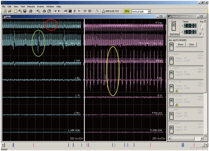 | Fig. 2Three different waveforms, two of which are artifacts. The response in the red circle is an artifact from the stimulation device. The response in the green circle is from an EKG artifact. The responses in the yellow circle are compound muscle action potential generated by the antidromic activation of the alpha motor neuron pool for this muscle group.
|
The second technique is called a collision technique, and is based on the collision of opposing action potentials (APs) in the DC of the spinal cord. In this technique, the intensityintensities of cortical standard somatosensory evoked potentials (SSEPs) intensityintensitiesare used as an indicator of laterality.17 This technique is based on SSEPs being generated via time-locked stimulus averaging, where any signal that is not time locked will not only act as noise but will also collide within the spinal cord, thereby canceling the APs generated by the SSEP stimulation at the median/ulnar or posterior tibial nerves. These two features cause a reduction in the cortical SSEP intensity on the side that is being affected by the non-time-locked SCS. While both techniques are utilized, a recent study comparing them suggested that the CMAP technique was more reliable and robust.13
Go to : 
METHODS
CMAP technique
Recording
As stated above, the CMAP technique activates lower MNs via antidromic APs generated in the DC Ia fibers. It should be appreciated that these Ia fibers are also generally utilized for traditional stimulation paresthesias and pain relief.18 Thus, the CMAP activation occurs via the same fibers that would be used clinically, and the myotomal activation generally overlaps with the dermatomal mapping that is performed when programming the device for clinical applications.
The CMAP technique utilizes bilateral, simultaneous freerunning EMG (Fig. 2) activity recorded via two subdermal needles inserted into muscles related to the spinal segmental levels of the desired SCS lead placement. Muscles that are innervated by motor units above and below the desired segmental levels are also used to assure proper coverage and activity due to myotomal variations.19 The electrodes are placed in the muscle bellies 1–2 cm apart. The cervical leads are used to monitor the following muscles: 1) trapezius, 2) deltoid, 3) biceps brachii, 4) triceps, 5) flexor carpi ulnaris, 6) extensor carpi ulnaris, 7) abductor pollicis brevis, 8) abductor digiti minimi, and 9) gastrocnemius. The thoracic leads are used to monitor the following muscles: 1) iliopsoas/adductor longus, 2) vastus medialis, 3) tibialis anterior, 4) gastrocnemius (and/or soleus), 5) abductor hallucis, 6) paraspinal (rhomboid and/or erector spinae and/or trapezius; the ultimate decisions about which muscles are evaluated depend on the level and region of the pain), and 7) rectus abdominis (or sometimes the external oblique, depending on the amount of adipose tissue).
Needle leads are taped to the skin with either silk tape or Tegaderm® (3M, St. Paul, MN, USA), and the wires are secured with a piece of silk tape or Tegaderm® at 5–10 cm from the needle to provide strain relief. All wires are run to the base of the operating table and connected to the amplifier of the EMG recording system. A ground electrode is placed on the lateral thigh or shoulder depending on whether a thoracic or cervical case is being performed. The thoracic SCS leads are only used to examine the lower limbs, while the cervical leads are used to examine muscles of both the upper and lower extremities.
Test stimulation application
This method has been described elsewhere, yet a review in this manuscript is warrented.8 Stimulation is applied via the SCS electrodes (Fig. 3). The outer margins or corners of the SCS lead are activated initially to determine the orientation of the lead relative to the cord. In some cases the center of the lead is also activated or larger bipolar configurations are used to generate the CMAP. The actual electrode pairs that are activated depend on the type of lead being used. Stimulation is applied by connecting the lead directly to the manufacturer's screening device via special screening cables that are also provided by the manufacturer, and so no special equipment is needed. Impedances are measured to ensure that the lead electrodes are in good contact with the dura.
 | Fig. 3Graphical representation of the stimulation paradigms used for different lead types. The first lead on the left shows the sequence used, with the leftmost electrode pair being the first tested and then sequentially going around the leads testing each electrode pair in a cranial-to-caudal/left-to-right order. A similar pattern is used for the other electrodes.
|
The initial stimulation testing parameters used in the several studies that have been published on this technique vary from very low frequency (e.g., 5 Hz) with longer pulses to higher frequencies and pulses of variable length (Table 1 for references and specific parameters). Although lower frequencies may ultimately drive the MN adequately for testing, using the frequencies and pulse widths that are close to the ranges actually applied clinically for pain relief may be more reliable for identifying the fibers that are ultimately related to the paresthesias used clinically. After performing initial stimulation testing, the intensity is slowly increased in 0.5-V or 0.5-mA increments until EMG activity is detected (yellow ellipse in Fig. 2) in any channel. The intensity is slowly increased further in 0.5-V or 0.5-mA increments until one of the following occurs: 1) the stimulator reaches its maximum output, 2) all muscle groups on both sides are activated, or 3) the activation on one side is saturated (Fig. 4), which means that all muscles on one side are firing. It is important to be able to differentiate the noise (a stimulation artifact indicated by the red ellipse in Fig. 2) and EKG artifact (indicated by the green ellipse in Fig. 2) from the actual EMG response (indicated by the yellow circle in Fig. 2). These artifacts are not always obvious and in some cases can obscure smallintensity CMAP signals.
 | Fig. 4Complete activation of all muscles on the right side with no continuous response found on the left side.
|
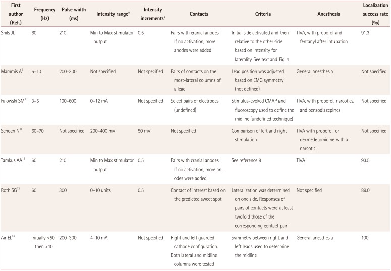
Table 1
Studies that specifically involved the antidromic CMAP technique
| First author (Ref.) | Frequency (Hz) | Pulse width (ms) | Intensity range* | Intensity increments* | Contacts | Criteria | Anesthesia | Localization success rate (%) |
|---|---|---|---|---|---|---|---|---|
| Shils JL8 | 60 | 210 | Min to Max stimulator output | 0.5 | Pairs with cranial anodes. If no activation, more anodes were added | Initial side activated and then relative to the other side based on intensity for laterality. See text and Fig. 4 | TIVA, with propofol and fentanyl after intubation | 91.3 |
| Mammis A9 | 5–10 | 200–300 | Not specified | Not specified | Pairs of contacts on the most-lateral columns of a lead | Lead position was adjusted based on EMG symmetry (not defined) | General anesthesia | Not specified |
| Falowski SM10 | 3–5 | 100–600 | 0–12 mA | Not specified | Select pairs of electrodes (undefined) | Stimulus-evoked CMAP and fluoroscopy used to define the midline (undefined technique) | TIVA, with propofol, narcotics, and benzodiazepines | Not specified |
| Schoen N11 | 60–70 | Not specified | 200–400 mV | 50 mV | Not specified | Comparison of left and right stimulation | TIVA with propofol, or dexmedetomidine with a narcotic | Not specified |
| Tamkus AA12 | 60 | 210 | Min to Max stimulator output | 0.5 | Pairs with cranial anodes. If no activation, more anodes were added | See reference 8 | TIVA | 93.5 |
| Roth SG13 | 60 | 300 | 0–10 units | 0.5 | Contact of interest based on the predicted sweet spot | Lateralization was determined on one side. Responses of pairs of contacts were at least twofold those of the corresponding contact pair | Not specified | 89.0 |
| Air EL14 | Initially >50, then >10 | 200–300 | 4–10 mA | Not specified | Right and left guarded cathode configuration. | Symmetry between right and left leads used to determine the midline | General anesthesia | 100 |
| Both lateral and midline columns were tested |
![]()
Once all of the data are obtained for each electrode pair, a midline is calculated based on the laterality of the initial response and the stimulation intensity required to generate the CMAP on the contralateral side, if it occurs (the red line in Fig. 5 indicates the midline). For example, if the CMAPs from all muscles on the right side are generated and no leftside muscle CMAP activity is noted for a stimulus up to 1.0 mA higher than the level for inducing complete right-side activation, the midline of the cord would be designated so that those electrodes were kept to the right of the DC midline (Fig. 5). However, if the initial CMAP was the tibialis anterior on the left side and a muscle on the right side showed CMAP activity before the occurrence of full left-side activation the line would be drawn through the contact pair with the majority of the midline to the right of the electrode pair. The final condition is when CMAP activity starts together on the left and right sides at the same stimulation intensity. In this situation the midline is drawn so that the contact pairs (one on the left and one on the right) are equidistant from the midline. It is also important to realize that some transient motor activity that can occur during the testing should not be relied upon; instead, only sustained CMAP activity is used to formulate any conclusions, and so it is helpful to wait a short time to ensure that measured signals are sustained.

The usual testing protocol as described above may need to be adjusted in certain situations. These modifications have been described previously, and they are summarized below.8 The output of the screening device might reach its maximum intensity limit, such as that determined by the safety constraints built into each manufacturer's system.8 This situation can occur in one of three ways. First, the output voltage or current limit is reached after EMG activity has been initiated. In this situation there are likely to be sufficient data to continue with the standard protocol. Second, no EMG activity data have been obtained when the limit is reached, in which case the pulse width may be increased slowly until EMG activity is detected, and measurements can commence from other contacts. Third, no EMG activity is recorded when both the intensity and pulse-width limits are reached. When this occurs more anodal electrodes are added and a DC midline evaluation is performed based on this new configuration. The number of anodes is increased rather than cathodes in order to maintain the focality of the stimulation, since the cathode is the driving source electrode. These conditions are more likely to occur in cases where a previously implanted electrode is being repositioned and scar tissue or thickened dura is present. Epidural fat tissue can also contribute to this phenomenon. In rare cases a larger bipole involving the use of additional cathodes and anodes is needed to generate a CMAP, and this should be attempted if necessary.
As mentioned above, different variations of the technique described above have been reported in the literature, but all of them focus on measuring CMAPs in peripheral muscles activated via antidromic Ia fiber activation. Falowski et al.10 utilized stimulation at 3–5 Hz, pulse widths of 100–600 µs, and intensities up to 12 mA. Roth et al.13 utilized stimulation at 60 Hz, pulse widths of 300 µs, and intensities up to 10 V or 10 mA (they only used the term ‘units’ in their paper) during their testing, and looked for and defined a lateralized lead if the EMG intensity on one side were at least twice those on the other side. Mammis et al.9 utilized stimulation at 5–10 Hz and an initial pulse width of 200–300 µs, with pairs of electrodes being used on each column of the lead. Those authors analyzed the symmetry of the EMG intensities and used this information to reposition the electrode and lead accordingly.
Table 1 summarizes the testing parameters and criteria used in this study. In our experience, the absolute intensity of the CMAP and the threshold for generating a CMAP cannot be relied upon since they tend to be influenced by 1) the characteristics of the particular motor unit involved, which may differ between sides, 2) the far-field symmetry of the placement of the recording electrodes, and 3) an asymmetric placement of the recording electrodes in many conditions.
Collision technique
The collision technique17 is based on the SSEP and SCS pathways in the spinal cord being the same and the identical fibers being activated during low-frequency SCS and SSEP testing. Given that these two signals travel in the same fibers, depending on the location of the SCS lead and the side of SSEP testing, collisions will take place that can help to localize the effects of SCS. Similar to the motor technique, the collision technique involves the Ia sensory fibers in the DCs.
Whereas the motor technique relies on CMAP generation via antidromic activation of the Ia fibers, the collision technique is based on detecting changes in the intensity of the cortical SSEP response on each side of the head in relation to the contacts on the SCS lead that are being tested. Given the decussation at the level of the medulla via the internal arcuate fibers, it is the contralateral cortical SSEP that is being evaluated. The SSEP APs follow a course from the peripheral nerve through the dorsal spinal root into the DC and then through the brainstem to the thalamus and then the cortex. The recorded trace is time locked to the stimulation applied at a peripheral nerve, and multiple stimulation triggers are averaged to generate the SSEP responses seen in the cortical trace (Fig. 6). SSEPs need to be averaged so that the true response can be distinguished from the background noise. In contrast, the SCS signal is generated at the spinal cord DC and is not time locked to the SSEP stimulation and the recorded output. These pseudorandom APs (relative to the SSEP stimulation frequency) affect the SSEP-generated APs in one of two ways (Fig. 7): 1) collision can occur in the DC between the orthodromic SSEP generated AP and the antidromic SCS-generated AP that annihilates the SSEP AP (Fig. 6), or 2) multiple non-time-locked APs generated by SCS add noise to the system that prevents the standard recovery times along the SSEP pathway, which in turn reduces the number of SSEP-generated APs either passing a synapse or generating excitatory postsynaptic potentials in the cortex (Fig. 7). Due to the length and firing rates of the SSEP and SCS APs, the first condition plays a much greater role in the reduction of SSEPgenerated APs passing through to the cortex.20 This technique is primarily used for cervical procedures,17 but it has also been applied in thoracic SCS lead placement13 and has produced similar results.
 | Fig. 6Graphical representation of the basis for the SSEP collision technique. On the left side, the SSEP passes through the sensory pathways uninhibited by any external SCS, thus producing a normal cortical SSEP response. On the right side, the SCS blocks the SSEP stimuli from reaching the cortex, resulting in no cortical SSEP response. See the text for more details. SCS: spinal cord stimulation, SSEP: standard somatosensory evoked potential.
|
 | Fig. 7A collision occurs when the SCS-generated antidromic AP and the SSEP-generated orthodromic AP meet at the same point while they are traveling in opposite directions. When this occurs no AP reaches the cortex to generate a response. In some very rare situations the stimuli may be sufficiently out of phase to allow an SSEP AP to pass undisturbed. However, the large difference between the SCS rate and the SSEP stimulation rate makes this condition highly unlikely. AP: action potentials, SCS: spinal cord stimulation, SSEP: standard somatosensory evoked potential.
|
Stimulation
SSEP stimulation is applied at either the median or ulnar nerve for cervical leads and at the posterior tibial nerve for thoracic leads. The actual stimulation point (the point on the spinal cord that is being activated) is determined by the level of the SCS lead. Square-wave pulses with a pulse width of 200 µs are applied at rates varying from 2.1 to 4.1 Hz, and SCS is applied using the manufacturer's testing device at a pulse width of 60 to 300 µs, a frequency of 40 to 60 Hz, and intensity of 0.5–5 mA or 0.5–5 V.1317
Recording
Recording electrodes are placed at the following standard international 10–20 SSEP recording locations: P3, P4, Fz, mastoid for subcortical responses, and Erb's point. The montage is C3'-Fz for the left SSEP and C4'-Fz for the right SSEP,17 with a focus on the cortical responses (N20/P25) since they are the most reliable. SSEPs are averaged for 120–200 trials. Other cortical montages are also possible, such as C4'-C3', C3'-C4', or Cz-Fpz.
Testing
Baseline SSEPs are acquired first, and then the device providing the SCS is turned on at its lowest intensity, and SSEP testing is started using the central electrode contacts. After two SSEP trials performed at a specific SCS intensity, the intensity is increased in 1.0-mA or 1.0-V increments until there is a significant reduction in the SSEP cortical intensity (at least 50%) on one side.17 The intensity is then further increased by 1 mA or 1 V to determine whether or not the effect is bilateral. Several responses are possible: 1) a unilateral reduction, in which case the electrode is placed on the side of the spinal cord contralateral to the cortical SSEP change, 2) a bilateral reduction at the same current or voltage, in which case the electrode is placed along the midline, 3) a reduction in the contralateral cortical SSEP, which is followed by a reduction in the opposite cortical SSEP after increasing the SCS by 1 mA or 1 V, in which case the electrode is placed just away from the midline, or 4) no response, in which case no localizing information can be determined. Table 2 summarizes the published testing procedures and criteria used for determining lateralization with the collision technique.
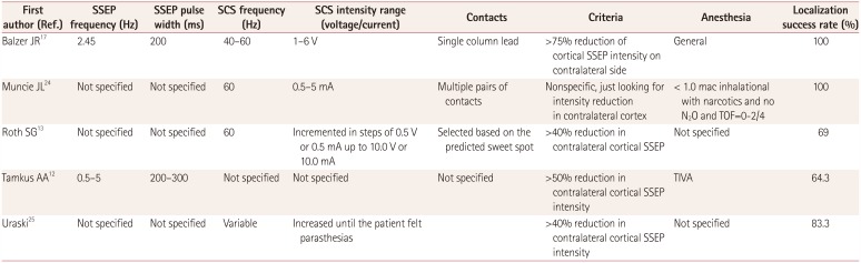
Table 2
Studies that specifically involved the SSEP collision technique
| First author (Ref.) | SSEP frequency (Hz) | SSEP pulse width (ms) | SCS frequency (Hz) | SCS intensity range (voltage/current) | Contacts | Criteria | Anesthesia | Localization success rate (%) |
|---|---|---|---|---|---|---|---|---|
| Balzer JR17 | 2.45 | 200 | 40–60 | 1–6 V | Single column lead | >75% reduction of cortical SSEP intensity on contralateral side | General | 100 |
| Muncie JL24 | Not specified | Not specified | 60 | 0.5–5 mA | Multiple pairs of contacts | Nonspecific, just looking for intensity reduction in contralateral cortex | < 1.0 mac inhalational with narcotics and no N2O and TOF=0–2/4 | 100 |
| Roth SG13 | Not specified | Not specified | 60 | Incremented in steps of 0.5 V or 0.5 mA up to 10.0 V or 10.0 mA | Selected based on the predicted sweet spot | >40% reduction in contralateral cortical SSEP | Not specified | 69 |
| Tamkus AA12 | 0.5–5 | 200–300 | Not specified | Not specified | Not specified | >50% reduction in contralateral cortical SSEP intensity | TIVA | 64.3 |
| Uraski25 | Not specified | Not specified | Variable | Increased until the patient felt parasthesias | >40% reduction in contralateral cortical SSEP intensity | Not specified | 83.3 |
![]()
Go to :
DISCUSSION
SCS leads have historically been surgically placed using a combination of local anesthetics and conscious sedation. Complications associated with this technique include difficult airway management and the need for emergency airway management (requiring the patient to be moved), patient discomfort, and potentially unreliable patient responses due to positioning, surgical discomfort, and general patient anxiety. The ability to implant these electrodes using a general anesthetic technique with intraoperative neurophysiology reduces all of these risks while producing similar (or even improved) results as well as shorter operating times.810
Yingling and Hosobuchi21 were the first to attempt to place SCS leads, in 1986. Their technique utilized antidromic APs and involved recording the APs in a peripheral nerve. They also attempted to record via stimulation over the peripheral nerve and record at the SCS lead, but the obtained responses were not reliable. Their reasoning for this difference between antidromic and orthodromic APs was twofold: 1) due to the closeness of the lead to the nerves, stimulating the spinal cord is more effective than peripheral stimulation over the skin and nerve, and 2) there is more noise in the spinal cord than in peripheral nerves.21 However, their explanation is unlikely to be accurate since it is easy to record both orthodromic and antidromic D-waves in the operating room.22 Instead, their difficulties were probably related to the problem of activating just the large afferents, thereby leading to a moredispersed signal at the spinal cord.
Two studies have compared both the outcome and intraoperative results between the EMG and SSEP collision techniques.12,13 Roth et al.13 investigated 75 implantation procedures using both the EMG and SSEP collision technique, and verified lead placement in 73 patients. Table 1 and 2 present the methodologies used for each technique. It is important to note that the total neurophysiological assessment time added an average of only 5 minutes to the overall operating time. EMG lateralization was successful in 89% of the cases, while lateralization utilizing the SSEP collision technique was successful in 69% of the procedures.13 Those authors did not discuss the failures in the EMG technique, but reasons given for nonlateralization in the SSEP collision technique were insufficient intensity reduction and artifact contamination, though the authors stated that the SSEP collision technique was useful in cases where EMG could not be used to lateralize the electrode.13 An insufficient SSEP intensity reduction may be due to the highly focal nature of DC stimulation when using leads with smaller electrodes, thus allowing for a greater number of fibers carrying the SSEP signal even with the device providing the SCS is switched on. It should also be noted that the lead was repositioned 30.1% of cases using electrophysiological localization.13 Tamkus et al.12 applied electrophysiological techniques to 111 patients for both lateralization and neuroprotection. Those authors found that lateralization was possible in 93.5% of cases when using EMG and 64.3% of cases when using SSEP collision. They were unable to perform localization in 14% of the procedures in which both techniques were applied. Tamkus et al.12 monitored neuroprotection in 106 patients and found significant changes in SSEP recordings in 1.9% of patients, which prompted the removal of the SCS lead and resulted in the SSEP signal returning to baseline in all cases.
The data obtained in both of these studies indicate that the yield was better when using the EMG technique than the SSEP collision technique. However, in cases where one technique does not work, the other can be added as an adjunct to improve the intraoperative localization. The study of Tamkus et al.12 also demonstrates that using intraoperative neurophysiology as a neuroprotective adjunct can help to avoid iatrogenic complications during the awake procedure if the patient is sufficiently aware and the surgeon specifically asks the patient about sensations and movement during the procedure, instead of only asking about where they feel stimulation from the electrode.
Falowski et al.23 recently reported on a multicenter analysis of awake versus asleep placement of SCS leads. That was the only study to have performed a head-to-head comparison between the two techniques. Although that study was not randomized, some of its findings are worth noting. The study included 30 patients, with 19 receiving the EMG technique. Statistically significant differences were found for the operating time [88.9±51.2 minutes (mean±SD)] for the asleep procedures versus 125.2±39.7 minutes for the awake procedures) and the number of lead repositions (2.9±2.7 vs. 0.6±1.4 times), which Falowski et al.23 described as “…favoring the desire to have a more accurate placement.” Any new technique should produce results that are at least as good as the gold standard, which in this case is to place the leads in a patient who is awake or only minimally sedated. The data reported by Falowski et al.23 indicate not only some similar outcomes but also improved outcomes in key areas. It is interesting to note that the patients quality-of-life scores (as measured using MPQ and EQ-5D) were similar in the two groups while paresthesia coverage of the painful areas was significantly better in the asleep group (83.5±119.8%) than in the awake group (46.6±44.5%). Moreover, the asleep group reported only 16.7±23.1% extraneous parasthesias, compared to 71.2±30.3% in the awake group.23
Go to :
CONCLUSIONS
The outcomes of patients with medically refractory neuropathic back and other limb pain syndromes are at least as good for SCS as for the standard sedative anesthetic technique.23 Additionally, the asleep technique typically reduces the surgical time by 15–30 minutes, depending on the amount of time it takes to wake the patient and the number of leads that need to be repositioned.81323 The patients experience greater comfort due to not having to be awake for the procedure, and the overall safety of the procedure is improved since a sedative anesthetic technique does not have to be applied to a prone patient. Finally, this technique does not require any special equipment other than the use of intraoperative neurophysiology monitoring, as is already performed in many surgical procedures involving the spine.
Go to :
 XML Download