

 PDF
PDF ePub
ePub Citation
 Print
Print


INTRODUCTION
Maxillary protraction is a widely accepted treatment option for growing patients with Class III malocclusion and maxillary deficiency. Conventionally, a facemask has been applied for maxillary traction and resulted in protraction of the maxillary bone and dentition with concurrent extrusion of the maxillary molars and clockwise rotation of the mandible.12
In order to increase the amount of maxillary protraction and reduce the amount of side effects such as extrusion of the molars and proclination of the incisors in the maxilla,2 several appliances using skeletal anchorage have been introduced.34 Miniplates have been applied to the lateral nasal wall on the infrazygomatic crest as a handle for maxillary protraction for better control of traditional dental effects.567 In addition, several studies have evaluated the suitability of the palate as an anchorage site in adolescents and have reported that the palate could be considered an attractive anchor location in growing patients.891011
Recently, studies have demonstrated that the palatal plate with a facemask enabled nonsurgical maxillary advancement with maximal skeletal effects and minimal dental side effects.12 Moreover, studies have reported that the palatal plate could successfully provide stable skeletal anchorage in intraoral protraction of the maxilla as well as extraoral maxillary traction with the use of a facemask. It resulted in forward movement of the maxilla and improvement in the profile without changes in the mandibular plane.1314
Traditionally, maxillary expansion has been performed as an important part of facemask therapy. Yu et al.15 reported that maxillary protraction produced greater anterior displacement of the maxilla when it was combined with rapid maxillary expansion (RME). However, there is a lack of agreement in the literature as several studies also found that the effect of facemask therapy was not significantly influenced by RME. Interestingly, Park et al.16 recently reported that skeletal RME had a counteracting or minimal effect on maxillary protraction.
To date, no investigation has compared the effects of the intraoral and extraoral applications of the palatal plate in maxillary protraction. Moreover, the combined use of RME with the palatal plate has not yet been reported.
Therefore, the purpose of this study was to analyze initial displacement and stress distribution of the maxillofacial complex during dentoskeletal maxillary protraction with various appliance designs placed on the palatal region by using three-dimensional (3D) finite element analysis.
MATERIALS AND METHODS
The finite element model was constructed from a computed tomography image of the dry skull of a growing person by using MIMICS version 15.01 (Materialise, Leuven, Belgium) and Visual-mesh V 7.0 software (ESI Group, Paris, France). The maxilla, including the teeth and alveolar bone, was constructed of 1-mm tetrahedrons, while the rest of the skull was constructed of 5-mm tetrahedrons.15171819
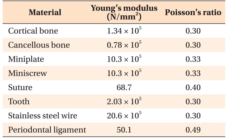
The thickness of the cortical bone was modeled according to a study by Farnsworth et al.20; the thickness of the periodontal ligament was 0.2 mm21; and the width of the maxillofacial sutures was 0.5 mm.22 The mechanical properties of the cortical bone, cancellous bone, tooth, mini-plates, mini-screws, stainless steel (SS) wires, periodontal ligament, and sutures in the 3D finite element model were prepared in accordance with those described in previous investigations (Table 1).517181923 The foramen magnum was fixed and set as the origin point, as presented by Gautam et al.24 The forehead was in contact with a fixed band.
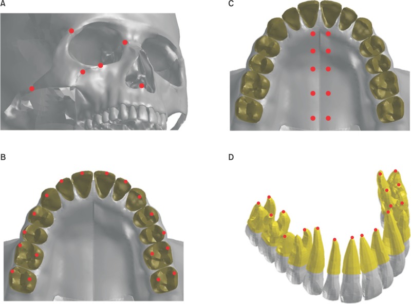
The skeletal and dental landmarks used in this study are depicted in Figure 1. For skeletal landmarks on the maxillofacial complex, the following six variables were used: anterior nasal spine (ANS), orbitale, and the middle points of the frontomaxillary, frontozygomatic, zygomaticomaxillary, and zygomaticotemporal sutures. In addition, five other skeletal variables were used in the paramedian region along the midsagittal suture at the level of the incisive foramen, 1st premolar, 2nd premolar, 1st molar, and distal end of the 2nd molar. For evaluating the dental changes, the following landmarks were employed at the crown level: the middle point of the incisor edge of the incisors, the cusp tips of the canines and 1st and 2nd premolars, and the mesiobuccal and palatal cusp tips of the molars. In addition, the dental landmarks at the root level were as follows: the root tips of the incisors, canines and 2nd premolars, the lingual root tips of the 1st premolars, and the palatal and mesiobuccal root tips of the molars.
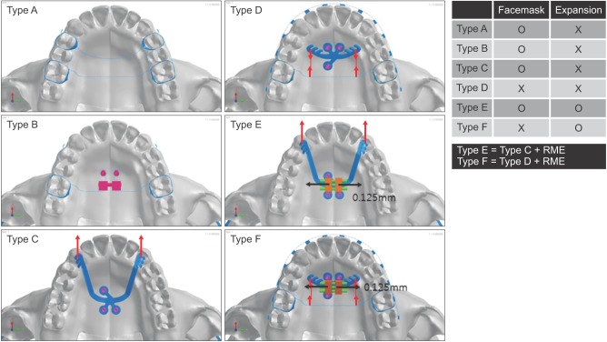
The 3D co-ordinates were defined as the X plane, sagittal plane; Y plane, transverse plane; and Z plane, vertical plane. Positive values indicated forward, outward, and upward displacements on the X, Y, and Z planes, respectively. The 3D finite element models of six appliances were constructed: conventional facemask (Type A), facemask with a dentoskeletal hybrid anchorage appliance (Type B), facemask combined with skeletal anchorage via the palatal plate (Type C), intraoral traction using a Class III palatal plate as an anchorage and a transpalatal arch (TPA) as a handle to move the dentition (Type D), facemask with the palatal plate combined with RME (Type E), and Class III palatal plate intraoral traction with RME (Type F) (Figure 2). These models were integrated to the skull model by using the projection method.24
In Type A, the 1st premolar and the 1st molar were banded and connected with 0.9-mm SS round wire on both the buccal and lingual sides. They were also connected to the contralateral sides through a TPA by using the same size SS wire. A protraction hook was attached to the band of the 1st premolar with its terminal end positioned 2 mm above the gingival crest of the alveolar bone between the canines and 1st premolars.
Type B consisted of the RME appliance, which was connected to the maxillary 1st molar bands by connecting the 0.9-mm SS TPA wires. In addition, two mini-implants (Ortho Easy; Forestadent, Pforzheim, Germany) that were 8 mm in length and 2 mm in diameter, were inserted into the screw holes extending from the RME appliance at 2 mm in the paramedian aspect of the midpalatal suture along the level of the maxillary 2nd premolars in the anteroposterior direction. This hybrid form of the RME appliance, supported by the implant as well as dental units, was subjected to protraction force without expansion. In addition, the hooks for the facemask were attached from the 1st molar band and ended in a compatible position as in Type A.
Type C consisted of the palatal plate with three hooks on each arm (thickness, 0.80 mm; width, 2.0 mm; half side length, 28.0 mm; Jeil Medical Co., Seoul, Korea). The palatal plate was fixed to the palate with three miniscrews (diameter, 2 mm; length, 8 mm; Jeil Medical Co.) placed into the screw tubes (2 mm in diameter) 2 mm lateral from the midpalatal suture. The terminal end of the palatal plate was placed between the canine and 1st premolar at the gingival level.
Type D consisted of a Class III palatal plate with two arms and four hooks on each (thickness, 0.80 mm; width, 2.0 mm; half side length, 15.0 mm; Jeil Medical Co.). Three mini-screws (diameter, 2.2 mm; length, 9 mm) were inserted into the screw holes (diameter, 2.2 mm; two anterior and one posterior) 3 mm away from the midpalatal suture. The terminal end of the plate was positioned at the level of the palatal gingival margin of the first premolar. In addition, 0.022-inch (in) slot brackets (OmniArch; Tomy, Tokyo, Japan) were placed on all teeth and a 0.019 × 0.025-in SS arch wire was engaged. The 1st molars were banded and connected using a SS TPA.
In Types B, C, and D, the miniscrews were rigidly connected to the bone by sharing nodes, because exerting stress around the miniscrews was not the aim of this study. A protraction force of 400g was applied per side at the hooks of Types A, B, and C in a forward and 30° downward vector to the maxillary occlusal plane to minimize the counterclockwise rotation caused by maxillary protraction below the center of resistance.25 In Type D, 300g of force was applied at the hook of the TPA in a forward direction, along the line connecting the hook to the Class III palatal plate notches.
Types E and F were modified versions of Types C and D, respectively, created by adding a miniscrew-assisted RME (MARME) appliance. Moreover, the palatal plate in Types E and F was modified so that, rather than functioning as an intact single piece as in Types C and D, the right and left palatal arms were separated in the middle to become part of each half of the MARME appliance body. This extending form of the palatal arms from the MARME appliance was designed to allow for transverse expansion between the two contralateral sides. In both Types E and F, the expansion screw was activated by one turn (0.25 mm), leaving 0.125 mm of activation per half of the maxilla. Coincidentally, the protraction force was applied using a facemask (Type E) or mesially directed traction to the TPA (Type F) in the same manner as in Types C and D, respectively, considering the magnitude and direction of force as well as its point of application.
Stress distribution and displacement of the landmarks in the maxillofacial bone were analyzed. PAM-MEDYSA V 2011 software (ESI Group) was used for analysis and Visual-Viewer 7.0 (ESI Group) was used for post-processing.
RESULTS
Displacement of landmarks at the maxillofacial sutures
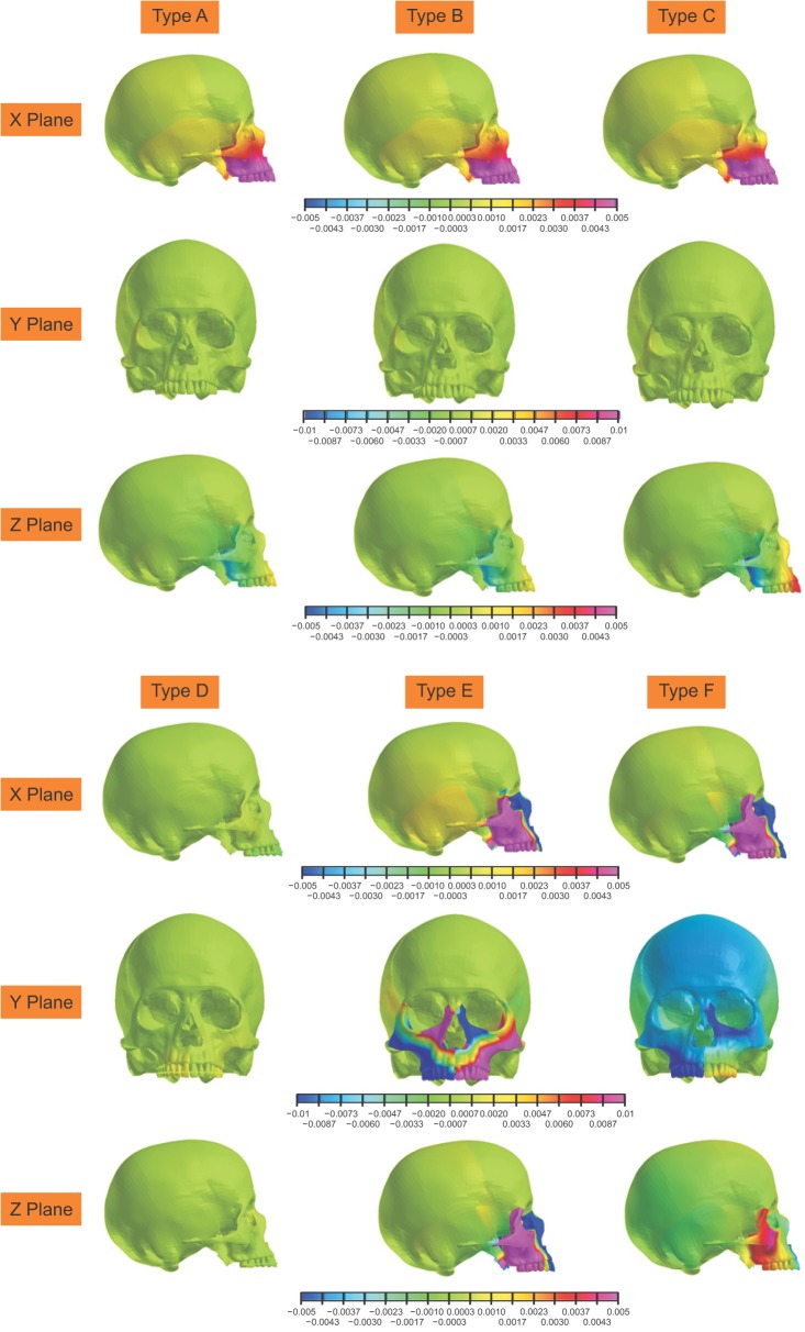
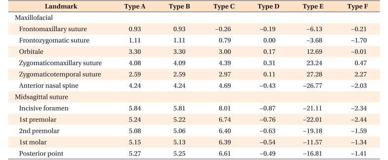
Types A, B, and C showed significant anterior movement in the sagittal plane (Table 2). Types A and B showed similar amount of forward movement (ANS, 4.24 µm), and Type C showed the largest forward movement (ANS, 4.69 µm). Moreover, the relatively inferiorly positioned landmarks, such as the ANS, presented greater amount of sagittal displacement than did the more superiorly positioned landmarks, such as the frontomaxillary and frontozygomatic sutures.
In Types D, E, and F, the ANS showed posterior displacement, while the zygomaticomaxillary and zygomaticotemporal sutures showed anterior displacement. Type E showed the most backward displacement of the anterior maxilla (ANS, 26.77 µm), followed by Type F (Figure 3 and Table 2).
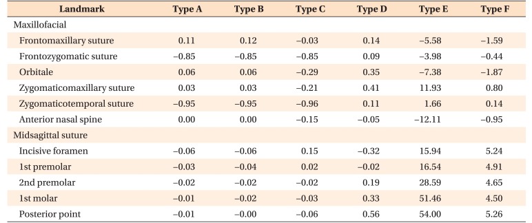
In the transverse plane, Types A and B showed no displacement of the ANS. In Type C all maxillofacial landmarks were medially displaced while, in Type D, all landmarks were laterally displaced except the ANS.
With expansion, Types E and F showed lateral displacement of the zygomaticomaxillary (Type E: 11.93 µm and F: 0.14 µm) and zygomaticotemporal (Type E: 1.66 µm and F: 1.66 µm) sutures, while all other landmarks showed medial displacement (Figure 3 and Table 3).
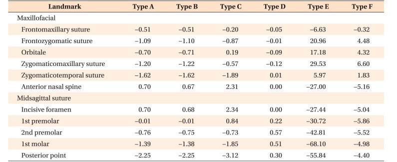
Vertically, in Types A and B, all landmarks were displaced downward except the ANS (0.67 µm; Table 4). In Type C, the ANS was displaced upward more than in the other types (2.31 µm), while the zygomaticotemporal suture showed downward displacement more than in the other types. In Type D the displacement was minimal with no displacement of the ANS. Type E showed significant downward movement of the ANS (−27.00 µm), as well as upward movement of the frontozygomatic and zygomaticomaxillary sutures. Type F showed a similar displacement pattern as Type E, but the amount of displacement was much smaller than that in Type F (Figure 3 and Table 4).
Displacement of landmarks at the midpalatal suture (Tables 2,3,4)
Types A and B showed similar amount of anterior displacement along the suture ranging between 5.84 and 5.81 µm. This was accompanied by the downward displacement of the posterior region and upward displacement of the anterior.
In Type C, the anterior displacement was more pronounced than in the other types, ranging between 6.61 and 8.01 µm. Vertically, the midpalatal suture showed the same pattern of rotation as Types A and B, but with greater magnitude.
In Type D, the midpalatal suture showed backward displacement ranging between −0.87 µm anteriorly and −0.49 µm posteriorly, with upward displacement of all the midpalatal suture landmarks.
In Type E, the midpalatal suture showed backward displacement ranging between −21.11 µm anteriorly and −16.81 µm posteriorly. Transversely, remarkable lateral displacement was observed, increasing from the anterior (15.94 µm) to the posterior (54.00 µm) direction. Vertically, the midpalatal suture showed downward displacement, increasing from the anterior (−27.44 µm) to posterior (−55.84 µm) direction.
Type F showed a similar displacement tendency as Type E, but with much reduced magnitudes. In all three planes of space, the difference between the anterior and posterior regions was narrower in Type F than in Type E.
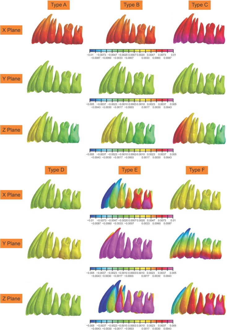
Displacement of teeth (Figure 4)
In the sagittal plane, Types A and B showed anterior displacement of all dentition, which ranged from 4.77 to 6.65 µm. Also, the amount of anterior displacement was most pronounced in Type C (9.04 to 9.84 µm). In contrast, Types D and F showed slight posterior displacement of the incisors (−0.95 and −1.46 µm, respectively). In Type E, the incisors moved posteriorly (−14.18 µm), whereas the molars moved anteriorly (12.02 µm).
Transversely, Types A, B, C, and D displayed little displacement. Type E showed outward displacement, gradually increasing from the anterior (18.6 µm) to posterior (62.8 µm) direction. Type F showed more outward displacement at the crown level (10.4 µm) than at the root level.
Vertically, Types A and B showed superior displacement of the incisors (1.18 µm to 1.48 µm) and inferior displacement of the molars (−1.54 to −1.6 µm). Type C displayed a similar movement but with a greater magnitude of 4.07 mm at the incisors and −1.58 µm at the 2nd molars. Type D showed little movement in the vertical plane. With expansion, Types E and F showed inferior displacement of the incisors (−3.34 to −19.3 µm) and superior displacement of the molars (3.39 to 1.7 µm).
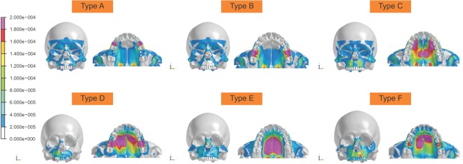
Von Mises stress distribution (Figure 5)
Without expansion, Types A, B, and C showed a concentration of stress on their anchor systems, the pterygoid plates, and zygomatic arches. In Type D, the stress was more localized on its anchor system only.
With expansion, Types E and F displayed a reduced amount of stress on the circummaxillary sutures, whereas more uniform stress distribution was evident surrounding their palatal anchor systems.
DISCUSSION
Owing to the development of various treatment modalities, the use of temporary anchorage devices (TADs) has received increasing attention in maxillary protraction among growing patients with midface deficiency.34 Infrazygomatic miniplates have shown their effectiveness as a skeletal anchor system in the correction of Class III malocclusion, but their placement and removal procedures tend to be more invasive beyond routine clinical orthodontic management, often mandating the involvement of other specialists such as oral surgeons. In contrast, the placement of the palatal plate could be performed at a single site without a flap or incision, and with minimum risk to any vital anatomical structures.1011 This study evaluated the effectiveness of various appliances placed on the palatal area for maxillary protraction through the analysis of initial displacement and stress distribution of the maxillofacial complex during dentoskeletal maxillary protraction.
Our evaluation of various palatal approaches showed that Type C, i.e., the palatal plate, resulted in more anterior displacement than did conventional tooth-borne and hybrid dentoskeletal appliances. This finding is in agreement with that of Kim et al.,13 who reported that the palatal plate resulted in more forward displacement and wider stress distribution than did infrazygomatic miniplates and conventional tooth-borne appliances.
In our study, Types A, B, and C showed both forward movement and counterclockwise rotation of the maxilla. Interestingly, the displacement patterns of Types A and B were similar to each other, but different from that of Type C. In other words, Types A and B showed slight downward movement of the posterior maxilla, whereas Type C displayed a greater magnitude of downward movement of the posterior maxilla coupled with an increased amount of superior movement of the anterior maxilla (Figure 3). It signifies that the counterclockwise rotation of the maxilla tended to be much stronger in Type C than in Types A and B. This is most likely because the point of force application in Types A and B was similar (2 mm apical to the gingival crest of the alveolar bone between the canines and premolar), despite the design of these two anchor systems being distinctly different. Compared to Types A and B, Type C had a more inferior and anterior point of force application, further away from the center of resistance of the anterior maxillary complex. To minimize counterclockwise rotation of the maxilla, changing the position of the hook to a more forward location or directing the force vector more downward may be advantageous.
With intraoral traction, Types D and F demonstrated decreased amount of skeletal effects than did the other models, which employed extraoral approaches. In Types D and F, the maxilla served as an anchorage reinforced by TADs in an attempt to promote anterior movement of dentition, whereas in Types A, B, C, and E the maxilla was directly exposed to an extraoral traction directed anteriorly. This difference in the role of the maxilla explains the different amounts of displacement and stress distribution among the models. In this regard, Types D and F may be better described as maxillary dentitional protraction devices. In fact, to prove their effectiveness as protraction appliances, the dentitional protraction movements of Types D and F should exceed their reactive skeletal movements in a posterior direction simultaneously. Interestingly, the results of this study showed that Types D and F did not display significant dental or skeletal movement in the X plane, except that Type F showed changes most likely caused by expansion, not protraction, module of the appliance. Therefore, the results of this study suggest that the efficacy of Types D and F in the treatment of Class III malocclusion may be questionable.
Between Types C and E, it was Type C, i.e., the palatal plate without expansion, that showed more forward displacement. In agreement, Park et al.16 reported that the bone-borne expander had a negative or no influence on protraction. In a randomized controlled trial, Vaughn et al.26 found no significant difference in treatment effects between protraction with and without palatal expansion. In this study, RME was activated one turn for 0.125 mm of activation per side, with simultaneous application of protraction force. Perhaps, the effects of palatal expansion on maxillary protraction could be caused by factors such as the design and location of the expanders, and their mode of activation. Depending on the position and magnitude of force exerted by the RME appliance within the palatal vault, the forward movement of the maxilla may have been either unaffected or attenuated.
The results of our study are also consistent with those of previous clinical trials on maxillary protraction using different TADs. Recent prospective studies have demonstrated that bone-anchored maxillary protraction (BAMP) with facemask produced significantly larger maxillary advancement than did RME and facemask therapy.2728 Several studies have evaluated the effects of two different protocols of BAMP, comparing the facemasks with the zygomatic buttress miniplates versus the infrazygomatic miniplates and symphyseal miniplates connected with Class III elastics. These studies found that vertical changes and retroclination of the mandibular incisors were better controlled by Class III elastics from the infrazygomatic miniplates in the maxilla to the symphyseal miniplates in the mandible.29 Considering these results, the method of using the palatal plates and symphyseal miniplates with intraoral elastics may be worthwhile to explore as a viable alternative in the future.
In the vertical plane, Types A, B, and C showed counterclockwise rotation of the maxilla. With expansion, however, Types E and F resulted in clockwise rotation of the maxilla. Gautam et al.30 also found that the upward and forward rotational tendency of the maxilla under protraction forces was not observed when maxillary expansion was performed simultaneously.
Between the two bone-borne expanders, the midpalatal suture was opened more uniformly in Type F, but more widely with a posteriorly increasing magnitude in Type E. This is presumably because in Type F, the arch wire was inserted into the brackets and the TPA functioned to retain the form functioning as bolts and nuts. Our results are also consistent with the treatment effects of the bone-born expander in other studies, which showed more expansion in the posterior area than in the anterior area.31 These results may be explained by the specifications and structure of the finite element models, since the load was directly applied to the posterior palate that has thinner cortical bone than does the anterior palate.
With expansion, the stress distribution of the circummaxillary sutures decreased while the amount of maxillary complex displacement increased. In addition, Type E, i.e., facemask with the palatal plate combined with RME, displayed the highest magnitude of stress distribution throughout the palatine bone. In contrast, Type D, i.e., Class III palatal plate with intraoral traction, showed decreased amount of stress distribution in the skull and maxillary complex.
Types C and E with the palatal plates showed minimal stress concentration around the maxillary dentition. This observation suggests that more desirable treatment outcome may be obtained using Types C and E with reduced dental and increased skeletal effects based on the direct application of force to the maxillary base.
In addition, the designs of Types E and F were such that the left half of the maxilla was forced to expand laterally by using only one screw, while the opposite side was anchored by two screws. This non-symmetric shape of the appliances was based on the form of the modified C-palatal plate, which was stabilized by three screw anchors. Although the initial skeletal and dental responses depicted by the finite element model support the effective transverse expansion by both Types E and F, clinical considerations suggest that more symmetric appliance design with four screw anchors, i.e., two on each side, would have been more advantageous to sustain greater amount of stress and to produce more balanced treatment effects.
In this investigation the effects of intraoral and extraoral approaches of the palatal plate were compared, and these have not been previously reported in the literature. Moreover, the effects of RME were presented in conjunction with those of maxillary protraction supported by the palatal plate anchor system. The clinical significance of this study was that the palatal plate may be successfully used for maxillary protraction in facemask therapy.
Our results provide information on the patterns of initial stress distribution and displacement in the maxillary complex during protraction with various palatal appliance designs within the confines of finite element models. Thus, our readers should be aware that the actual clinical situation may present different pictures from what has been discussed here, because muscles, soft tissue, and growth were not considered in our study.
CONCLUSION
On the basis of the finite element model analysis, the palatal plate seemed to provide the most desirable dentoskeletal effects in response to protraction force among the six types of appliances tested in this investigation. Interestingly, the extraoral approach of the palatal plate displayed increased efficiency while the intraoral use of the Class III palatal plate resulted in minimal changes in maxillary protraction. In addition, palatal expansion in conjunction with protraction force demonstrated little added benefit as it presented minimal effect on the forward movement of the maxilla.
 XML Download