

 PDF
PDF ePub
ePub Citation
 Print
Print


INTRODUCTION
Orthodontic miniscrews need to remain stationary in the bone to provide appropriate skeletal anchorage.12 However, miniscrews are often subject to displacement under orthodontic loading, without detectable mobility and loosening.3 Under orthodontic loading, miniscrews remain more stable in D1 (primarily dense cortical bone) and D2 (dense to thick, porous cortical bone at the crest and coarse trabecular bone underneath) bone, because the key determinant for stationary anchorage is the bone density.2 Although the bone density is relatively higher in the adult mandible than in the adult maxilla, the overall failure rate for miniscrews in the mandible is 1.5 times higher (19.3%) than that for miniscrews in the maxilla (12.0%).4
Previous studies have documented that contact between an orthodontic screw and the adjacent tooth root is associated with screw failure.456 Kang et al.5 reported that, over a period of 8 weeks, the failure rate for miniscrews that invaded the tooth roots in the posterior mandible of beagle dogs was 79.2%. Kuroda et al.7 analyzed dental radiographs obtained after miniscrew insertion and classified each screw according to its proximity to the adjacent tooth root: category I, screw absolutely separate from the root; category II, apex of the screw appearing to touch the lamina dura; and category III, body of the screw overlaid on the lamina dura. They found a significantly low success rate for category III miniscrews, particularly in the mandible. However, this finding is controversial.89 Asscherickx et al.6 performed histomorphometric analyses in their study on beagle dogs in order to identify a correlation between the success rate for orthodontic miniscrews and their distance from adjacent tooth roots. However, the authors could not perform statistical analyses because of the limited number of miniscrews remaining as a consequence of a high failure rate. They suggested that the high failure rate was due to the high frequency of root contact, and that the marginal position of miniscrews may be a risk factor for screw failure.
Dogs, particularly beagles, have most commonly been used for investigating miniscrews inserted in interradicular spaces.10 For orthodontic miniscrews placed in the mandible of beagle dogs, approximately 6 weeks were necessary for sufficient cortical bone healing before orthodontic loading.11 Although it has been reported that orthodontic miniscrews achieve primary stability mainly through mechanical retention in the surrounding cortical bone,12 primary stability can also be achieved in trabecular bone.13 Orthodontic miniscrews achieve partial osseointegration from 3 weeks after insertion; this increases the removal difficulty.2 Furthermore, it was reported that there was no significant difference in miniscrew stability between immediate loading with a 250 g load and delayed loading,1415 although some researchers have recommended delayed loading (from 3 weeks to 3 months).1617 Accordingly, we intended to determine how the amount of bone surrounding an orthodontic miniscrew changes as the miniscrew approaches their adjacent tooth root, with mild orthodontic force load.
The aim of the present study was to perform histomorphometric evaluations of the bone surrounding orthodontic miniscrews according to their proximity to the adjacent tooth roots in the posterior mandible of beagle dogs. An additional aim was to perform histomorphometric evaluations of the bone surrounding the miniscrews according to the loading time.
MATERIALS AND METHODS
Experimental animals
Four male beagle dogs aged 12 to 15 months and weighing 10 to 15 kg were used in this study. The dogs were bred by veterinarians at the Avison Biomedical Research Center at Yonsei University, Seoul, Korea. The experimental protocol was approved by Institutional Animal Care and Use Committee of Yonsei University Health System and the approval number was 2016-0264.
Miniscrews
A total of 24 cylinder-type miniscrews (OAS-T1507; Biomaterials Korea Co., Seoul, Korea) with a diameter of 1.45 mm and screw thread length of 7.0 mm were used for this study.
Experimental procedures
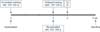
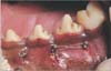
The experimental procedures are depicted in Figure 1. Six miniscrews (three on the left and three on the right) were placed in the buccal interradicular space between the third and fourth premolars (loading group), fourth premolar and first molar (loading group), and second and third premolars (no loading group) in each beagle dog (n = 24). On the basis of previous studies describing the anatomy of the beagle mandible, the miniscrews were placed in regions where the width of the interradicular septum was ≥ 2.2 mm and ≤ 3.2 mm.10 The attached gingiva and alveolar mucosa could not be differentiated at the time of screw insertion (Figure 2).
Before miniscrew insertion, the experimental animal received subcutaneous enrofloxacin (0.5 mg/kg) and intravenous ketorolac (1 mg/kg). The miniscrews were inserted under general anesthesia induced by intravenous atropine (0.05 mg/kg), intravenous ropum (2 mg/kg), and subcutaneous alfaxan (5 mg/kg). Anesthesia was maintained by 2% isoflurane inhalation. All surgical procedures were performed under aseptic conditions. The sites of insertion were assessed using fluoroscopy (C-arm, OEC 9900 Elite; GE OEC Medical Systems Inc., Salt Lake City, UT, USA) before insertion; this aided in visualization of the adjacent tooth roots and the_inserted miniscrews. After confirmation of the roots and interradicular septa on fluoroscopic images, the insertion sites were marked. Then, 2% lidocaine HCl (1:100,000 epinephrine) was infiltrated for local anesthesia at the insertion site, and a 2- to 5-mm vertical incision was placed with a #12 blade. The entire self-drilling insertion procedure was performed under continuous saline irrigation. The insertion angle was perpendicular to the buccal surface, and the insertion orientation was from buccal to lingual. Immediately after miniscrew placement, on the left side in the loading groups, an elastomeric chain (Ormco Co., Orange, CA, USA) was used to load the screws with a 100- to 200-g continuous reciprocal lateral force (immediate loading group, Figure 2). After insertion, each animal received oral amoxicillin clavulanate (14 mg/kg, once a day) and meloxicam (0.2 mg/kg) for 3 days. For 1 week after miniscrew insertion, the dogs received a soft diet. The regions around the miniscrews were irrigated daily with chlorhexidine solution. At 3 weeks, the miniscrews on the right side in the loading groups were loaded with a 100- to 200-g continuous reciprocal lateral force applied using an elastomeric chain (delayed loading group). The force on the left side was reactivated by changing the elastomeric chains. At 4 weeks, the animals received intravenous oxytetracycline hydrochloride (TERA-Inj.; Green Cross Co., Yongin, Korea; 25 mg/kg) for fluorescence microscopy. At 6 weeks, the animals were sacrificed under deep general anesthesia with intravenous KCl. Tissue blocks including the miniscrews were harvested.
Analysis
Miniscrew failure
The harvested tissue blocks were sectioned to prepare histological samples, and each miniscrew was evaluated for mobility on the tissue block. Mobility was defined and graded as follows using a periodontal grading scale for tooth mobility: grade 0, no mobility; grade 1, detectable mobility; grade 2, mobility up to 1 mm; and grade 3, mobility ≥ 1 mm.18
Histomorphometry
The tissue blocks were fixed with 10% formalin solution for 1 month. After fixation, the blocks were serially dehydrated with 70% to 100% concentrated alcohol for 2 weeks. The dehydrated tissue blocks were embedded in polymethyl methacrylate, cut with a diamond saw parallel to the miniscrew axis, and polished to obtain serial sections (approximately 15-µm-thick) using a cutting/grinding system (EXAKT; Exakt Technologies, Inc., Oklahoma City, OK, USA). Nondecalcified ground samples were observed under a fluorescence microscope and subsequently stained with hematoxylin and eosin. Histomorphometric parameters were measured on optical microscopy images. To confirm whether the miniscrews were sectioned parallel to the long axis, the thread lengths were measured again on the tissue sections. Among the many tissue sections, the slice in which the thread length was closest to the original length was selected. Then, the distance from the miniscrew threads to the adjacent root surface was measured on the mesial and distal sides of each miniscrew, and the shorter distance was used to categorize the miniscrews. Bone–implant contact (BIC, %), defined as the percentage of the implant surface in actual contact with bone or osteoid tissue,181920 was measured (at 50× magnification); only the portions of miniscrews embedded in the bone were included in the BIC measurements.
Statistics
SPSS software (version 23; IBM Co., Armonk, NY, USA) was used for all statistical analyses. The Kruskal–Wallis test was used to compare the BIC values among the different root proximity and loading time groups. The Mann–Whitney U-test was used as a post-hoc test. The significance level in all tests was 0.05 (p < 0.05).
RESULTS
Gross mobility
Only one of the 24 miniscrews failed. At 6 weeks after implantation, the failed miniscrew showed grade 3 mobility, whereas the remaining 23 miniscrews did not show mobility (grade 0).
Categorization of the root proximity groups
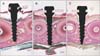
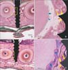
On optical images, the miniscrews were categorized into three groups according to the degree of root proximity, which was based on contact with the bundle bone. The high root proximity group included miniscrews that contacted or invaded the adjacent root. In other words, the shortest distance from the miniscrew threads to the adjacent root surface was a negative value. All miniscrews in this group exhibited more than four threads invading the bundle bone (Figure 3A). In the low root proximity group, the shortest distance from the miniscrew threads to the adjacent root surface was within 0.5 mm. The miniscrews involved the bundle bone or the periodontal ligament but did not contact the adjacent root surface. All miniscrews in this group exhibited less than three threads touching the bundle bone (Figure 3B). In the safe distance group, miniscrews were placed in the interradicular septum and did not contact the bundle bone (Figure 3C).
Histological findings
Histological observations showed that the apex of the failed miniscrew, which was in the immediate loading group, contacted the first molar. No BIC was observed around the failed miniscrew.
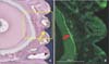
Part of the periodontal ligament space was narrowed in cases where the miniscrew threads touched the bundle bone (Figure 4A). The bundle bone surrounds the periodontal ligament space and is distinguishable from the surrounding trabecular bone by the absence of large blood vessels such as arteries or veins. Fluorescence microscopy showed that tetracycline was deposited on the surface of the alveolar bone facing the periodontal ligament space at 4 weeks after implantation (Figure 4B).
Figure 5 shows that the miniscrew threads that invaded the bundle bone did not exhibit contact with the surrounding bone. Resorption of roots adjacent to these miniscrews was observed at several sites (Figure 5B and 5D).
Histomorphometric analysis
Following repeat measurement of the screw thread length on the tissue sections, the length was found to be within an acceptable range, with a deviation of ± 0.26 mm from the original length. The mean length of the miniscrews on the tissue section was 7.22 mm.
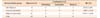
Of the 23 successful miniscrews, 11 were included in the high root proximity group, six in the low root proximity group, and six in the safe distance group. Seven miniscrews in the high root proximity group showed root contact between the fourth premolar and first molar. The mean BIC was 65.72%, 58.07%, and 31.61% in the safe distance, low root proximity, and high root proximity groups, respectively. Thus, BIC was significantly lower in the high root proximity group than in the other two groups (Table 1).
The mean BIC in the unloading, immediate loading, and delayed loading groups was 57.67%, 31.39%, and 47.25%, respectively (Table 2), with no significant differences among groups (p = 0.059; Kruskal–Wallis test).
DISCUSSION
It remains unclear whether the root proximity of orthodontic miniscrews is a major risk factor for miniscrew failure,45678921 although it has been found to be associated with miniscrew failure.24 We attempted to investigate how the root proximity of miniscrews affects the bone surrounding the screws and the adjacent roots. Accordingly, the aim of our study was to perform histomorphometric evaluations of the bone surrounding orthodontic miniscrews according to their proximity with the adjacent tooth roots in the posterior mandible of beagle dogs. We also performed evaluations according to the loading time.
Histological observations revealed that bundle bone invasion by the miniscrews was a factor affecting the bone–implant interface. These results reinforce the postulation that miniscrews belonging to category III, where the entire miniscrew body is overlaid on the lamina dura, show the lowest success rate, particularly in the mandible (35%).7 Kuroda et al.7 categorized the root proximity of miniscrews on the basis of lamina dura involvement. Furthermore, Watanabe et al.21 performed a quantitative analysis using cone beam computed tomography and reported that the mean distance from the failed miniscrew to the adjacent root surface was 0.81 mm at the apex and 0.90 mm at the midsection. Previous studies have reported approximate widths of 0.25 to 0.30 mm and 0.22 to 0.54 mm for the periodontal ligament and lamina dura, respectively, in humans.222324 Therefore, the quantitative results reported by Watanabe et al.21 suggested that the root proximity of miniscrews, which does not necessarily include periodontal ligament or adjacent root surface involvement, could be a risk factor for miniscrew failure.
Histomorphometric analyses performed in the present study revealed that the amount of BIC was significantly low around miniscrews with root contact (high root proximity). The mean BIC for miniscrews contacting adjacent tooth roots was < 35%, while that for miniscrews invading the bundle bone was < 60%. Considering that orthodontic miniscrews exhibited good osseointegration, ranging from 50.1% ± 14.7% at 22 days to 82.5% ± 12.6% at 70 days,25 in the mandible of beagle dogs, the amount of bone surrounding miniscrews with high root proximity may be insufficient for excellent anchorage. Although the bone–implant interface changed from the bundle bone, BIC in the low root proximity group was not different from that in the safe distance group in the present study, possibly because we could not observe the miniscrew corresponding to category III miniscrews (the entire miniscrew body is overlaid on the lamina dura)7 in humans. Furthermore, BIC was not significantly different between the immediate loading and delayed loading groups in the present study. Therefore, we suggest that the loading time is not a critical contributing factor to the hypothesis that the root proximity of orthodontic miniscrews affects the amount of surrounding bone.
Previously, Asscherickx et al.6 tested a hypothesis similar to that examined in the present study using beagle dogs. While their study focused on the miniscrew success rate, we investigated the bone surrounding the miniscrews because we reasoned that stationary miniscrews are fundamentally dependent on support from the trabecular bone and cortical bone. The high failure rate for root-invading miniscrews in beagle dogs could be attributed to several factors, including difficulties in hygiene control and heavy biting forces in dogs and the high frequency of root contact due to narrow interradicular spaces. Therefore, in order to decrease the frequency of root contact, we used miniscrews with a diameter smaller (1.45 mm) than that (1.6 mm or 1.8 mm) of miniscrews used in previous animal studies on root proximity.262728 Moreover, to decrease the failure rate for root-contacting miniscrews, we used the self-drilling insertion method instead of the self-tapping method.262930
To reinforce retrospective radiological studies, histological evaluations of different sections are necessary to obtain precise information.6 To the best of our knowledge, the present study is the first to histologically focus on the bone–implant interface of orthodontic miniscrews according to the root proximity. Interestingly, atrophic changes in the adjacent periodontal ligament were observed when the miniscrew threads touched the bundle bone in the unloading group. Previous researchers suggested that, under orthodontic loading, periodontal ligament compression could indirectly lead to root resorption because of the migration tendency of miniscrews.26 Also, a previous animal study reported that, over a period of 15 weeks and under a 200 to 300 g orthodontic load, root resorption increased from a distance of 0.6 mm between the miniscrew and the root.27 The present study showed resorption of the adjacent tooth root in cases where the miniscrew threads invaded the bundle bone.31
Several limitations of this study should be noted. First, because the sample size was relatively small, and because it was difficult for the operator to intentionally control the distance from the miniscrew to the root, we categorized the root proximity groups using histological sections. As such, we were unable to perform statistical analyses with a high power or examine the association between the distance from the adjacent root and BIC. Second, the loading direction and the cortical bone thickness could have been different, leading to possible biases. In the future, researchers should conduct well-designed studies to investigate the correlation between partial osseointegration and all classes pertaining to the amount of root proximity or the portion of the miniscrew with root proximity. Furthermore, future studies should observe how root proximity-induced damage to adjacent tooth roots changes under different loading conditions for orthodontic miniscrews.
CONCLUSION
Our findings suggest that, regardless of the orthodontic loading time, the stability of an orthodontic miniscrew is decreased if it contacts the bundle bone as well as the adjacent tooth root. In order to maintain a safe distance from the adjacent tooth root, clinicians should consider positioning orthodontic miniscrews without any contact with the bundle bone in the interradicular septum.

 XML Download