This article has been
cited by other articles in ScienceCentral.
Abstract
Generally dentures are manufactured by conventional method, however the frequency of fabricating denture using digital method is increasing due to the recent development of digital technology in dentistry. The digital method of manufacturing denture is classified into two systems; 3D scan of the impression to arrange the artificial teeth on the CAD (Computer-aided design) and 3D printing to produce the resin-based complete denture, or 3D scan of the model to design of the framework using CAD, resin pattern formation by 3D printing and casting of metal framework of complete denture or removable partial denture. In this case report, electronic surveying and design the metal framework of the dentures were performed using CAD program, and plastic resin patterns fabricated by 3D printing were casted for upper full denture and lower removable partial denture. During follow-up periods, dentures using digital method have provided satisfactory results esthetically and functionally.
Keywords: Computer-aided design, Electronic surveying, 3D printing
Figures and Tables
Fig. 1
Initial intraoral view. (A) Occlusal view of maxilla, (B) Lateral view (right side), (C) Frontal view, (D) Lateral view (left side), (E) Occlusal view of mandible.

Fig. 2
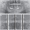
Radiograph at the patient's first visit. (A) Panoramic view, (B) Temporomandibular joint (TMJ) series.

Fig. 3
Electronic surveying on diagnostic model of mandible shows degree of undercut by different color. (A) Occlusal view, (B) Lateral view (right side), (C) Lateral view (left side).

Fig. 4
Metal framework of maxillary complete denture designed by CAD, and resin pattern was fabricated by 3D printer. (A) Master model of maxilla, (B) Block out of 3D scan model, (C) Mesh coverage setting, (D) Design of metal framework, (E), (F) Resin pattern fabricated by 3D printer, (G) Resin pattern for casting, (H) Wax-rim with metal framework.

Fig. 5
Jaw relation record using Gothic arch tracer. (A) Wax-rim with Gothic arch tracing, (B) Bite registration.

Fig. 6
Electronic surveying on mandibular surveyed crowns shows ideal undercut degrees of retentive arms. (A) Occlusal view, (B) Lateral view (right side), (C) Lateral view (left side).

Fig. 7
Metal framework of mandibular removable partial denture designed by CAD, and resin pattern was fabricated by 3D printing. (A) Master model of mandible, (B) 3D scan of model, block out, (C) Design of major connector, (D) Design of finishing line and sprue, (E) Resin pattern fabricated by 3D printer, (F) Resin pattern for casting, (G), (H) Metal framework, (I) Wax-rim with metal framework.

Fig. 8
Intraoral view of definitive prosthese. (A) Occlusal view of maxilla, (B) Lateral view (right side), (C) Frontal view, (D) Lateral view (left side), (E) Occlusal view of mandible.

Fig. 9
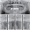
Radiograph of patient after delivery of final dentures. (A) Panoramic view, (B) Temporomandibular joint (TMJ) series.


 PDF
PDF ePub
ePub Citation
 Print
Print


 XML Download