Journal List > Prog Med Phys > v.28(4) > 1098580

Oh, Shin, Kim, Kwon, Lee, Choi, Ahn, Park, and Kim: Proposal on Guideline for Quality Assurance of Radiation Treatment Planning System

Abstract

We develop guidelines for the quality assurance of radiation treatment planning systems (TPS) by comparing and reviewing recommendations from major countries and organizations, as well as by analyzing the AAPM, ESTRO, and IAEA TPS quality assurance guidelines. We establish quality assurance items for acceptance testing, commissioning, periodic testing, system management, and security, and propose methods to perform each item within acceptable standards. Acceptance includes tests of hardware and network environments, data transmission, software, and benchmarking as specified by the system supplier, and apply the IAEA classification criteria. Commissioning includes dosimetric and non-dosimetric items for assessing TPS performance by applying the AAPM classification criteria and the latest technical items from the IAEA. Periodic quality assurance tests include daily, weekly, monthly, yearly, and occasional items by applying the AAPM classification criteria. System management and security items include the state and network connectivity of TPS, periodic data backup, and data access security. The guidelines for TPS quality assurance proposed in this study will help to improve the safety and quality of radiotherapy by preventing incidents related to radiotherapy.

REFERENCES

1.Whosaeng: Increased radiation therapy in cancer patients. http://m.whosaeng.com/a.html?uid=94023.
2.KEIT. 2017. PD Issue report. Technology trend and industry status of radiation therapy equipment. Korea Evaluation Institute of Industrial Technology.
3.WHO. 2008. Radiotherapy risk profile. World Health.
4.RPOP. Short case histories of major accidental exposure events in radiotherapy. https://rpop.iaea.org/RPOP/RPoP/Content/InformationFor/HealthProfessionals/2_Radiotherapy/AccidentPrevention.htm.
5.IAEA. Technical Reports Series no. 430. Commissioning and quality assurance of computerized planning systems for radiation treatment of cancer. International Atomic Energy Agency, Vienna. 2004. 430.
6.ESTRO. 2004. Booklet no. 7. Quality assurance of treatment planning systems. Practical examples for non-IMRT photon beams. European Society for Radiotherapy & Oncology.
7.AAPM. 1998. Radiation Therapy Committee Task Group 53. Quality assurance for clinical radiotherapy treatment planning. American Association of Physicists in Medicine.
8.NSSC. 2015. Notification no. 2015-005. Technological standards for radiation safety of medical field. Nuclear Safety and Security Commission.
9.KSMP. AAPM Task Group 142 report. Quality assurance of medical accelerators. Korean Society of Medical Physics. 2016. 142.
10.Choi S.., Park D.., Kim K., et al. Suggestion for Comprehensive Quality Assurance of Medical Linear Accelerator in Korea. Prog. Med. Phys. 2015. 26(4):294–303.
crossref
11.Venselaar J.., Welleweerd H.., Mijnheer B.Tolerances for the accuracy of photon beam dose calculations of treatment planning systems. Radiother. Oncol. 2001. 60(2):191–201.
crossref

Fig. 1
Location of dose calculation verification (solid line: measured profile, dot line: calculated profile).
pmp-28-197f1.tif
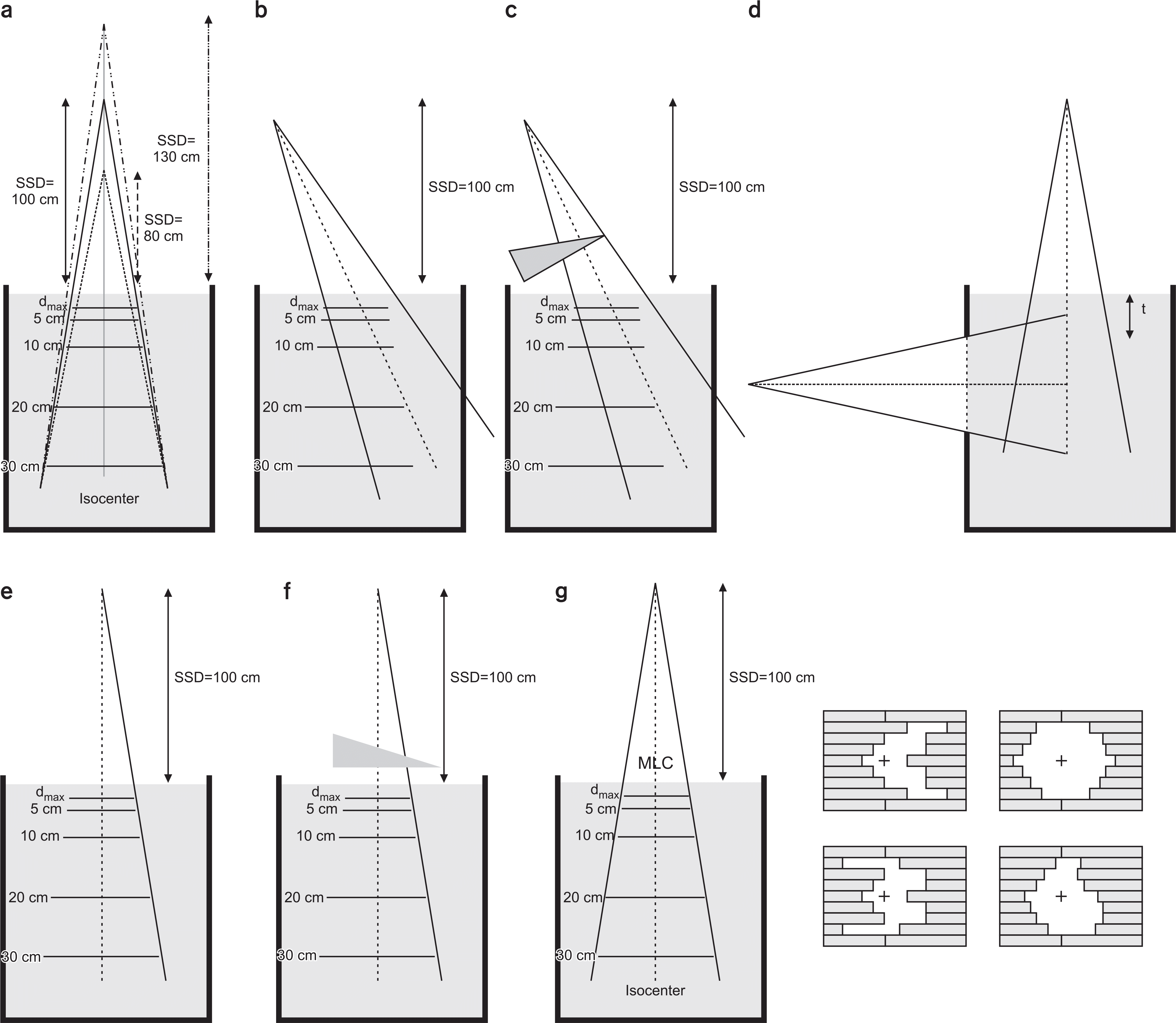
Fig. 2
Verification in (a) SSD variation, (b) open oblique incidence field, (c) wedged-oblique incidence field, (d) missing tissue, (e) open off-axis field, (f) wedged off-axis field, (g) MLC-shaped field.
pmp-28-197f2.tif
Table 1.
Status of acceptance test.
Items AAPM ESTRO IAEA
Hardware Check CPU, monitor, printer, and all peripheral instruments (Not described) Check CPU and memory, disk operation, input/output devices
Network environment (Not described) Network connection Network connection
Data transmission (Not described) Data transmission Data transmission
Software According to specification, mark as ‘exists/does not exist’ Basic patient registration Verification of system functions
    System function check Check calculation functions
      Check utilities
Benchmark test Measurement of accuracy of the dose calculation algorith calculation times under very specific circumstances with specific beam data Basic treatment description Measurement of data for the photon beams of two machines (4 MV and 18 MV linear accelerators) and the results of a series of tests
    Verification of dose distribution MLC field Tests under standard fields
Table 2.
Status of non-dosimetric commissioning.
Items AAPM ESTRO IAEA
Check system (Not described) (Not described) Installation of system hardware
installation     Software selection
      Detailed parameter selection
Patient image data Patient positioning and Image registration Collection of patient data
  immobilization Input of outline data Input and transmission of anatomical data
  Image acquisition    
Outline creation Anatomical description Definition of anatomical structure Creation of the anatomical model
    Outline modification  
    Construction of volumes  
Beam data checks Beam arrangements and Beam geometry Beam parameters
  definition Beam display functions (BEV, beam Beam geometry
  Machine description, limits and location/shape, Block location in Field definition
  readouts BEV, MLC field, Bolus location, Wedges, Beam modifiers
  Geometric accuracy etc.) Normalizations
  Field shape design   Plan output check
  Wedge, compensator   Parameter checks and documentation
  Methodology, algorithms   SAD, SSD setup
  Density corrections, etc.   BEV, field check
      Portal image indicator
Table 3.
Status of dosimetric commissioning.
Items AAPM ESTRO IAEA
Beam data input Measurement of beam dataset Data input Transfer of measured data from water
  Transfer of measured data from Documentation phantom
  water phantom   Algorithm input data
  Manual data entry    
  Verification of input data    
Dose calculation Square and rectangular field Open field and rectangular field Square and rectangular field
  Asymmetric fields Blocked fields Asymmetric fields
  Blocked fields MLC-shaped fields Wedged field
  MLC-shaped field Wedged field SSD variations
  Wedged field Off-axis field Oblique incidence
  External surface variations SSD variations Complicated surface formation
  SSD variations Inhomogeneity Build-up region
  Inhomogeneity, etc. Missing tissue, etc. Density correction
      Inhomogeneity correction
      Compensator, etc.
Examination of 1-D comparisons 2-D and 3-D dose distribution Beam dependence verification
dose calculations Difference between FDD DVH Algorithms and clinical examination
  (fractional depth dose) and TPR   1-D comparison: Depth dose differences
  2-D isodose curve   according to field
  Color wash dose indicator   2-D comparison: isodose curve
  Dose difference indicator   3-D comparison: Comparison of 3-D dose
  DVH analysis   distribution and DVH
  Distance maps    
MU calculation MU calculation MU calculation MU calculation
  MU calculation QA   Process verification
  Process Verification    
Table 4.
Status of periodic quality assurance testing.
Items AAPM ESTRO IAEA
Daily Error and change log (Refer to items for acceptance test) (Not described)
Weekly Computer files   (Not described)
  Review clinical planning    
Monthly CT data input   CPU
  Problem review   Plan details
  Review of RTP system    
Yearly Dose calculation   MUs/time
  Data and I/O devices, critical software tools    
Variable Beam parameterization   Backup recovery
      CT (or other) scan transfer, geometry
      and density check
      Patient anatomy
      MUs/time
Table 5.
Items for acceptance test.
Items Test
Hardware Check whether computer peripheral
  devices operate according to
  specifications
Network environment Check all network connections
  transmitting data in the RTPS and
  the network
Data transmission Check CT and MRI image data,
  treatment plan data transmitted by
  the RTPS, MLC data transmitted
  by the MLC control system, DRR
  data, and data transmitted by
  the compensator design device,
  simulation, and the radiation
  oncology management systems
Software CT input and anatomical
  description, beam data input, dose
  calculations, dose indicators, dose
  volume histograms, document
  output accuracy checks
Benchmark test Check calculation function using
  standard beam data
Table 6.
Items for non-dosimetric commissioning.
Items Test
System installation Hardware and software checks
checks and user definition System limits checks Patient data checks
  Data conversion of RTPS
  Indicators and output devices installation
  checks
  Treatment plan protocol checks
  Conversion of CT number to electron density
  Database checks
Patient anatomical CT image acquisition
description, CT image indicator related tools
transmission, and registration Patient anatomical data formation from other non-CT image modalities and
  manual operations
  Patient database
Structure outline Manual outline formation using CT images
creation Automatic outline formation using CT
  images
  3-D structure formation
  Outline formation using interpolation
  Automatic margin function
  Set-up of relative electron density
  Bolus formation
  Points and line marker definition
Beam data System parameter checks
  System parameter limits
  Collimator and jaw setup
  Shielding block definition and formation
  MLC
  Automatic field formation
  Beam installation checks
  Gantry and collimator, treatment table angle
  Wedge
  Beam
  DRR
Table 7.
Items for dosimetric commissioning.
Items Test
Verification of Comparison of measured and calculated
beam modeling beam data
Verification under Relative dose distribution and absolute
simple conditions dose verification
Verification in Variation in SSD
clinical conditions Open oblique incidence field
  Wedged oblique incidence field
  Missing tissue
  Open off-axis field
  Wedged off-axis field
  Irregular field
  Build-up region
  Inhomogeneity correction (Rectangular
  inhomogeneous model phantom or
  human body phantom)
Table 8.
Tolerance of assessing dose for external radiation treatment.
Dose evaluation region (1) Homogeneous, open field, symmetry beam (2) Simple inhomogeneous wedge, MLC-shaped field, asymmetry beam (3) Beam used by the combination of more than 2 types
δ1 2% 3% 4%
δ2 2 mm, 10% 3 mm, 15% 3 mm, 15%
δ3 3% 3% 3%
δ4 3% (30%) 3% (40%) 3% (50%)
δ(RW50) 2 mm, 1% 3 mm, 1% 3 mm, 1%
δ50-90 2 mm 3 mm 3 mm
Table 9.
Items for periodic quality assurance test
Items Test
Daily Review error log
  Review change log
Weekly Verify computer files
  Verify clinical plan
Monthly Verify stability about CT data and CT value and
  relative electron density
  Review problems of RTPS and prioritize resolution
  of problems
  Review configuration and state of RTPS
Yearly Check concordance between measured and
  calculated dose
  Review accuracy of data and operation of I/O devices
  Review important software
Variable Check beam parameter and restart
  Check software including OS and restart
TOOLS
Similar articles