Abstract
Radiotherapy patients should maintain their treatment position as patient setup is very important for accurate treatment. In this study, we evaluated patient setup error quantitatively according to Cone-Beam Computed Tomography (CBCT) Gamma Density Analysis using Mobius CBCT. The adjusted setup error to the QUASAR™ phantom was moved artificially in the superior and lateral direction, and then we acquired the CBCT image according to the phantom setup error. To analyze the treatment setup error quantitatively, we compared values suggested in the CBCT system with the Mobius CBCT. This allowed us to evaluate the setup error using CBCT Gamma Density Analysis by comparing the planning CT with the CBCT. In addition, we acquired the 3D-gamma density passing rate according to the gamma density criteria and phantom setup error. When the movement was adjusted to only the phantom body or 3 cm diameter target inserted in the phantom, the CBCT system had a difference of approximately 1 mm, while Mobius CBCT had a difference of under 0.5 mm compared to the real setup error. When the phantom body and target moved 20 mm in the Mobius CBCT, there are 17.9 mm and 13.5 mm differences in the lateral and superior directions, respectively. The CBCT gamma density passing rate was reduced according to the increase in setup error, and the gamma density criteria of 0.1 g/cc/3 mm has 10% lower passing rate than the other density criteria. Mobius CBCT had a 2 mm setup error compared with the actual setup error. However, the difference was greater than 10 mm when the phantom body moved 20 mm with the target. Therefore, we should pay close attention when the patient's anatomy changes.
Go to : 
REFERENCES
1.Kim J., Fessler JA., Lam KL., Balter JM., Ten Haken RK. A feasibility study of mutual information based setup error estimation for radiotherapy. Med Phys. 2001. 28:2507–17.

2.Faiz MK. The physics of radiation therapy. 2nd ed.Baltimore: Williams & Wilkins;1992. p. 307–11.
3.Kang SM. Evaluation of setup error Correction for patients using on board imager in image guided radiation therapy. J Korean Soc Rad Ther. 2008. 20(2):69–81.
4.Peng JL., Kahler D., Li JG., Samant S., Yan G., Amdur R., Liu C. Characterization of a real-time surface image-guided stereotactic positioning system. Med Phys. 2010. 37(10):5421–33.

5.Brahme A., Nyman P., Skatt B. 4D laser camera for accurate patient positioning, collision avoidance, image fusion and adaptive approaches during diagnostic and therapeutic procedures. Med Phys. 2008. 35(5):1670–81.

6.Schoffel PJ., Harms W., Sroka-Perez G., Schlegel W., Karger CP. Accuracy of a commercial optical 3D surface imaging system for realignment of patients for radiotherapy of the thorax. Phys Med Biol. 2007. 52(13):3949–63.
7.Bert C., Metheany KG., Doppke KP., Taghian AG., Powell SN., Chen GT. Clinical experience with a 3D surface patient setup system for alignment of partial-breast irradiation patients. Int J Radiat Oncol Biol Phys. 2006. 64(4):1265–74.

8.Krengli M., Gaiano S., Mones E., Ballare A., Beldi D., Bolchini C., Loi G. Reproducibility of patient setup by surface image registration system in conformal radiotherapy of prostate cancer. Radiat Oncol. 2009. 4:9.

9.Bert C., Metheany KG., Doppke K., Chen GT. A phantom evaluation of a stereo-vision surface imaging system for radiotherapy patient setup. Med Phys. 2005. 32(9):2753–62.

10.Ploeger LS., Frenay M., Betgen A., de Bois JA., Gilhuijs KG., van Herk M. Application of video imaging for improvement of patient set-up. Radiother Oncol. 2003. 68(3):277–84.

11.Yamashita H., Haga A., Hayakawa Y., Okuma K., Yoda K., Okano Y., Tanaka K., Imae T., Ohtomo K., Nakagawa K. Patient setup error and day-to-day esophageal motion error analyzed by cone-beam computed tomography in radiation therapy. Acta Oncol. 2010. 49(4):485–90.

12.Nathan Childress. Introducing the Mobius3D CBCT Module. [Internet] ASTRO. 2015. [cited 2015 Nov 12]. Available from:. https://vimeo.com/145572195.
13.Low DA., Harms WB., Mutic S., Purdy JA. A technique for the quantitative evaluation of dose distributions. Med Phys. 1998. 25(5):656–61.

14.Hurkmans CW., Remeijer P., Lebesque JV., Mijnheer BJ. Setup verification using portal imaging; review of current clinical practice. Radiother Oncol. 2001. 58(2):105–20.

15.Mechalakos JG., Hunt MA., Lee NY., Hong LX., Ling CC., Amols HI. Using an onboard kilovoltage imager to measure setup deviation in intensity-modulated radiation therapy for head-and-neck patients. J Appl Clin Med Phys. 2007. 8(4):): 2439.

16.Mobius3D User Guide v. 2.0.1 rev 1.0. Mobius Medical Systems. 2016. 51.
Go to : 
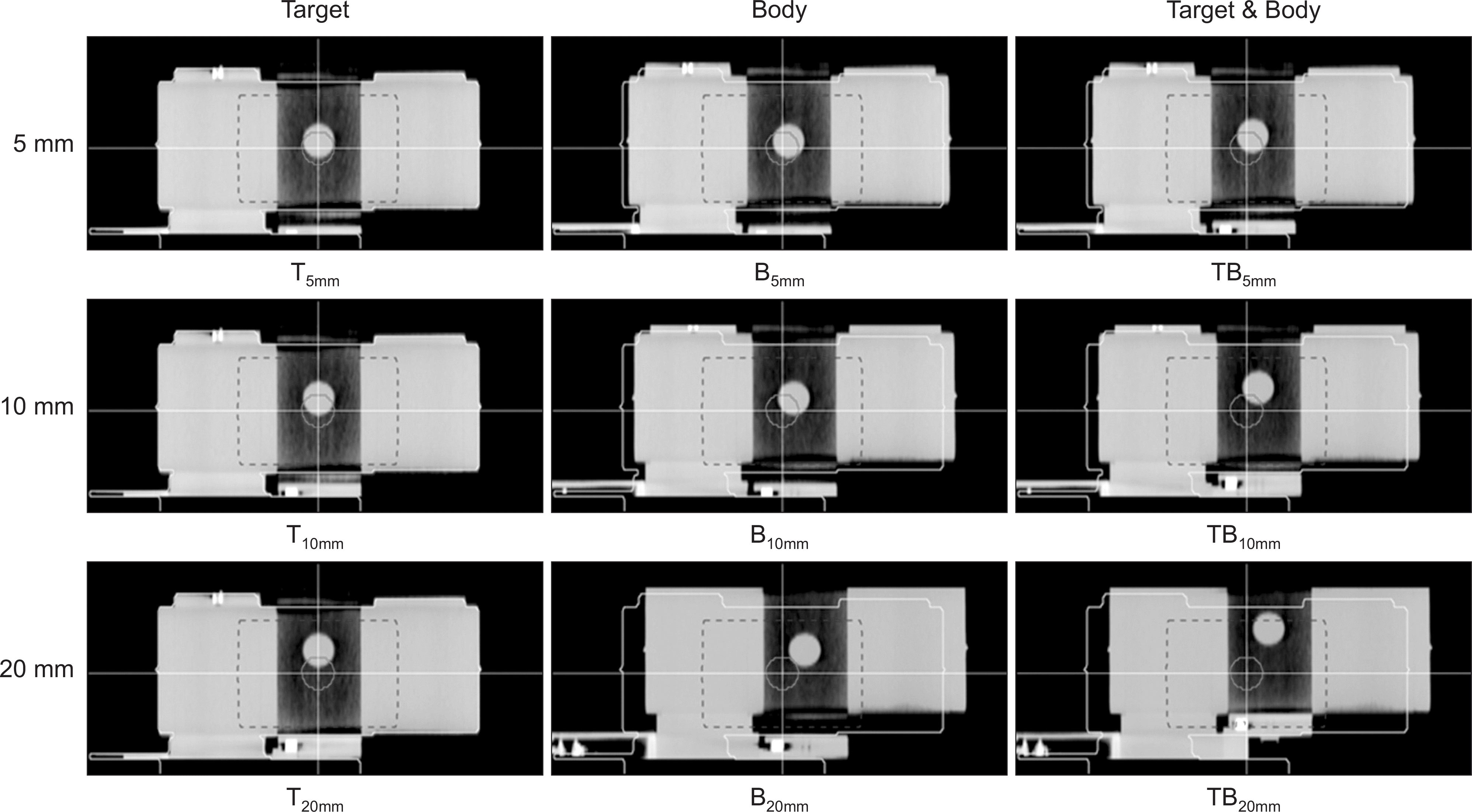
 | Fig. 1The CBCT images according to target and phantom movement. Red solid line and blue dashed line indicate the target ROI and CBCT gamma ROI, respectively. |
 | Fig. 2Plot (a)-(c) illustrate for CBCT gamma density passing rate about Target, Body and Target & Body movement according to DD and plot (d)-(f) is CBCT gamma density passing rate according to DTA. |
Table 1.
Additional position shift suggested in CBCT system and Mobius CBCT.
Table 2.
Additional position shift for Target & Body movement 20 mm according to Gamma Density Analysis criteria and DTA suggested in Mobius CBCT.
| Density (g/cc) | DTA (mm) | Mobius CBCT | |
|---|---|---|---|
| Left | Inferior | ||
| 0.1 | 1 | 0.00 | 0.00 |
| 2 | 0.00 | 0.00 | |
| 3 | 0.00 | 0.00 | |
| 0.2 | 1 | 3.00 | 8.20 |
| 2 | 3.00 | 8.20 | |
| 3 | 3.00 | 8.20 | |
| 0.3 | 1 | 3.00 | 8.20 |
| 2 | 3.00 | 8.20 | |
| 3 | 3.00 | 8.20 | |
Table 3.
The CBCT gamma density passing rate about Target (T), Body (B) and Target & Body (TB) movement according to DTA and DD.


 PDF
PDF ePub
ePub Citation
 Print
Print


 XML Download