Abstract
In this study, we aim to design the architecture of the kV imaging system for tumor tracking in the dual-head gantry system and analyze its accuracy by simulations. We established mathematical formulas and algorithms to track the tumor position with the two-pair kV imaging systems when they are in the non-orthogonal positions. The algorithms have been designed in the homogeneous coordinate framework and the position of the source and the detector coordinates are used to estimate the tumor position. 4D XCAT (4D extended cardiac-torso) software was used in the simulation to identify the influence of the angle between the two-pair kV imaging systems and the resolution of the detectors to the accuracy in the position estimation. A metal marker fiducial has been inserted in a numerical human phantom of XCAT and the kV projections were acquired at various angles and resolutions using CT projection software of the XCAT. As a result, a positional accuracy of less than about 1mm was achieved when the resolution of the detector is higher than 1.5 mm/pixel and the angle between the kV imaging systems is approximately between 90o and 50o. When the resolution is lower than 1.5 mm/pixel, the positional errors were higher than 1mm and the error fluctuation by the angles was greater. The resolution of the detector was critical in the positional accuracy for the tumor tracking and determines the range for the acceptable angle range between the kV imaging systems. Also, we found that the positional accuracy analysis method using XCAT developed in this study is highly useful and will be a invaluable tool for further refined design of the kV imaging systems for tumor tracking systems.
References
1. Lin T, Cervino LI, Tang X, Vasconcelos N, Jiang SB. Fluoroscopic tumor tracking for imageguided lung cancer radiotherapy. Physics in Medicine and Biology. 54(4):981–992. 2009.

2. Shirato H, Shimizu S, Kitamura K, et al. Four-dimensional treatment planning and fluoroscopic real-time tumor tracking radiotherapy for moving tumor. International Journal of Radiation Oncology Biology Physics. 48(2):435–442. 2000.

3. Berbeco RI, Jiang SB, Sharp GC, et al. Integrated radiotherapy imaging system (IRIS): design considerations of tumour tracking with linac gantry-mounted diagnostic x-ray systems with flat-panel detectors. Physics in Medicine and Biology. 49(2):243–255. 2004.

4. Kamino Y, Takayama K, Kokubo M, et al. Development of a four-dimensional imageguided radiotherapy system with a gimbaled X-ray head. International Journal of Radiation Oncology Biology Physics. 66(1):271–278. 2006.

5. Wiersma RD, Mao WH, Xing L. Combined kV and MV imaging for real-time tracking of implanted fiducial markers. Medical Physics. 35(4):1191–1198. 2008.
6. Poels K, Depuydt T, Verellen D, et al. A complementary dual-modality verification for tumor tracking on a gimbaled linac system. Radiotherapy and Oncology. 109(3):469–474. 2013.

7. Jong Seo Chai: Radiation therapy device of dual head type. No. 10–1465650 (. 2013.
8. Segars WP, Mahesh M, Beck TJ, Frey EC, Tsui BM.: Realistic CT simulation using the 4D XCAT phantom. Medical Physics. 35(8):3800–8. 2008.
9. Segars WP, Jason B, Jack F, Sylvia H, et al. Population of anatomically variable 4D XCAT adult phantoms for imaging research and optimization. Medical Physics. 40(4):043701. 2013.

10. Jules B, Jon R. Homogeneous Coordinates. The Visual Computer: International Journal of Computer Graphics. 11(1):15–26. 1994.
Fig. 1.
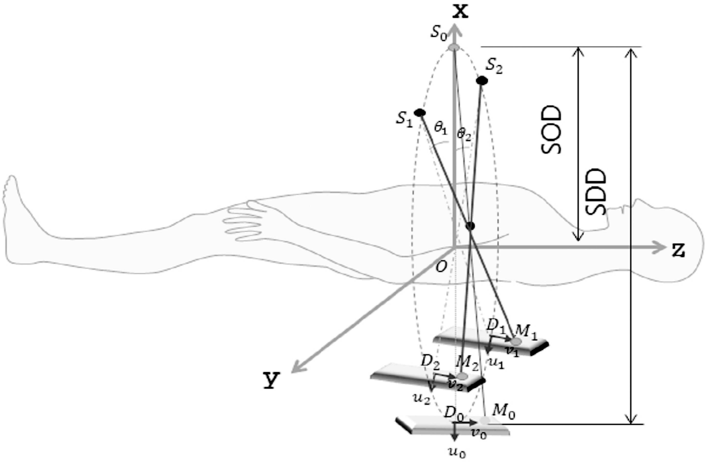
A schematic of the dual-head gantry radiation therapy system. In this system, the dual meta-voltage (MV) accelerators are mounted on the gantry for therapeutic purpose and the kilo-voltage (kV) imaging systems are used for tumor tracking. The motion range of the kV imaging system is limited in the dual-head gantry design.
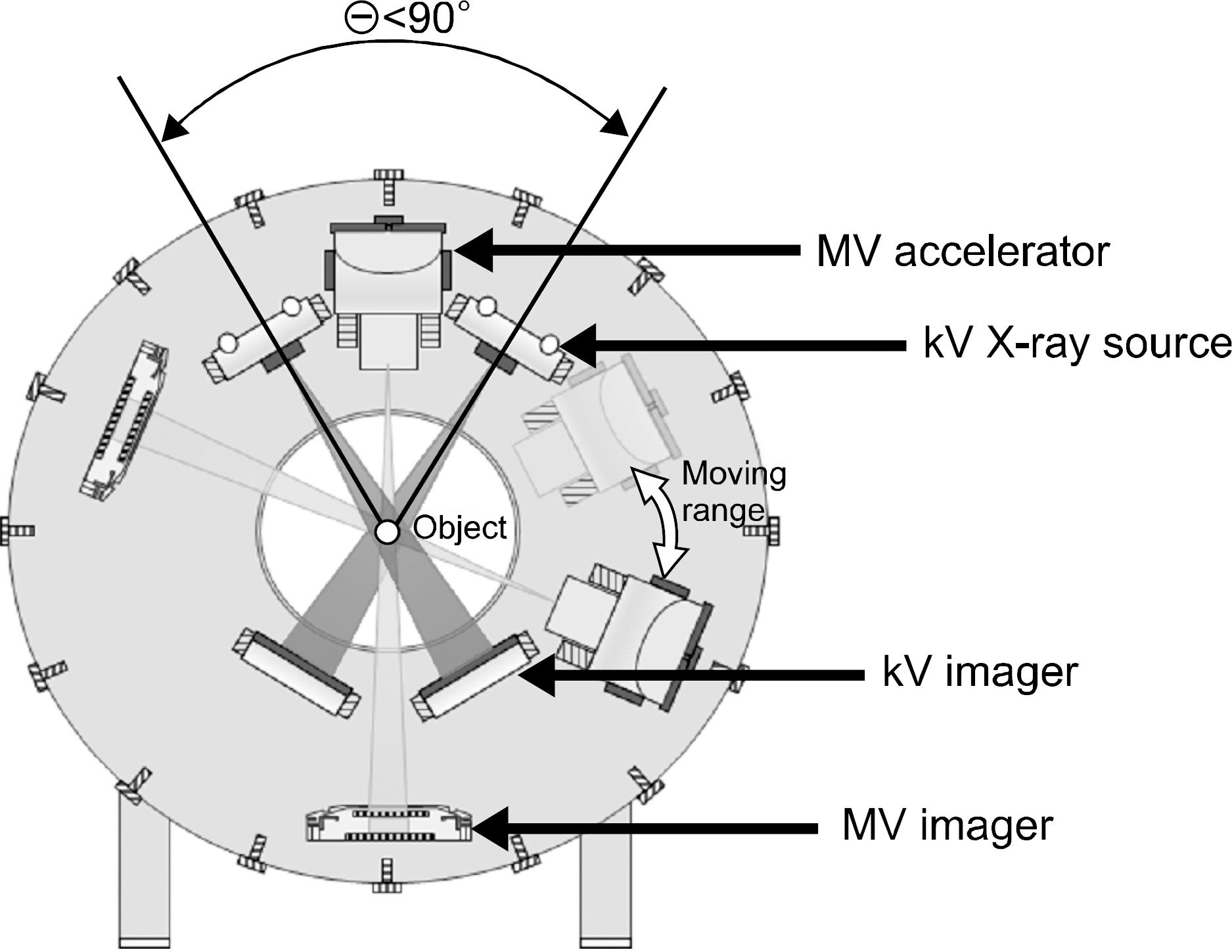
Fig. 4.
Projection images of the human phantom using XCAT. The projections shown here are at each 10o interval for each kV imaging system.
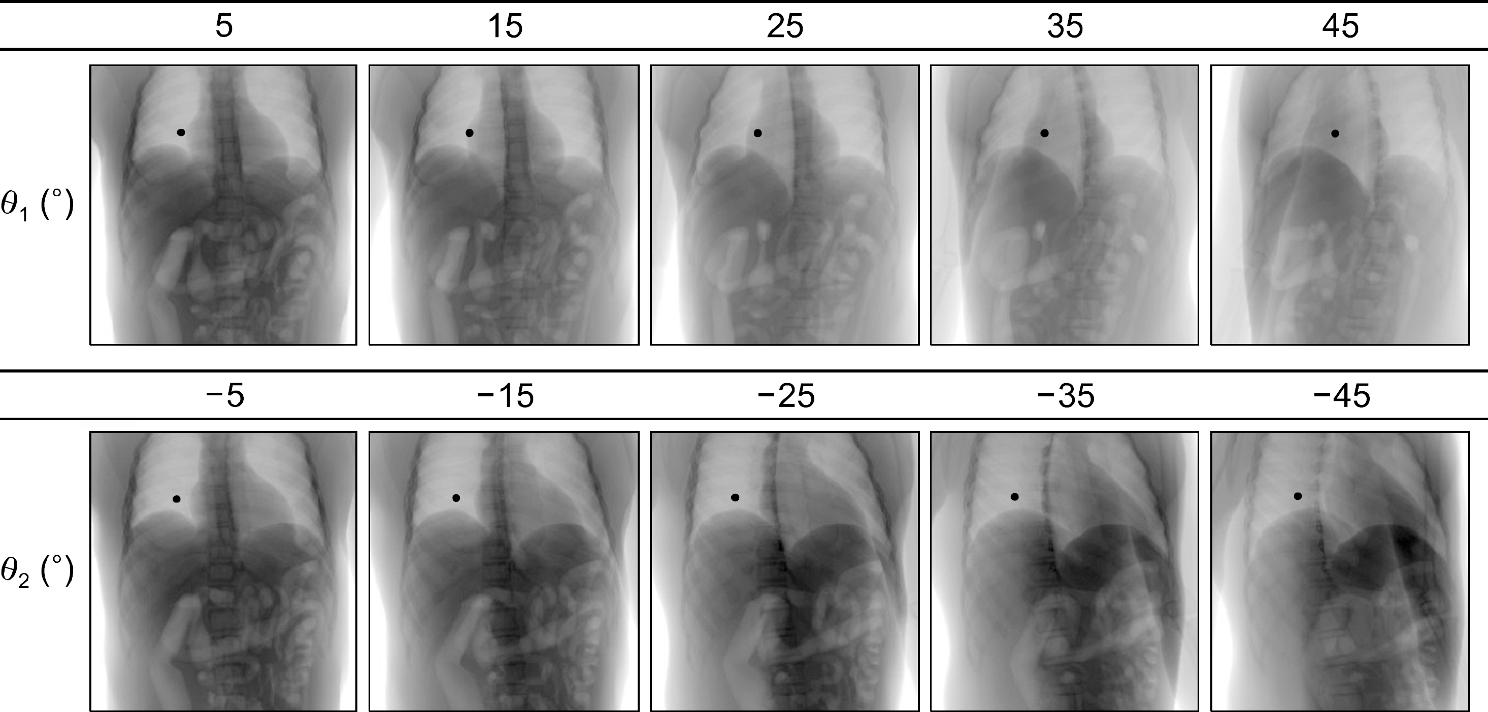
Fig. 5.
Three-dimensional distance errors of the metal marker fiducials along the x, y, z axis for the corresponding angular intervals between two kV imaging systems. (a) Estimation errors for the markers on the x-axis, (b), y-axis, and (c) z-axis.
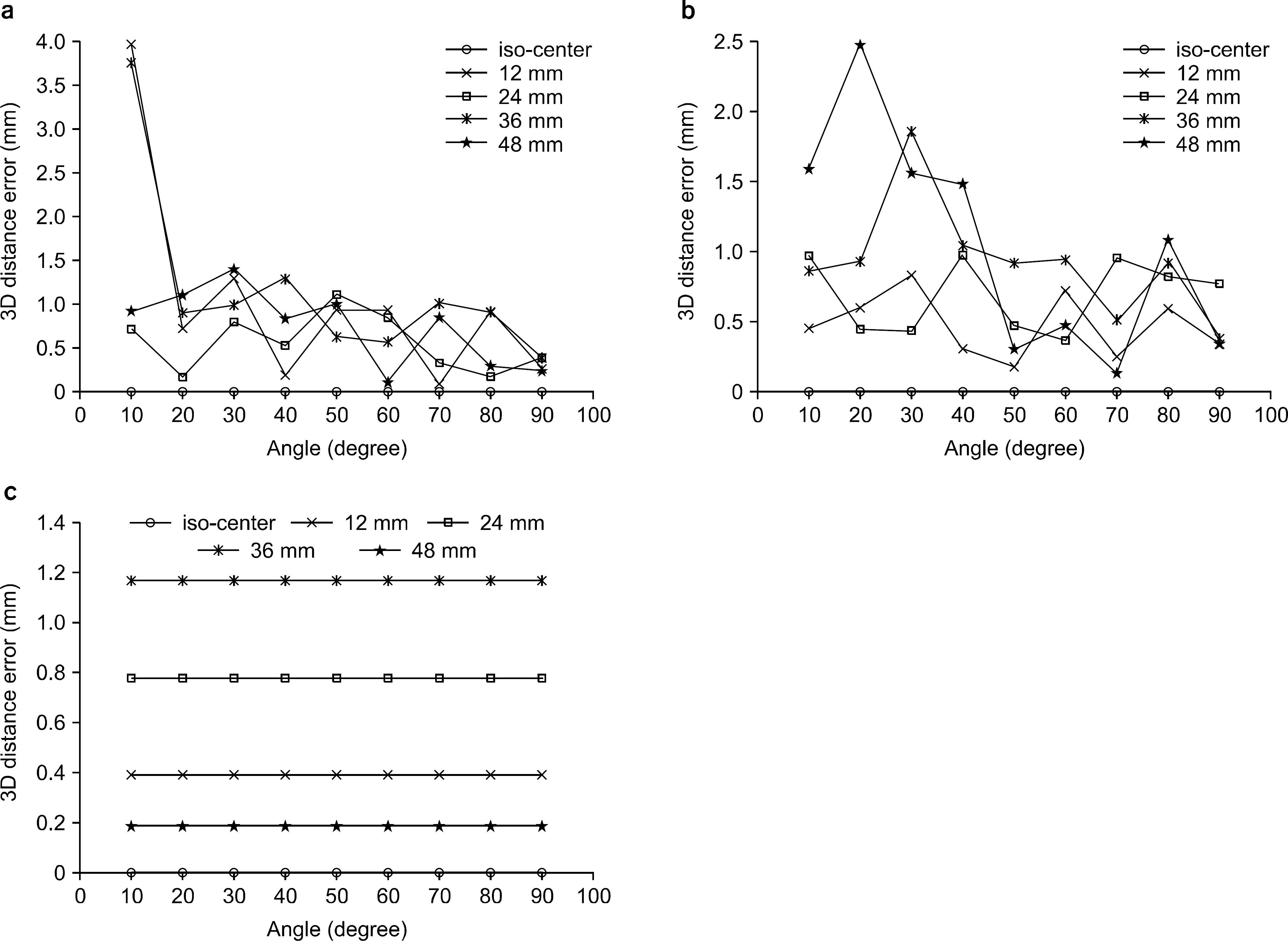
Fig. 6.
The metal fiducial marker at (−31.25, −62.5, 93.75) in the lung and its positional estimation in each x, y, z direction for the given angular intervals between the two kV imaging system.
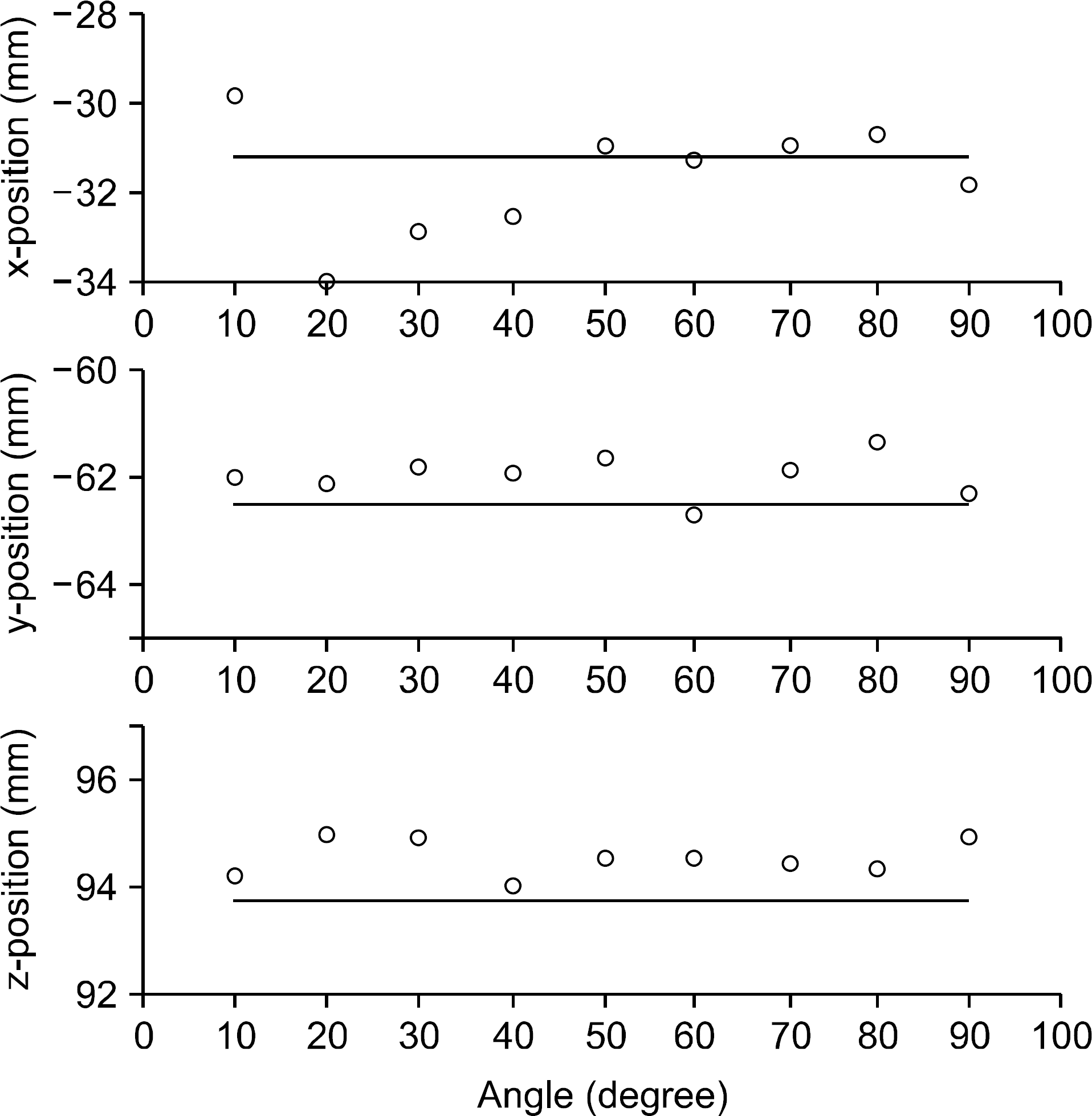
Fig. 7.
Position estimation error in each x, y, z direction and the three dimensional distance error of the fiducial at (−31.25, −62.5, 93.75) in the lung with respect to the angular intervals between the two kV imaging systems.
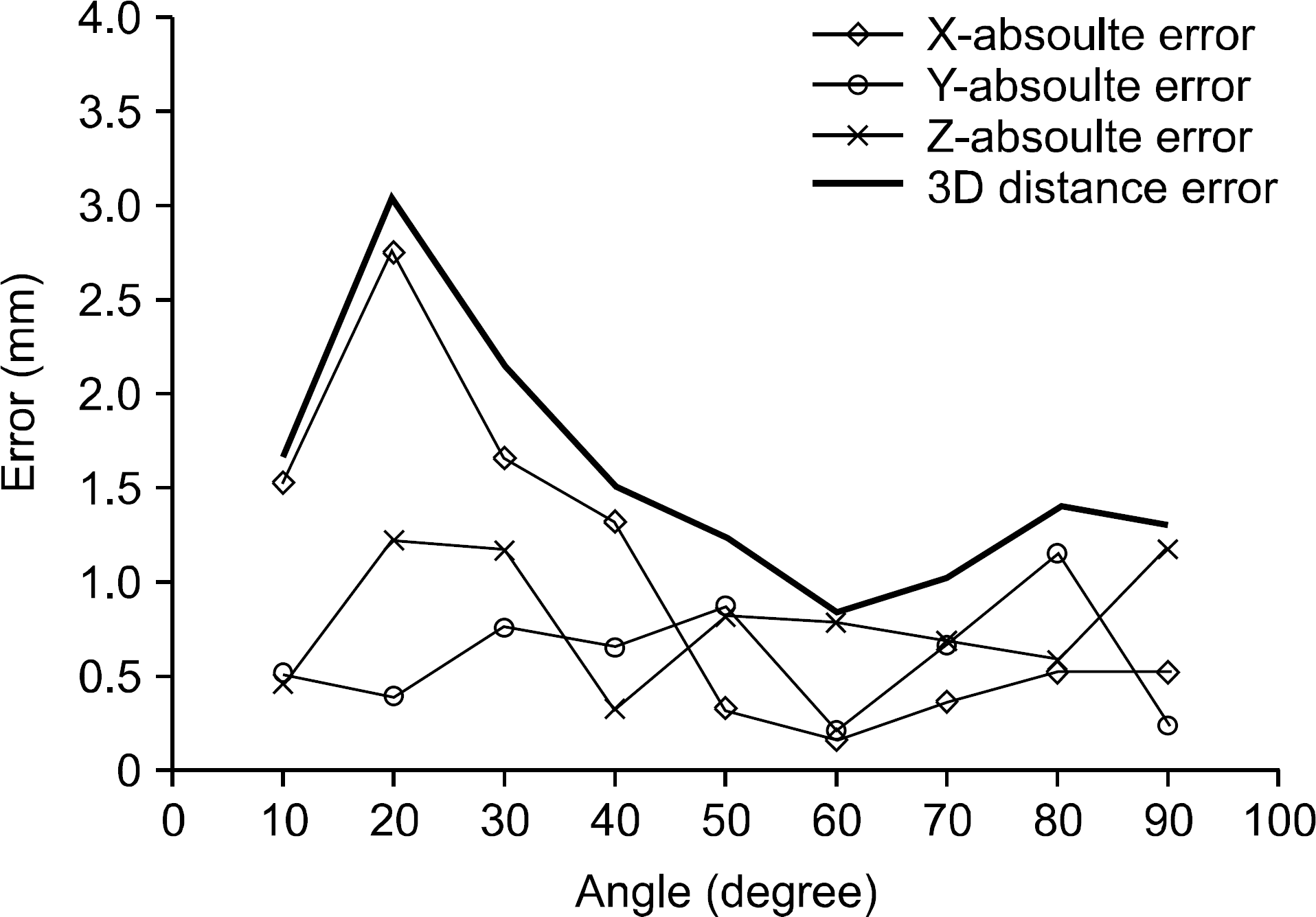
Fig. 8.
Influence of the detector resolution on the positional estimation of the fiducial at (−31.25, −62.5, 93.75) in the lung for different angular intervals between the two kV imaging systems.
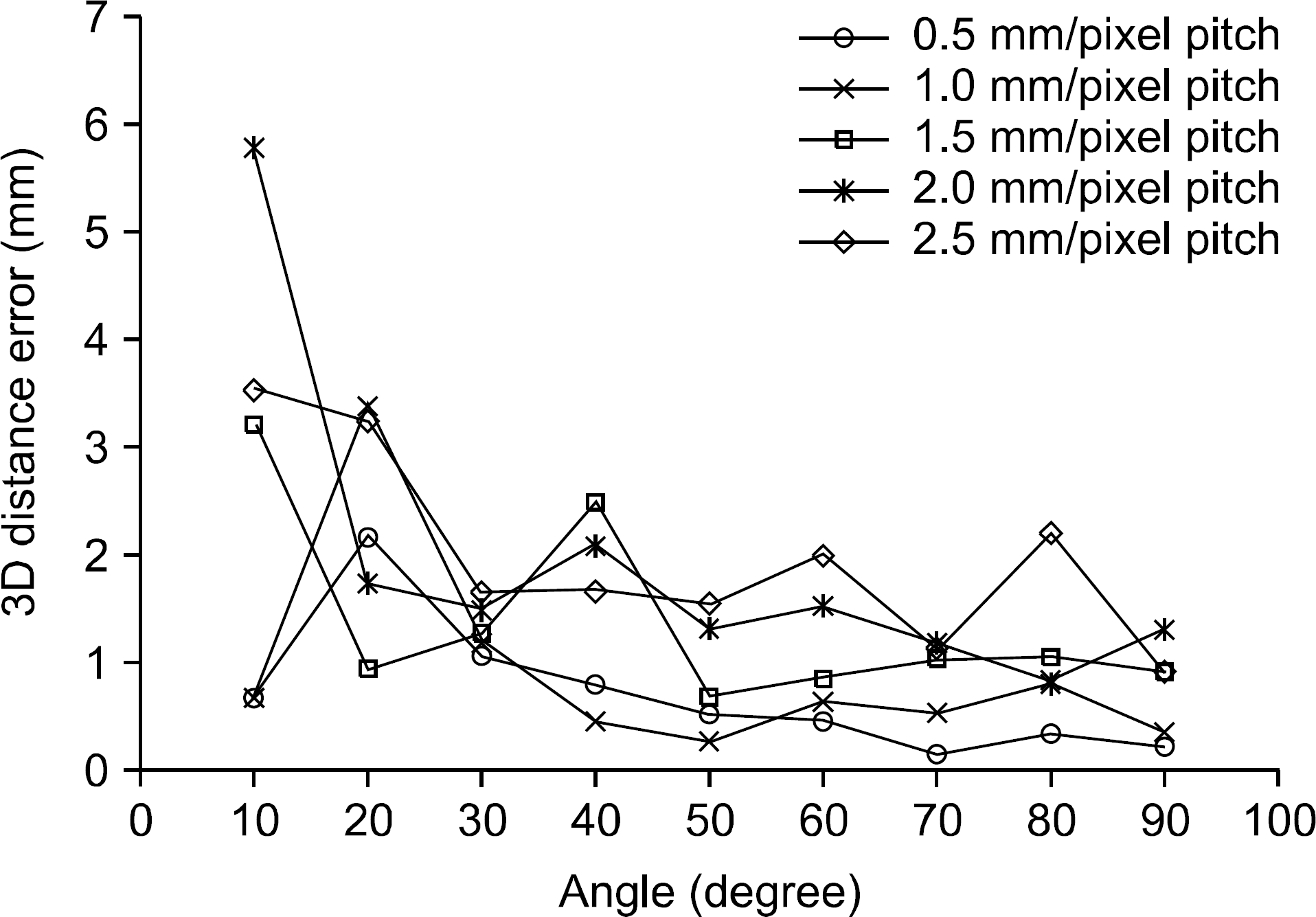
Table 1.
The phantom and projection condition in the X-CAT simulation.
Table 2.
The parameters used in the simulation. (a) Each projections are taken every 5o.
Table 3.
The dependence of the detector resolution on the three dimensional distance error in mm between the original metal marker position and the estimated position for the given angular intervals of the kV imaging systems.


 PDF
PDF ePub
ePub Citation
 Print
Print


 XML Download