Abstract
Recently, digital breast tomosynthesis (DBT) has been investigated to overcome the limitation of conventional mammography for overlapping anatomical structures and high patient dose with cone-beam computed tomography (CBCT). However incomplete sampling due to limited angle leads to interference on the neighboring slices. Many studies have investigated to reduce artifacts such as interference. Moreover, appropriate filters for tomosynthesis have been researched to solve artifacts resulted from incomplete sampling. The primary purpose of this study is finding appropriate filter scheme with FBP reconstruction for DBT system to reduce artifacts. In this study, we investigated characteristics of various filter schemes with simulation and prototype digital breast tomosynthesis under same acquisition parameters and conditions. We evaluated artifacts and noise with profiles and COV (coefficinet of variation) to study characteristic of filter. As a result, the noise with parameter 0.25 of Spectral filter reduced by 10% in comparison to that with only Ramp-lak filter. Because unbalance of information reduced with decreasing B of Slice thickness filter, artifacts caused by incomplete sampling reduced. In conclusion, we confirmed basic characteristics of filter operations and improvement of image quality by appropriate filter scheme. The results of this study can be utilized as base in research and development of DBT system by providing information that is about noise and artifacts depend on various filter schemes.
References
1. National Cancer Information Center:. 2009.
2. Smith A. Full field breast tomosynthesis, Radiol Manage, Vol. 27 (. 2005. ), pp.25–31.
3. Kim Ys. Park HS, Choi JG, et al. Comparison of digital mammography and digital breast tomosynthesis, Prog Med Phys, Vol. 23 (. 2012. ), pp.261–268.
4. Shon CS, Cho MK, Limv CH, Cheong MH, Kim HK, Lee SS. Enhancement of image sharpness in x-ray digital tomosynthesis using self-layer subtraction backprojection method, Journal of the Korean Society for Nondestructive Testing, Vol. 27 (. 2007. ), pp.8–14.
5. Lauritch L, Haerer WH. A theoretical framework for filtered backprojection in tomosynthesis. SPIE, Vol. 3338 (. 1998.
6. Dobbins III JT, Godfrey DJ. Digital x-ray tomosynthesis: currect state of the art and clinical potenctial. Phys. Med. Biol, 48, R65 (. 2003.
7. Sechopoulos I. A review of breast tomosynthesis. Part Ⅱ. Image reconstruction, processing and analysus, and advanced applications. Med. Phys., 40 (1), (. 2013.
8. Mertelmeier T, Orman J, Haerer WH, Dudam MK. Optimizing filtered backprojection reconstruction for a breast tomosynthesis prototype device. SPIE, Vol. 61420F (. 2006.
9. Hu YH, Zhao B, Zhao W. Image artifacts in digital breast tomosynthesis: Investigation of the effects of system geometry and reconstruction parameters using a linear system approach. Med. Phys. 35:5242. 2008.

10. Youn H, Kim JS, Cho MK, Jang SY, Song WY, Kim HK. Optimizing imaging conditions in digital tomosynthesis for imageguided radiation therapy, Korean J Med Phys, Vol. 21 (3) (. 2010.
11. Cong L, Zhao W, Chen Y. Effects of slice thickness filter in filtered backprojection reconstruction with the parallel breast tomosynthesis imaging configuration. Proc. IEEE-International Symposium on Intelligent Biological Medicaine (. 2011.
12. Oh JE, Cho HS, Kim DS, Choi SI, Je UK. Application of digital tomosynthesis of optimal deblurring filters for dental X-ray imaging. JKPS (. 2012. ), p.1161–1166.
13. Mertelmeier T. Filtered backprojection-based methods for tomosynthesis image reconstruction. I. Reier, S. J. Glick: Tomosynthesis imaging, Taylor & Francis, New York (. 2014. ), pp.101–106.
14. Gonzalez RC, Woods RE. Digital imaging processing: international edition, 3rd, Pearson Eduation, NJ (. 2002.
15. Lee S, Lee CL, Cho HM, et al. Effects of reconstruction parameters on image noise and spatial resolution in cone-beam computed tomography, JKPS, Vol. 59 (. 2011. ) pp.2825–2832.
Fig. 2.
(a) A schematic illustration of simulated phantom and (b) in-plane and out-of plane of ball phantom.
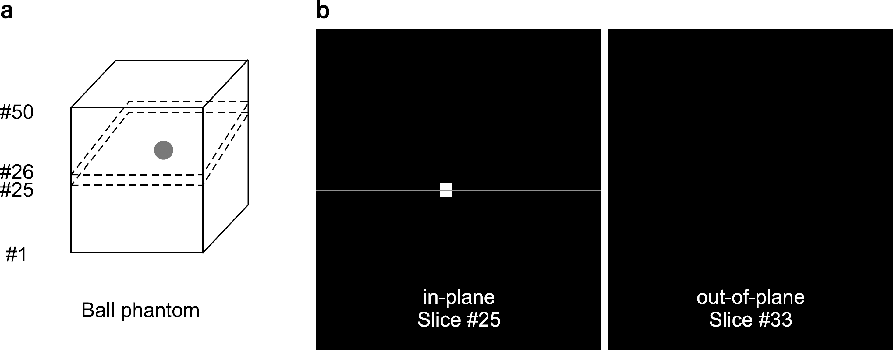
Fig. 3.
(a) Sampled region in the frequency domain by the Fourier slice theorem, and (b) a schematic illustration of slice thickness filter in z-direction frequency that can be used to improve artifacts resulted from missing data.
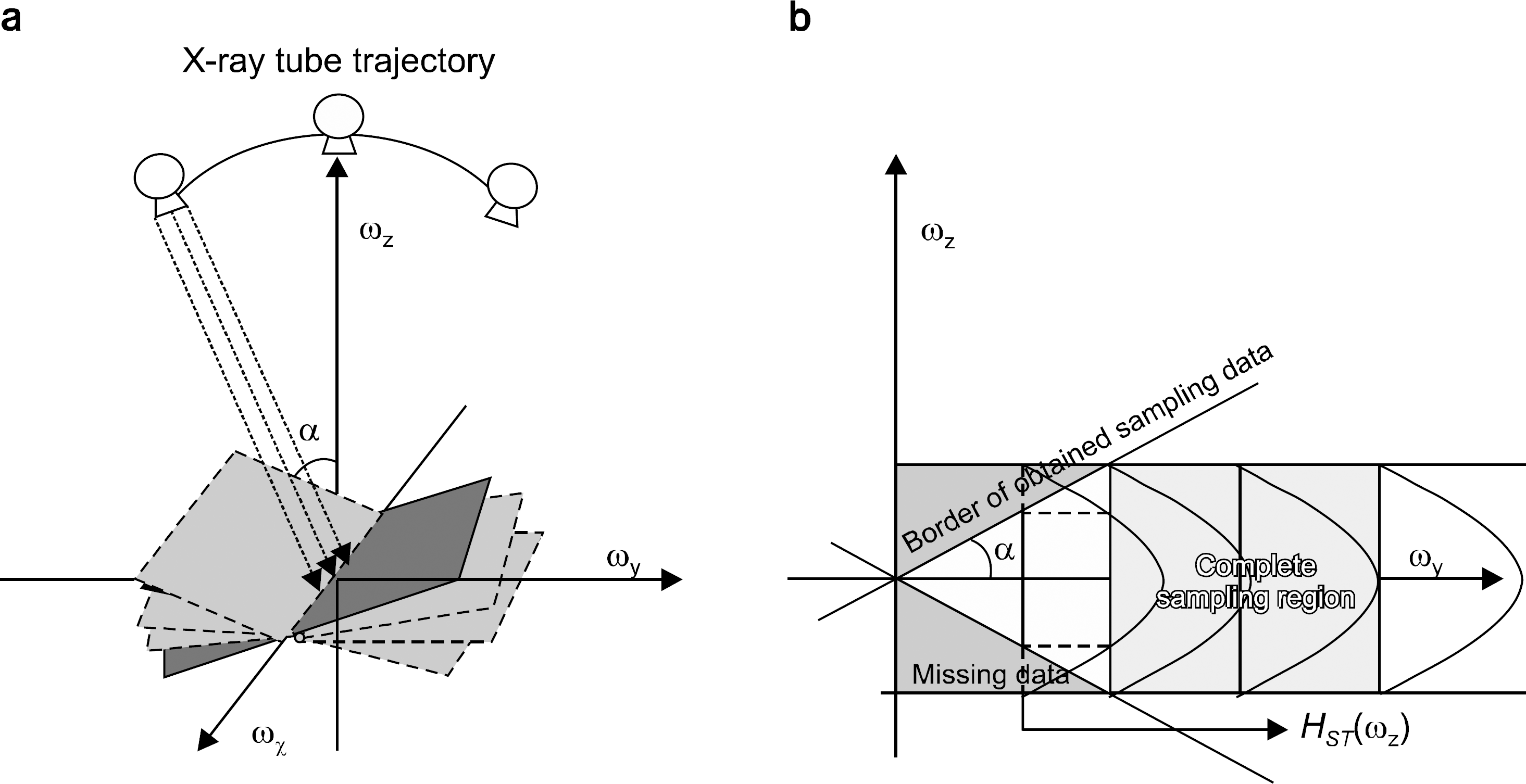
Fig. 6.
Reconstructed images of ball phantom with filter scheme (a) 5, (b) 6, (c) 7, and (d) 8. The in-plane slices through the balls center, and the out-of-planes with distance of 8 mm were shown.
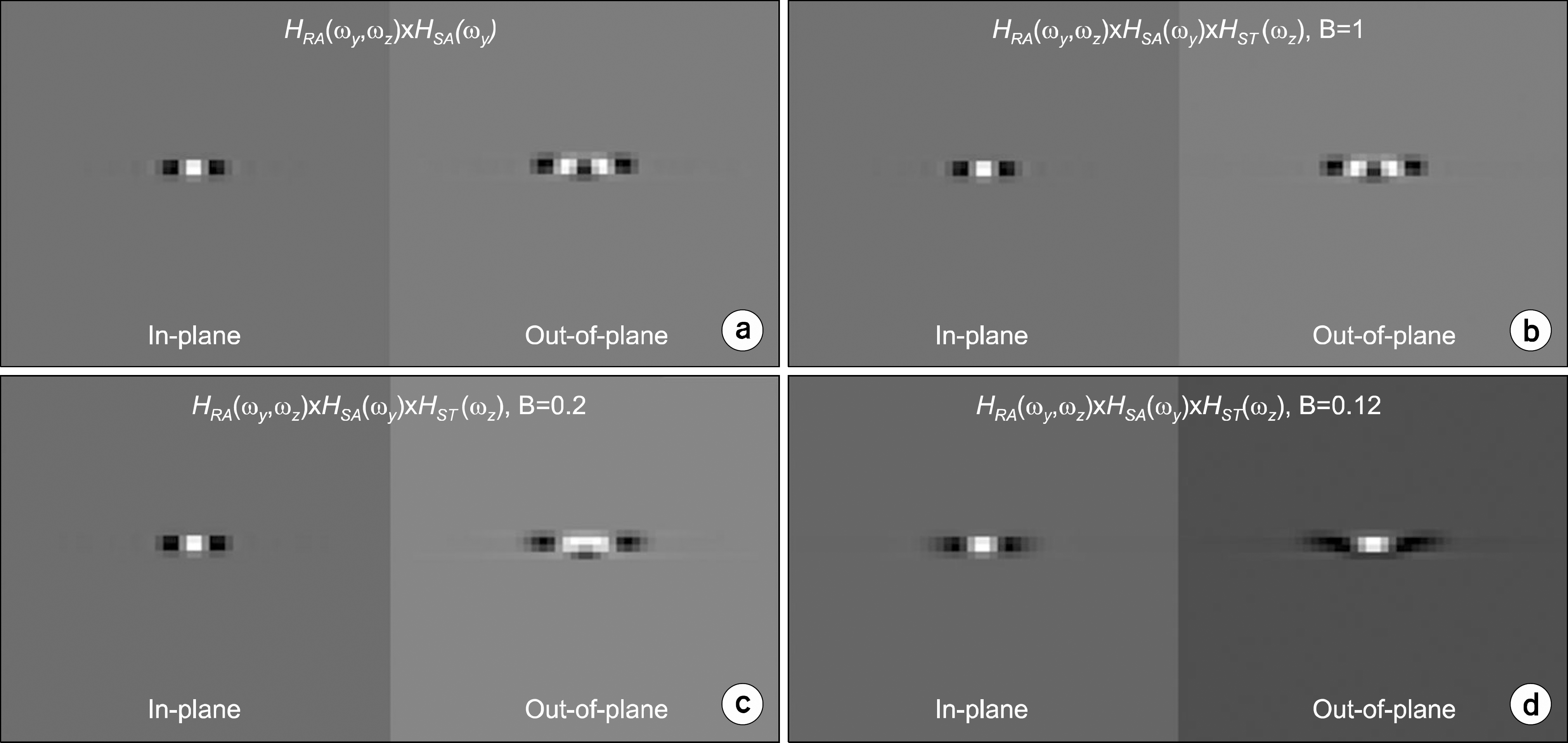
Fig. 7.
Profiles through line #25 of reconstructed slice #25 and #33 with filter scheme (a) 5, (b) 6, (c) 7, and (d) 8. The normalized profiles in the slice #25 through the object (z=0) were drawn with black lines, the profiles for the slice #33 (Z=8 mm) with red lines.
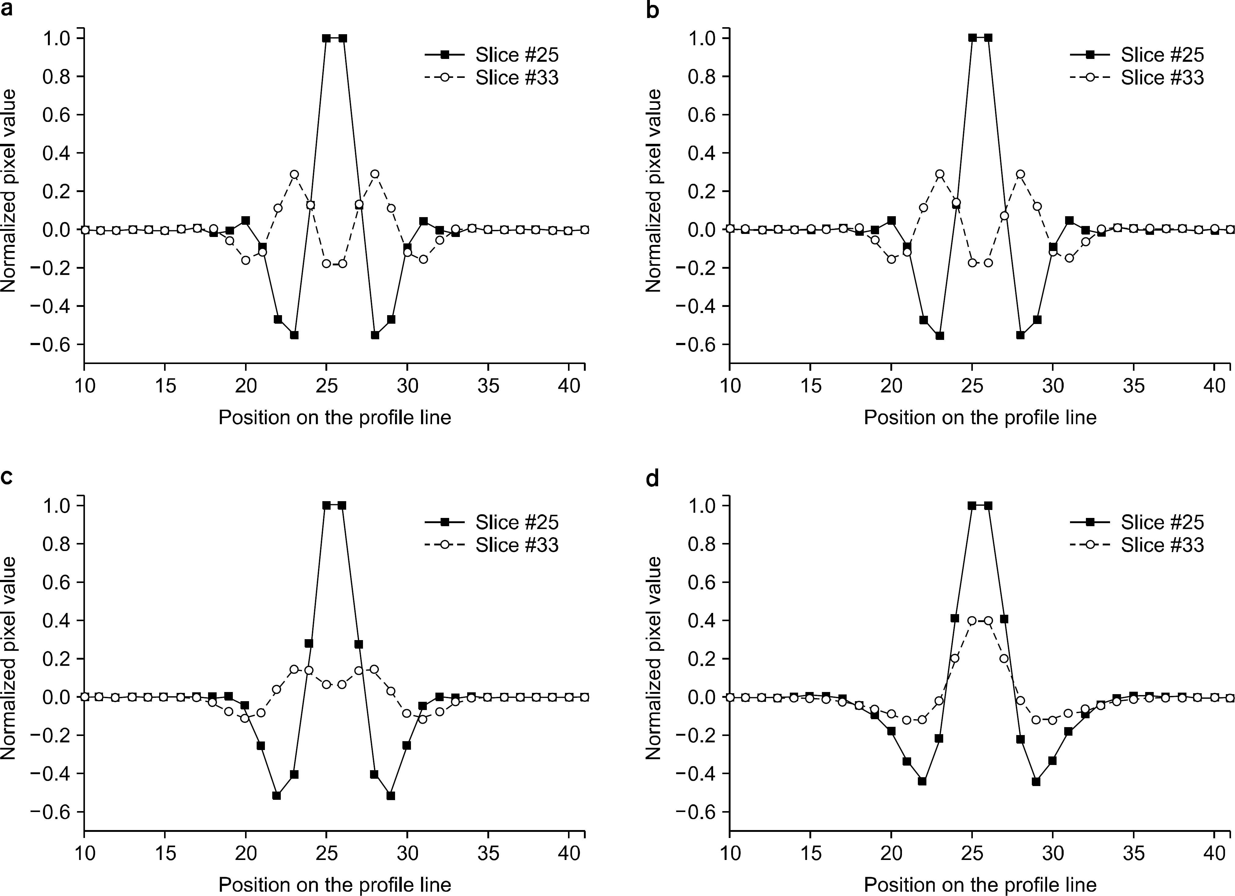
Fig. 8.
Central slices of breast phantom reconstructed with filter scheme (a) 1, (b) 2, (c) 3, and (d) 4.

Fig. 9.
The reconstructed images of breast phantom. The in-planes (slice #17) reconstructed with filter scheme (a) 5, (c) 6, (e) 7, and (g) 8. The out-of-planes (slice #25) reconstructed with filter scheme (b) 5, (d) 6, (f) 7, and (h) 8.

Table 1.
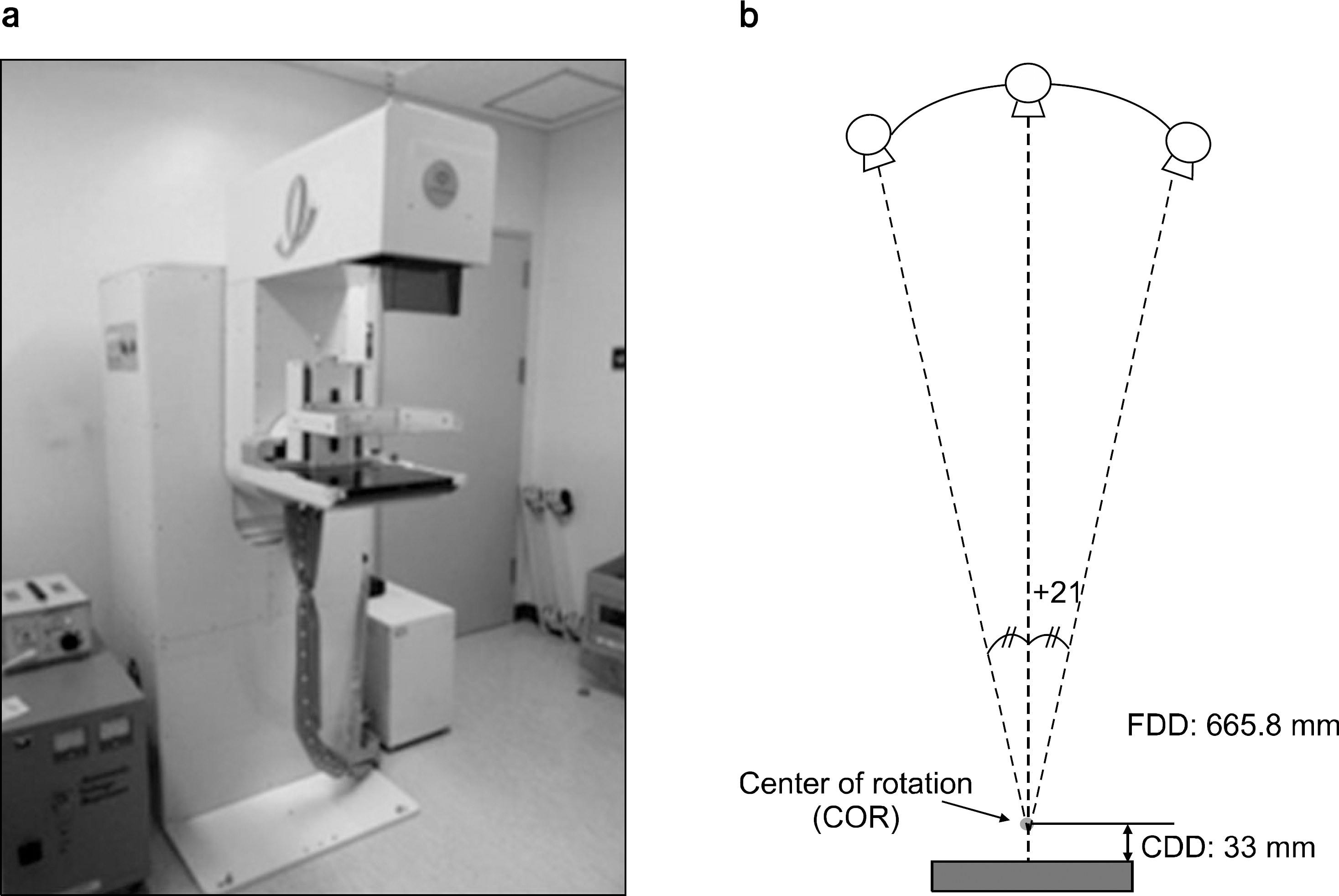
Specification of used DBT system.
Table 2.
Summary of used reconstruction filter schemes.


 PDF
PDF ePub
ePub Citation
 Print
Print



 XML Download