Abstract
The IMRT is proper implement to get high dose deliver to tumor as its shape and selective approach in radiation therapy. Since the IMRT is performed as modulated the radiation fluence by the MLC created the open shapes and its irradiation time, the dose of segment of radiation field effects on the cumulated portal dose. The accurate output factor of small and step shape of segment is important to improve the determination of deliver tumor dose as it is directly proportional to dose. This experiment performed with the 6 MV photon beam of Clinac Ex(Varian) from 3×3 cm2 to 0.5×0.5 cm2 small field size for collimator jaw in MLC free and/or for MLC open field in fixed collimator jaw 10×10 cm2 using the CC01 ion chamber, SFD diode, diamond detector and X-Omat film dosimetry. As results of normalized to the reference field of 10×10 cm2 of MLC, the output factor of 3×3 cm2 showed 0.899±0.0106, 0.855±0.0106 for 2×2 cm2, 0.764±0.0082 for 1×1 cm2 and 0.602±0.0399 for 0.5×0.5 cm2. The output factor of MLC open field has shown a maximum 3.8% higher than that of the collimator jaw open field.
Go to : 
REFERENCES
1. Klein EE, Hanley J, Bayouth J, et al. Task Group 142 report: Quality assurance of medical accelerators. Med Phys. 36(9):4197–4212. 2009.
2. Barbosa NA, Rosa LAR, et al. Development of a phantom for dose distribution verification in Stereotactic Radiosurgery. Physica Medica. 29:461–469. 2013.

3. Thomas SJ, Eaton DJ, et al. Equivalent squares for small field dosimetry. The British Journal of Radiology. 81:897–901. 2008.

4. Choi TJ, Kim JH, Kim OB, et al. Development of a New Radiotherapy Technique using the Quasi-conformation Method. J Korean Soc Ther Radiol. 9(2):343–350. 1991.
5. Kenichiro Hasumi, Yukimasa Aoki, Ryuko Wantanabe, Dean L Mann. Clinical respondse of advanced cancer patients to cellular immunotherapy and intensity-modulated radiation therapy. Oncoimmunology. 2(10):2013.
6. Cadman P, Sidhul NPS, Ibbott G, Nelson A. Dosimetric considerations for validation of sequential IMRT process with a commercial treatment planning system. Phys Med Biol. 47:3001–3010. 2002.
7. Alfonso R, Andreo P, Capote R, et al. A new formalism for reference dosimetry of small and nonstandard fields. Medical Physics. 35:5179–5186. 2008.

8. Francescon P, Cora S, Cavedon C. Total scatter factors of small beams: A multidetector and Monte Carlo study. Medical Physics. 30:341–347. 2003.

9. Oh SA, Kang MK, et al. Study of the Penumbra for High-energy Photon Beams with GafchromaticTM EBT2. Journal of the Korean Physical Society. 60(11):1973–1976. 2012.
10. Varian medical system. Eclipse Algorithms Reference Guide. p43-45. 2009.
11. Francisco SD, Günther HH, Javier P, et al. Uncertainty estimation in intensity-modulated radiotherapy absolute dosimetry verification. Int J Radiation Oncology Biol Phys. 68(1):301–310. 2007.
12. Alfonso R, Andreo P, Capote R, et al. A new formalism for reference dosimetry of small and nonstandard fields. Medical Physics. 35:5179–5186. 2008.

13. Das IJ, Ding GX, Ahnesjo A. Small fields: Nonequilibrium radiation dosimetry. Medical Physics. 35:206–215. 2008.

14. Followill DS, Kry SF, Qin L, et al. The Radiological Physics Center's standard dataset for small field size output factors. Journal of Applied Clinical Medical Physics. 13(5):282–289. 2012.

15. Scott AJD, Nahum AE, Fenwick JD. Using a Monte Carlo model to predict dosimetric properties of small radiotherapy photon fields. Medical Physics. 35:4671–4684. 2008.

16. Das IJ, Ding GX, Ahnesjo A. Small fields: Nonequilibrium radiation dosimetry. Medical Physics. 35:206–215. 2008.

17. Gavin CS, Steve W, Narinder PS, et al. Experimental small field 6 MV output ratio analysis for various diode detector and accelerator combinations Radiotherapy and Oncology. 100:429–435. 2011.
18. Duggan DM, Coffey CW II. Small Photon Field Dosimetry for Stereotactic Radiosurgery. Medical Dosimetry. 23(3):153–159. 1998.

Go to : 
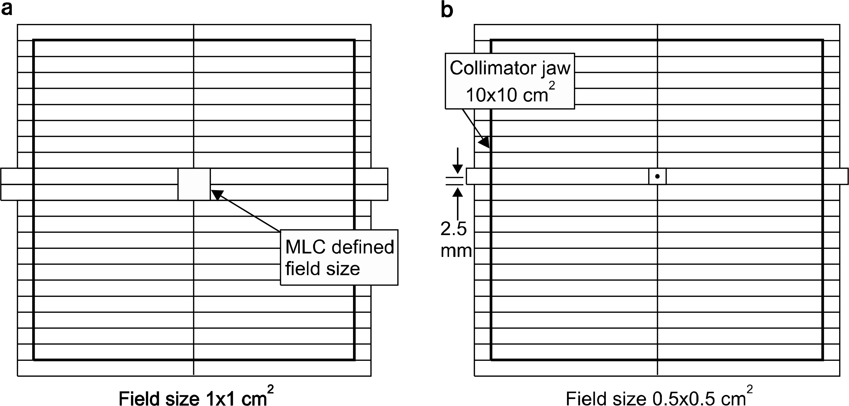
 | Fig. 1.Showing the small field size of MLC in cm for 10×10 cm2 collimator jaw. The pictures showed (a) 1×1 cm2 and (b) 0.5×0.5 cm2 on SAD 100 cm and SPD 95 cm. |
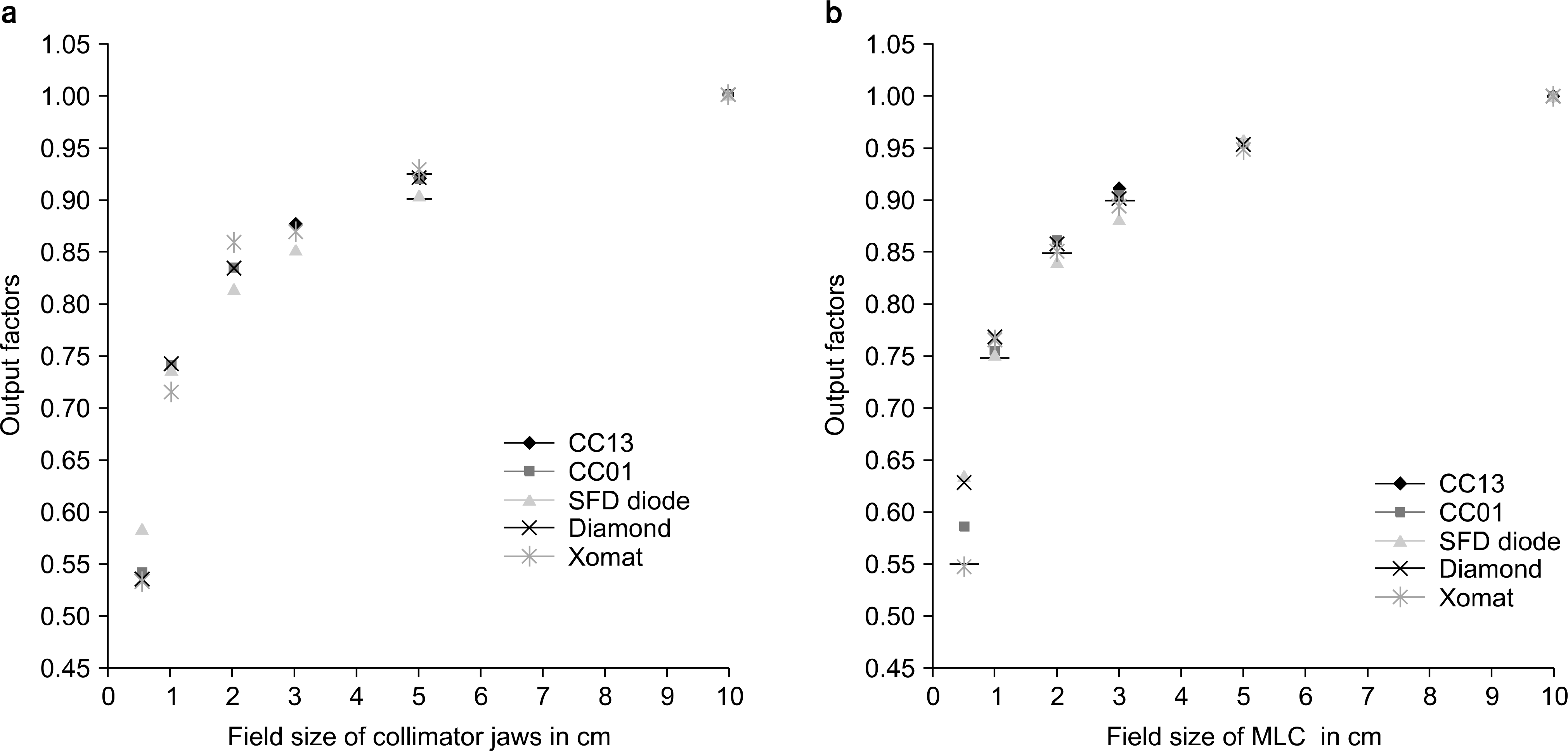
 | Fig. 2.Showing the output factors of small fields in 6 MVX rays using the SFD diode, Xomat film, diamond chamber and CC13 ion chamber used for reference output dose. The field size delivered from the collimator jaws in cm for MLC free (a) and the MLC open in collimator jaws set of 10×10 cm2 (b). |
Table 1.
The averaged output factors obtained as function of the collimator field size for the MLC free.
| Jaw field (cm2) | Output factor∗ | |
|---|---|---|
| MLC free | 10×10 | 1.000±0.0000 |
| 5×5 | 0.920±0.0100 | |
| 3×3 | 0.866±0.0093 | |
| 2×2 | 0.830±0.0096 | |
| 1×1 | 0.741±0.0022 | |
| 0.5×0.5 | 0.550±0.0240 |
Table 2.
The averaged output factors obtained as function of the MLC field size for the Collimator 10×10 cm2.
| MLC field (cm2) | Output factor∗ | |
|---|---|---|
| JAW 10×10 cm2 | 10×10 | 1.000±0.0000 |
| 5×5 | 0.955±0.0035 | |
| 3×3 | 0.899±0.0106 | |
| 2×2 | 0.855±0.0106 | |
| 1×1 | 0.764±0.0082 | |
| 0.5×0.5 | 0.602±0.0399 |
Table 3.
Comparison the output factors of experiments to that of derivered' from TPS.


 PDF
PDF ePub
ePub Citation
 Print
Print


 XML Download