

 PDF
PDF ePub
ePub Citation
 Print
Print


INTRODUCTION
Marginal fit is one of the most important parameters for achieving longevity in prosthodontic treatment. Marginal discrepancy is detrimental both to the tooth and to the supporting tissues because it generates microfiltration, favors the dissolution of cement, and increases bacterial plaque retention. It is also predisposed to the appearance of secondary caries and subsequent pulp inflammation, modifying the distribution of microflora and inducing the appearance of periodontal disease.123
Various authors agree that a mean discrepancy of below 120 microns is clinically acceptable. In vitro studies have proposed levels ranging between 50 and 200 microns but many researchers now use the 120 µm maximum limit set by McLean and Von Fraunhofer.14
Computer-aided design and computer-aided manufacturing (CAD/CAM) systems are becoming increasingly popular today due to their precision and also due to the demand for prostheses made with aesthetic materials like zirconium dioxide.2 Reich et al.5 reported an average marginal discrepancy of 80 µm in zirconium restorations made with CAD/CAM using the Lava system 3M ESPE.
CAD/CAM technology has established itself in dentistry today by providing higher accuracy for the finishing of restorations than conventional methods. The cost of the technique is offset by the time savings both in the dental clinic and in the dental laboratory.6
Today, extraoral scanning is a common laboratory procedure. Normally, it involves scanning the master models after pouring the impressions of dental preparations made in the dental office. However, with the introduction of high precision scanners, extraoral scanning can also be performed with data from conventional impressions; this means that the plaster model stage can be dispensed with, thus avoiding the errors that may be caused by the expansion during setting.
During direct intraoral scanning, there is a margin of error of 14 to 21 µm for capturing the image.6 Various studies have shown that the same scanners perform the scan with greater precision on a master model than in the intraoral medium.6 It has also been demonstrated that the marginal fit is higher in crowns obtained from digital impressions than in those obtained from conventional impressions.467
In an in vivo study, Syrek et al.8 obtained a total mean marginal discrepancy of 49 µm with intraoral digital impression and 71 µm with conventional impression for single zirconium dioxide crowns. Ng et al.9 reported mean vertical marginal gaps of 48 µm for digital impressions and 74 µm for conventional impressions in lithium disilicate crowns.
Currently, some highly precise extraoral digital impression techniques are available that present highly similar results for marginal fit. The results are even better when compared with those of intraoral digital impressions when longer lengths in the arch are scanned. High precision extraoral scanning techniques and equipment can obtain results as good as those achieved with intraoral scans when scanning long lengths of dental arches; in the study by Flügge et al.,10 the precision obtained with the extraoral scan was twice as high.10 Some of the factors that may cause the large deviation in intraoral scanning are the movement of the patient and of the operator's hand during the scanning process, the limited intraoral space, and the moisture attributed to oral fluids.610
Many studies have reported data on the comparison between intraoral and extraoral digitization, but only one analyzed the differences between the digitization of silicone impressions and plaster model casts from the same impressions in order to assess the errors accumulated in the two phases.11
The objective of the present study was to compare marginal discrepancy in milled monolithic yttrium stabilized zirconium dioxide (YSZD) crowns manufactured by the digitization of the silicone impressions and in crowns created by the digitization of the working cast from the same impressions.
The null hypothesis is that there are no significant differences between both groups and that the step of pouring silicone impressions can be omitted from the protocol for making zirconium dioxide crowns with CAD/CAM systems.
Go to : 
MATERIALS AND METHODS
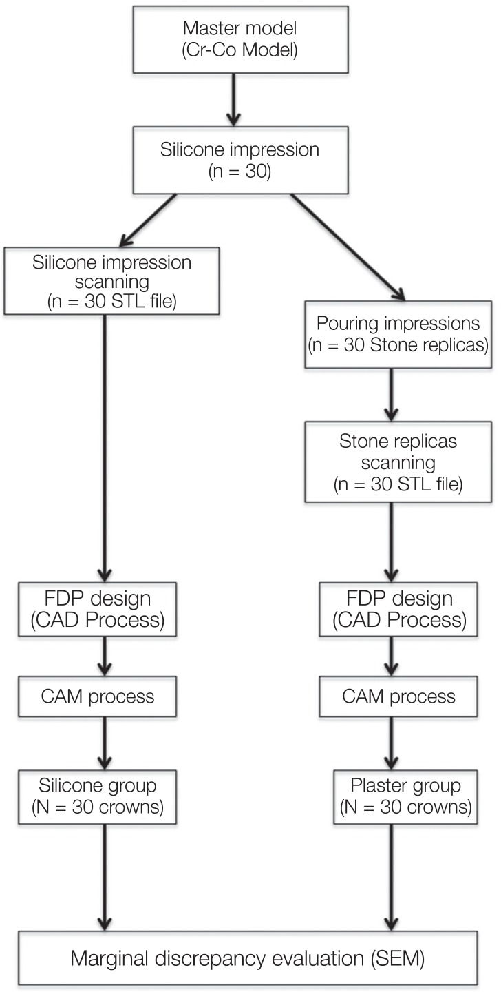
This is an in vitro study of two groups of milled monolithic YSZD crowns manufactured using different types of extraoral digital impression: scanned from a silicone impression or scanned from a working cast obtained from the same silicone impression (Fig. 1).
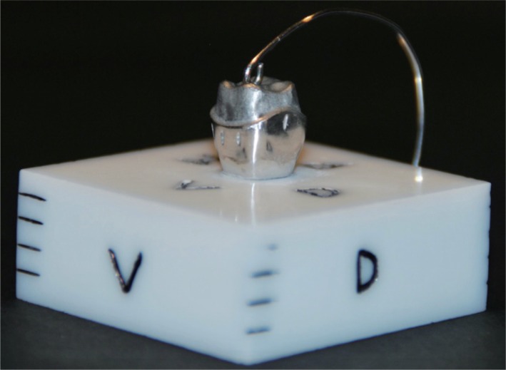
Previously, a model of an upper left first molar sculpture was manufactured in the laboratory in Cr-Co, fixed in a base of totally sintered zirconium dioxide (ZrO2) (Fig. 2). The preparation design of the model included a circumferential chamfer with an angle of convergence of approximately 6°. Various authors consider this preparation to be the most suitable for monolithic YSZD restorations.121314
In order to study the marginal adaptation of the crowns, central marks were made on each of the 4 sides of the metallic master model, in this way the microscope observation reference points were the same for all the crowns. 12 measurements were taken in the entire perimeter of each crown (3 measurements in each reference mark of the 4 sides of the master model). Both the master model and the crowns under study were designed and manufactured in the same laboratory (Dencadigi Dental 3D Consulting, Cornellà de Llobregat, Barcelona, Spain) and always by the same prosthesis technician using a computer (Inspiron desktop computer 3847 DELL, China), a laboratory scanner (Identica Blue, Medit, Korea), software (Exocad, 2014. 02 Version, Darmstadt, Germany), a 5-axis dental milling machine (DWX-50, Roland, Japan), and a sintering furnace (BIOKER LT 1550).
The preparation followed the manufacturers' instructions. The laboratory technician was blind to the purpose of the study.
A sample size of 30 individuals per group allows to detect differences of 0.5 times the square root of the sum of variances with a level of significance of 5 % and a power of 80%.
For the selection of groups, thirty poly-vinyl poly-vinyl siloxane impressions of the master die were made with low viscosity poly-vinyl siloxane material (Turboflex, R&S, Light Normal Set, Tremblay, France) ISO 4823, and high viscosity poly-vinyl siloxane material (Turboflex, R&S, Putty Soft Normal Set, Tremblay, France) ISO 4823. Small perforated plastic cups (diameter 30 mm, height 20 mm) were used as impression trays and the master die was adjusted to be centered in the middle of the cup.
The manufacturer's instructions were followed for the setting time of the impression material, and the master die was then removed from the impression. For each impression, the two components of high viscosity poly-vinyl siloxane material (base and catalyser) were mixed, always in the same quantity (half of the measuring spoons), and were placed in the container. The low viscosity poly-vinyl siloxane material was applied to the tip of the syringe over the metal die. After five seconds, the container full of high viscosity silicone was placed on the covered die of low viscosity silicone. After five minutes, the setting time recommended by the manufacturer, the container was removed from the die and the overflowing material cut with a scalpel and sterile sheet (AesculapDivision, B. BRAUN, Tuttlingen, Germany) complying with ISO 11607.
Each of the silicone impressions was numbered with a permanent marker on each container in the order of production from 1 to 30. To facilitate the spatial recognition of the impression during scanning, the buccal aspect was marked with a V, the palatal aspect with a P, the distal aspect with a D, and the mesial aspect with an M.
In this study, we used the Helling 3D Scan Spray (Helling GmbH, Heidgraben, Germany), which complies with ISO 9001, to scan 30 silicone impressions. The impressions were sprayed in a uniform minimum thickness covering of fine-grained TiO2 particles (average particle size 2.8 microns), which was easy to remove.
The 30 impressions were sent to the laboratory and were scanned within six hours. Immediately, type IV stone (Hebohard, Hebör Spain SA) (ISO 6873) was mixed according to the manufacturer's instructions and poured into the impressions. Type IV stone is recommended when high levels of strength and hardness and low setting expansion is required. In this case, according to the manufacturer, the expansion is 0.25%, compression resistance is 60 N/mm2, and the setting time is 12 – 15 minutes. This type of cast is known as “master cast” and is used in high-precision fixed prosthodontics.
In the Computer Aided Design (CAD) Phase, with its structured light, Identica Blue scanner is able to scan impressions, plaster models, implants, and even small accessories (ISO 12836). The use of blue light rather than white light means that this scanner has a shorter wave length and achieves much more accurate scans than other similar instruments.
The scanner, calibrated prior to the start of the study, was connected to a PC with Exocad software, in accordance with ISO 9001 and 13485, which is often used in open CAD/CAM dental systems. The three-dimensional image obtained was confirmed and the restoration was designed. The computer file format for computer-aided design, which defines the geometry of 3D objects, represents the object through a grid of small triangles; this type of format is called STL (StereoLithography). Each STL file was saved with the name of each of the impressions and its numbering; thus, S1 was the name for “Silicone Scanner number 1”.
Later, using the Exocad software, the restoration was designed (the CAD process) with the following steps: 1. setting of the scanner data, 2. recognition of the line termination preparation, 3. recognition of the base of the crown, 4. tooth location, 5. free design (specifying the thickness of the crown, in this case 0.6 mm, and the cementing space of 80 microns, not modifiable using the software, following the manufacturer's technical specifications regarding its system and software), 6. adaptation to the antagonist (not applicable in this case), and 7. trusmile (final restoration).
In accordance with the manufacturer's instructions, the minimum reduction of the substance for the preparation of monolithic crowns is 0.5 to 0.7 mm in the occlusal zone and 0.5 mm in the contour of the preparation. However, this process of manufacturing monolithic crowns with minimal reductions of the dental substance, which previously could be achieved only with metal crowns, should be performed with a careful selection of the color of the structure and should be characterized with an individual makeup.15
In the CAM Phase (Computer Aided Manufacturing), once the design the design of the restoration was complete, the manufacturing process began (CAM Process). The information on the crown designed in the CAD process was imported from the PC to the milling machine, along with the blank properties, the material chosen, and the strategy or set of paths necessary to perform the milling.
Blanks of zirconium dioxide previously pressed and presintered were inserted at a magnification of 25% to compensate for the contraction suffered during the sintering in accordance with the manufacturer's instructions. This material was prepared to mill the crown to total volume as a monolithic material.
With the blank inserted and all the information processed, the DWX-50 miller (ISO 14001 and 9001) was used to perform the (mechanized) milling through the following stages: smoothing down (2 mm mill), finishing (1 mm mill) and superfinishing (0.5 mm mill).
To take advantage of the disk material, all the impressions were scanned and designed. Then, various crowns were milled at a time, each one designed so that its initials were milled on the inner side of one of the palatal cusps (S1, S2… S30). Once the milling was completed, the disk was removed and the crowns separated. After milling, the specimens were sintered at 1580℃ for 5.5 hours in the furnace.
The CAD/CAM process described above was repeated for the group was repeated for the group of crowns made by scanning the casts obtained after the pouring of the 30 previously scanned silicone impressions. The impressions were always poured by the same technician manually. The casts were made with type IV stone (Hebohard, Hebör Spain SA) ISO 6873 with powder/liquid ratio of 100 g/20 mL according to the manufacturer's instructions, mixed in a vacuum mixing machine. After 60 minutes (the setting time stipulated by the manufacturer is 15 minutes), the plaster models were withdrawn from the impressions and were immediately scanned. As noted above, the use of TiO2 spray required in silicone impressions was not needed. In the crowns in this second group, the initials of the plaster were also milled on the inner side along with their number (Y1, Y2… Y30). For the manufacture of the 60 crowns, four disks (Bioker, HT, Oviedo, Spain), made in accordance with ISO 13485, were used: zirconium dioxide blanks (YSZD) of high translucency presinterized for dental application. After sintering, the finishing of the 60 crowns was performed; the rest of the sprues were removed and the crowns were polished with a rubber drill kit.
For the study of the specimens the analysis of vertical marginal discrepancy with scanning electron microscopy was performed. The marginal fit of the restorations was studied at the ICCTUB (Centres Cientifics i Tecnològics de la Universitat de Barcelona) (Scientific and Technological Services, University of Barcelona) using the scanning electron microscopy (SEM) FEI QUANTA 200 (date of the last calibration 09-02-2015).
The samples were analyzed in low vacuum mode without the need for prior preparation such as metallic or critical point drying. In this way the characteristics of the master die and crown were not altered.
To reduce intra-rater variability, the rater was duly trained before the beginning of the study. By marking the exact point on the master model where the measures were to be made, the subjectivity of the measurement was minimized. At this point, 3 data were taken in an area of 300 microns on the four aspects (measurements: 1, 2, 3) at ×600.
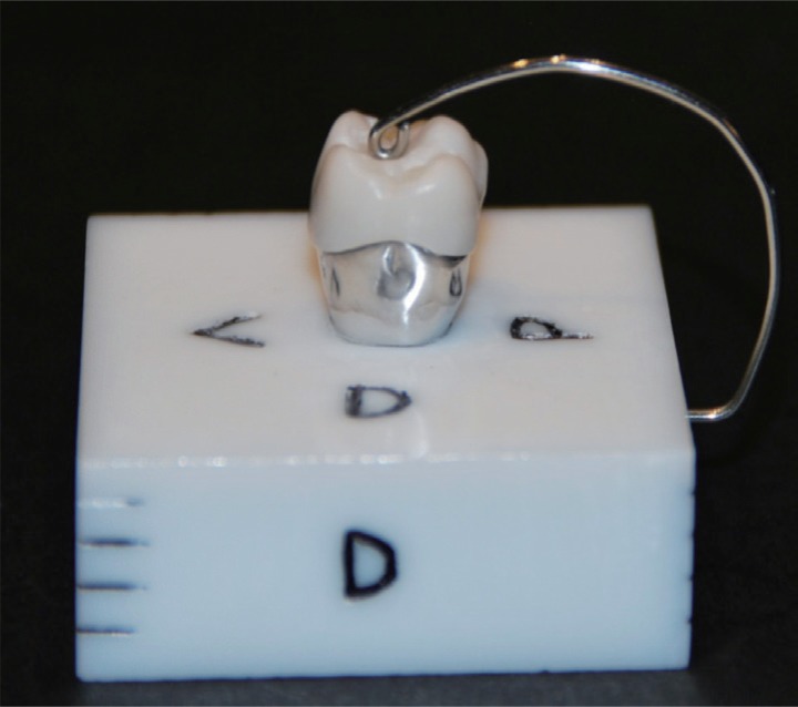
Fixing the specimens to the master cast. To be able to position each crown on top of the same die and to conduct measurements, a fixation was made on the zirconium base where the metallic die was incrusted, consisting of stainless steel wire elastic of Ø 0.8 mm - 032” Leowire C0400-08 Leone, in accordance with ISO 9001 and ISO 13485, arched so that the palatal aspect emerged from the base up to the centre of the crown (Fig. 3). The pressure of the fixation was checked before each crown was added to the die, checking that an 8 µm portion of Arthus articulating paper was retained by the wire so as not to allow any movement without tearing.
Once the fixation of the crown on top of the metallic die was checked, the whole set of samples was added (zirconium dioxide base with incrusted metallic die + fixed crown) on top of the microscope slide at an angle of 90 degrees. Therefore, the microscope would show the specimen, positioning the marginal interface to be studied perpendicularly on the ocular axis.
The microscope was configured in low vacuum conditions with a chamber pressure of 0. 98 torr and with the Large Field Detector (LFD) of FEI.
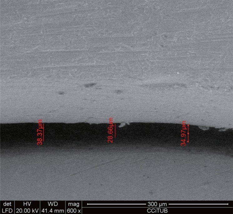
Data recording. All the observations were made using 20 KV acceleration voltage of the electron beam and at a working distance of 40 mm. Once the image was focused at a magnification of ×600, it was frozen and measurements were taken with the integrated software on the same microscope computer equipment. Each of the images was photographed and saved on the PC hard disk (Intel Pentium 4 XW4300 Workstation HP) connected to the computer equipment of the microscope (another Intel Pentium 4 XW4300 Workstation HP computer) (Fig. 4).
All measurements were made by the same operator who did not know which crown was being analyzed. Once the measurements of each crown were performed, the mark milled in one of the palatal cusps was read with a magnifying glass to identify it and to record the corresponding data.
The data collected from the 12 points of each crown were entered in a Microsoft Excel spreadsheet.
For the statistical study, the response variable is considered the marginal discrepancy from the master model. The mean measurement of the three points in each aspect has been taken as the response value. We considered each one of the 30 silicone impressions as the experimental unit, so the treatment group (scanning Silicone or scanning Plaster) and the aspect (M, V, D and P) were considered within subjects factors.
The data were log transformed in order to normalize the distribution.
A repeated measures ANOVA with two within subject factors was performed was performed to study significance of main factors and interaction. Sphericity has been checked and is satisfied by our data. The analysis was carried out with the package “ez”16 of the software R version 3.3.1.
Go to :
RESULTS
The means of the global marginal discrepancies for each group, without taking into account the aspects analyzed, were within clinically acceptable values, although the crowns from the silicone group presented higher discrepancy.
Comparing the means of each aspect of each crown in both groups, in the interproximal aspects (mesial and distal), the crowns in the silicone group present higher marginal discrepancy. Results are displayed in Table 1 for the different measuring sites per crown.
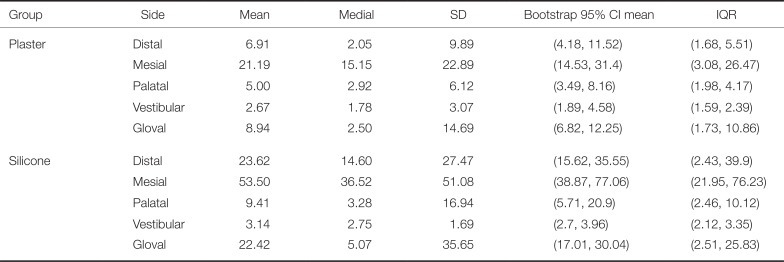
Table 1
Descriptive statistics of marginal discrepancy (in µm)
![]()
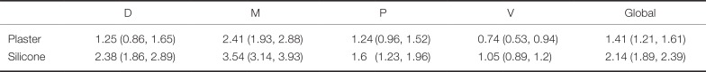
The statistical analysis (ANOVA) shows significant differences between the two groups (P < .001) and also between the four aspects (P < .001). Interaction is also significant (P = .0211), the Table 2 and the Figure 5 represents the results with the log-transformed data where vertical bars on the figure represent Fisher's Least Significant Difference (0.493).
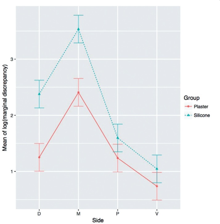 | Fig. 5Graph of the logarithm of the Marginal Discrepancy (in µm) variable of the Silicone group and the Plaster group. Significant differences (P < .05) between faces (M, D, V, and P) within each group, as well as between the groups (Silicone and Plaster), and the interaction between the two groups, specifically the mesial face, are presented.
|
Go to :
DISCUSSION
The choice of terminology to define the marginal fit is controversial. In 1989, Holmes et al.17 defined the relationship between the edge of the restoration and dental line termination in a standardized way. Their terminology is currently used as a reference to measure the marginal discrepancy.2
Although absolute marginal discrepancy is the most representative index, since it is the angular combination between the vertical and the horizontal marginal discrepancies, it is very difficult to gather all this information together in practice. Therefore, it was decided to analyze the marginal gap discrepancy described as the perpendicular measurement from the margin of the casting to the axial wall of the preparation.17 Although it is true that in some previous publication9 this measure is called vertical marginal discrepancy, due to possible terminations of the crown margin (overspread margin/under-extended margin) as explained by Holmes et al,17 from a view perpendicular to the margin of the crown the only data that can be determined using electronic microscopy is the marginal discrepancy in general, without being able to specify if the discrepancy is horizontal or vertical.
Within the limitations of this laboratory study, and as in other studies, the marginal discrepancies obtained after digitizing the silicone impressions and plaster models were clinically acceptable.141118
The results showed a high deviation in proximal aspects. Some studies of full arch scans conclude that the majority of the errors during the scan were associated with tessellation and height of the cusps.19 Normally, when studies are performed in vitro, researchers do not use anatomical models in laboratory tests because they have more control over the mechanical properties of the basic materials. However, this means that the effects of the restoration geometry on the distribution of tensions are excluded.20 In the case of this study, it was a master model that simulates a real dental preparation. Many authors have demonstrated that soft anatomy without major changes in curvature increases the precision of the digitization.1021
This theory is supported by Rudolph et al.,22 who used different digitization methods in an extraoral model to demonstrate that the shape of teeth was a determining factor for precision and that large deviations were found in areas with strong changes in curvature.22 This coincides with the data from Table 1, where the buccal (V) and palatal (P) aspects in both groups are the ones that obtain the best marginal fit. The digitization errors of the impressions are affected by the optical properties of the impression material and by the texture of the impression surface, a rough surface being more precise than a smooth one.21
Several studies have investigated the accuracy and reliability of the digitization of impressions and of the working models, comparing them with the digitization of the master models.111821 The aim was to assess the degree of error accumulated during the manufacturing steps of the crowns. Many of these studies are based on a single impression, scanning the same one multiple times, so the error due to performing conventional silicone prints is avoided.1623
In the present study, 30 silicone impressions were taken from the same master die and were poured, obtaining 30 “different” plaster models. Thus it not only evaluated the discrepancy due to the scan but the same situation was repeated several times.
Persson et al.18 performed the first investigations on discrepancies between scans of impressions and scans of plaster models through three-dimensional analysis with a software program that performed the comparison with colour maps.1118 Unlike the present study, these authors compared the virtual images of impressions and plaster models with virtual images obtained from scanning the master model, and concluded that there were no statistically significant differences between the results of the master model, the impression, and plaster groups. They also found that, in certain areas of the scan of the silicone impressions, the form of dental preparation influences the result; the scanning of canines and incisors was more accurate, and the scanning of the molars presented the greatest discrepancies.
Rudolph et al.22 evaluated three different CAD dental systems, concluding that the shape of tooth was the most critical factor that limits the accuracy.22 Coinciding with our study, they reported that the areas of large curvature changes obtained the largest deviations and were also related to the lower density of point-clouds, thus obtaining a lower degree of accuracy in the geometry of the curve zone.1822
Many of the results of the studies are influenced by the failure to use the same scanning systems for the groups under study.1824 This study eliminated this problem by using the same scanner for both silicone and plaster groups. The manufacturers of conventional dental scanners recommend the application of a spray with a titanium dioxide (TiO2) base to minimize the reflectivity of the plaster, or alternatively the use of a specially designed plaster for CAD scanning. However, scanners using blue LED, such as the one used in this study, have shown greater efficiency in recording images and do not require the use of sprays. Alghazzawi et al.3 showed that blue LED scanners do not require the use of a spray for improved image acquisition or the use of a specific scanning plaster, except for titanium abutments. However, although there is no evidence to avoid the use of the antireflective spray in silicone impressions, special materials are already commercialized for this purpose.
Renne et al.13 reported that the marginal line of the dental preparation is crucial for a good marginal fit on the mechanized crowns able to achieve acceptable longevity.12 In a study comparing virtual models obtained from silicone impressions and plaster models, Quass et al.25 found that the data varied in the area of the marginal line. This was largely because the artificial gingival sulcus is rigid and cannot be treated with a retraction cord, making the handling of soft tissues impossible.25
The ideal preparation for working with CAD/CAM systems is to sculpt from 1 – 1.2 mm in chamfer or shoulder modified to the level of the termination line and an angle of 6 to 20 degrees, an axial reduction of 1 – 1.5 mm and 1.5 – 2 mm ridge reduction with a bevel on functional cusps.1314
Schaefer et al.26 studied the marginal fit of partial disilicate crowns in relation to the printing technique.26 They reported better marginal and internal fits on those crowns that had been manufactured with impressions in only one step rather than in two steps; the two-step method was necessary when the marginal line of the preparation is subgingival, in which case it obtains a better clinical result. The recommendation is to make a plaster cast that can be scanned with tactile scanners in extraoral form.182527
The results obtained in this study corroborate those of previous studies, such as that of Lee et al.11 who reported the internal and marginal discrepancies of two groups of prostheses made from scanning models and another group from scanning silicone impressions, finding the discrepancies to be greater in the silicone impression scanning group.11 An increase was also reported in the internal discrepancy in reference points taken between the axial wall and the point of inflexion towards the occlusal wall. This may have been due to the milling instruments used; however, the limited resolution of the scanning system for the digitization of the concavity, the diameter and the length of the negative pillar formed in the impression, and the colour of the impression material may have affected the quality of the scanning impression. In the present study, the silicone impression was orange color for the low viscosity poly-vinyl siloxane material and green color for the high viscosity poly-vinyl siloxane material.
DeLong et al.28 reported the digitizing performance of the vinyl poly-siloxane materials scanned by a Comet 100 white light digitizing system and concluded that the most important factors that affected the performance of the digitization were the angle of the material with respect to the scanning head and the surface texture of the material, and of minor importance the f-stop scanning camera. On the other hand, it was obtained that the color of the impression material was not a significant factor in the results, showing in all cases good results of digitization of the analyzed colors (orange, purple, green, yellow, pink, blue and combinations).28
Seo et al.29 reported the best marginal and internal fit in those dental preparations when the design was the most simple.29 Some studies state that the marginal discrepancy increases if we later evaluate the cementing.1329 In the present study, the crowns were studied with a fixation system on the master model without being cemented. This may be a limiting factor in the analysis of the marginal discrepancies that we find in clinical practice. Another important factor is the method used to manufacture the prosthesis. 90% of the current CAD/CAM systems work by methods of subtraction. Kim et al.30 reported that the subtraction method showed better fits than the addition method. The worst fit was achieved with the conventional lost wax casting method.
The need to compare the results of both groups (Plaster and Silicone) with data obtained from direct scanning of the master model infers that this study has some limitations. This study has some limitations such as the need to compare the results of both groups (Plaster and Silicone) with the data obtained from the direct scanning of the master model, or the influence that the TiO2 antireflective spray in the Silicone group can have on the results. However, it has been demonstrated that there is a difficulty in scan accuracy of certain surfaces that are difficult to access because of their anatomy and that may be hidden in the impressions. At present, relief forms are the most accurate for obtaining images, either via intraoral scanning or via extraoral scanning of plaster models.
Go to :
CONCLUSION
This laboratory study suggests that there is a significant difference in the marginal fit of crowns manufactured using the digitization of silicone impressions and of plaster casts. The marginal gap was smaller in those obtained from the plaster casts.
There are also significant differences according to the aspect (M, V, D, and P) studied. As in other studies, we confirmed the influence of the changes in curvature in the anatomy of the dental preparation and greater deviations were obtained on interproximal faces (M and D). The mesial (M) aspect presented the greatest marginal discrepancy.
However, the mean marginal discrepancy in both groups was within the limits of clinical acceptability and therefore does not greatly affect clinical practice.
In spite of the differences found, both groups obtained results of great marginal adjustment of the monolithic YSZD crowns with the master model.
Further research is necessary to determine the influence of the factors determining the accuracy and reliability of the digitization of the impression materials such as the capability of the scanner, the color, the translucency and texture of the impression material, the line termination of the dental preparation, and the length of the die. Other factors to be considered in the analysis of the marginal discrepancy of prostheses are the manufacturing methods and the type of scanner used.
Go to :
 XML Download