

 PDF
PDF ePub
ePub Citation
 Print
Print


INTRODUCTION
Taking a dental impression is the most important step in the production of dental prostheses. Components in the oral cavity are transferred to a working model at this step. The accuracy of the direct impression impacts the fit of the restoration and is one of the most important factors on the lifespan of the prosthesis.123 In the past, using the traditional method, the impression was obtained by pouring a semiflexible material into a dental impression tray, which was then solidified. This procedure were inconvenient to patients and the accuracy of the impressions was substantially affected by the skill level and technique of the practitioners.4 However, the progress of digital technology and the introduction of computer-aided design/computer-aided manufacture (CAD/CAM) have brought large changes to the traditional manufacturing method, where manual work is carried out after oral impression taking.5
Prostheses can be manufactured through oral data of patients that is acquired using intraoral scanners. Further, the impressions that are taken using such scanners allows the 3D modelling of a tooth of a patient, which is known as a digital oral impression.678 This enables the manufacture of a prosthesis without a working model, leading to faster and more efficient manufacture of the dental prosthesis. However, the fit between the abutment and prosthesis cannot be determined before the restoration is installed in the oral cavity of a patient, since it is fabricated without a model. Since the fit of the prosthesis is the most important requirement for its stability, the fit should ideally be determined and corrected by producing a working model.
Depending on its machining process, producing a working model using the CAD/CAM system may be classified into the following two categories: (1) milling or (2) 3D printing using patient oral data acquired with an intraoral scanner. The disadvantages of the milling method include unnecessary loss during milling, high maintenance cost of the equipment, and substantial time loss during the production process.9 Conversely, the advantages of 3D printing include the production of desired prostheses and models with a minimum amount of material, and the ability to create multiple products at a time.10 The convenience of such repetitive manufacture considerably enhances clinical efficiency. Further, following their introduction, the use of 3D printers in dentistry has also rapidly increased recently. For example, after taking impression of the oral cavity of a patient, who requires the manufacture of surgical implant guides or orthodontic treatment, with an intraoral scanner, the patient's oral data can be printed out using a 3D printer, which can subsequently be used for treatment plan, or as a diagnosis model or customized orthodontic device for the patient.
Yau et al.10 demonstrated that the accuracy of the dental model manufactured by milling was better in comparison to one that was produced by 3D printing. However, Kasparova et al.11 demonstrated comparable accuracies between a plaster cast manufactured traditionally and a model manufactured by additive manufacturing 3D printing of the scanned data of the plaster cast. Currently, although there has been a strong focus on assessing the accuracy of models for orthodontics, research comparing models for prostheses is still insufficient. Thus, the current study aimed to assess the accuracy of models manufactured using the milling and 3D printing methods of CAD/CAM, to determine whether they can be applied as working models for the manufacture of prostheses. The null hypothesis is that there is no difference between models manufactured by milling and 3D printing.
Go to : 
MATERIALS AND METHODS
This study involved the following figure 1 processes. Frasaco's denture model (ANA-4, Frasaco, Tettnang, Germany) was used in the current study. After a negative mold was fabricated using dental silicone (Deguform, Degudent GmbH, Hanau-Wolfgang, Germany) on a synthetic resin denture model, a model was cast using hard plaster (Fujirock EP, GC Europe NV, Leuven, Belgium).
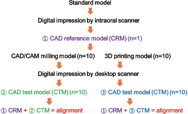
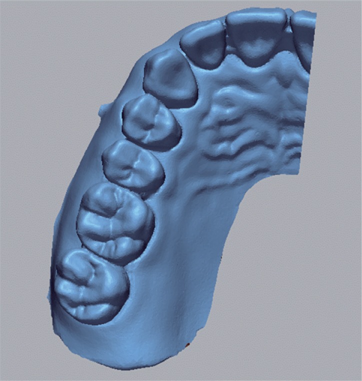
The reference plaster model was scanned using an intraoral scanner Trios (3Shape, Copenhagen, Denmark). The resulting scan data were designated as the CAD reference model (CRM). Trios is a confocal scanner with a real time rendering mode, which allows the practitioner to scan the target area while viewing it on the screen. We chose to use the intraoral scanner in this study to mimic an actual clinical setting. When scanning was completed, a reference STL file of the 3D shape of the plaster model was created (Fig. 2).
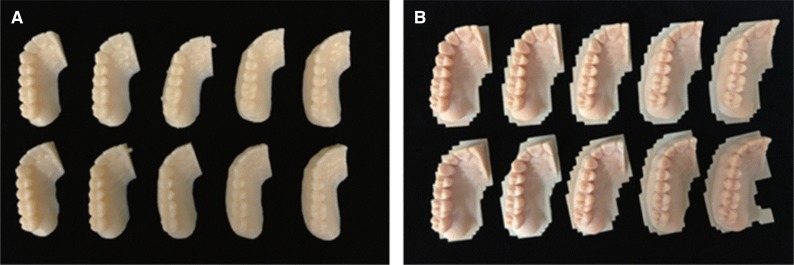
Based upon the reference STL file, a total of 10 milling models were manufactured using the milling equipment (ARUM 5X-200, Doowon, Korea). Polymethyl methacrylate (PMMA) blocks (Yamahachi PMMA Disk, Yamahachi Dental MFG, Aichi-Pref, Japan) were used as the material for the models. Burs with a maximum diameter of 2.5 mm and a minimum diameter of 1 mm were used. To maintain the same condition during milling, a single set of milling burs were used for a single block. Next, an additive manufacturing 3D printer (ZENITH, Dentis, Korea) was used to manufacture another 10 models, with the same condition, using a 16 µm layer. Models manufactured by milling were classified as group A, while those manufactured by 3D printing were group B. Each model was numbered in their respective group (i.e., A1–A10 and B1–B10) (Fig. 3).
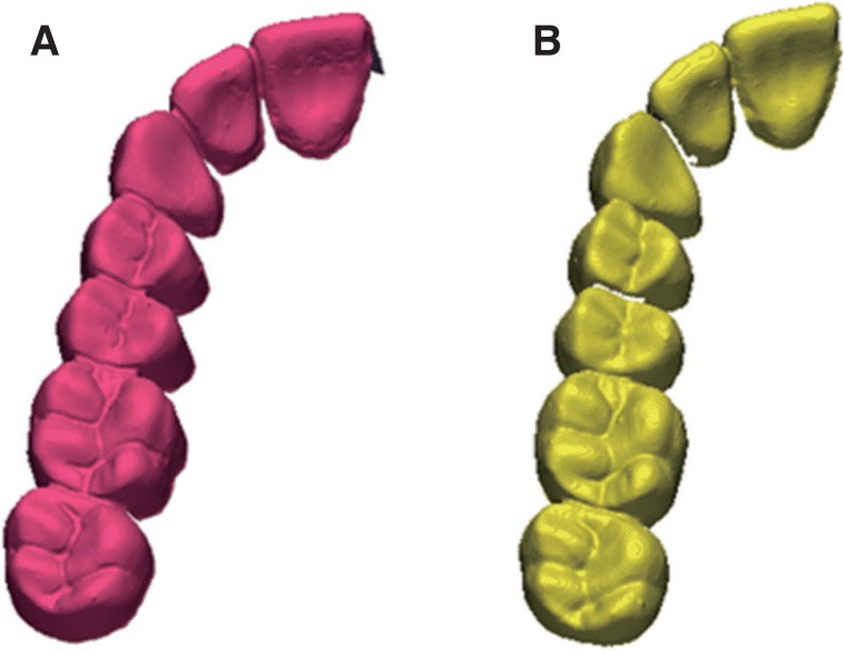
The 20 models manufactured by milling and 3D printing were scanned using a desktop scanner (Ceramill MAP 400, Amann Girrbach, Austria). Data of these scanned models were saved as test STL files (Fig. 4). A desktop scanner, rather than an intraoral scanner, was used in this case, since the former generated fewer errors during scanning, compared with those generated with the intraoral scanner, which correlated with the skill level and technique of the practitioner.
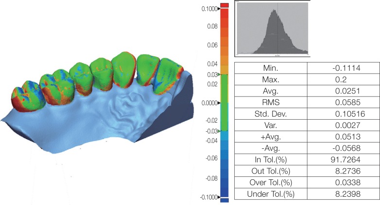
When the scan was completed, reference STL files were designated as a control group, while the test STL files were the test group. Each test STL file was superimposed on the reference STL file using specialized software (Geomagic Control X, 2017.0.3, 3D Systems, Cary, NC, USA). For superimposition, the test STL file was converted into point cloud data. Then, the CAD-reference-model (CRM), surface date, CAD-test-model (CTM), and the point cloud data, were initially aligned and subsequently rearranged to the best fit alignment. Finally, point cloud data was projected onto the surface of the CRM data. The sampling rate was set at 100%, with a maximum repetition index of 30. The distances between surface data and all points were converted to root mean square (RMS) values. The RMS is a general method to assess the mean value of errors, by directly comparing two data groups with an identical coordinate system. The accuracy of a corresponding data group can be calculated using a single scale. A higher calculated RMS value indicated a large error, i.e., the difference in the attributes between reference and measurement data. The RMS is typically used as a criterion to measure the similarity of two sets of N-dimensional vector sets after optimal superimposition. The equation used for the RMS calculation is as follows12:

Here, χ1,i is the data point of the CRM, and χ2,i is that of the CTM; and N is the number of all measurement points.
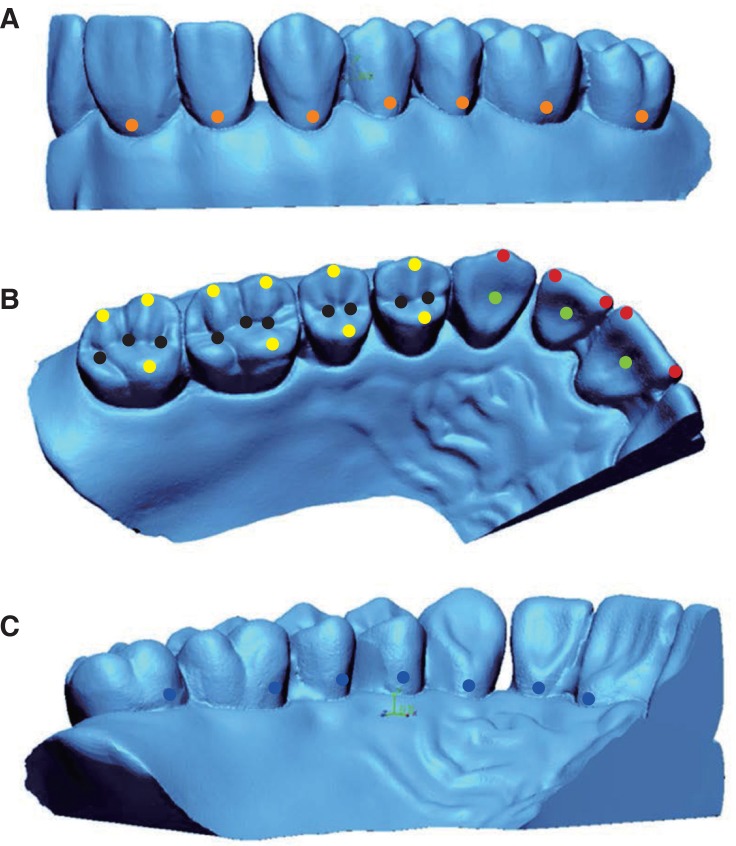
Unnecessary and inaccurate parts of the 3D shape data of all models were eliminated.13 The superimposition results were illustrated as a color difference map (Fig. 5). The maximum and minimum values of the color difference map were +100 µm and −100 µm, respectively. The effective range indicated in green was set from −30 µm to +30 µm. Although these values were not acceptable for prosthesis restoration, they were set to allow the easy comparison of the accuracy of the models produced using the milling and 3D printing methods. In addition, the two models were measured by using the fixed measuring points (e.g. cusp tip and fossa) in order to evaluate the clinical correlation of the discrepancies observed in between the models through RMS methods.14 The 42 assigned points were located as follows: incisal angle of the incisors (4 points), the tip of cusp of the canines (1 point), the cusp of the molars (10 points), lingual fossa of the incisors (3 points), fossa(pit) of the molars (10 points), undercut in the facial aspect (7 points), and undercut in the lingual aspect (7 points) (Fig. 6). For the location of these points, the divergences in the x-, y-, and z-axis to each reference and the test data were measured.15


A Shapiro-Wilk test was initially performed before the comparison of the mean values between the reference STL files and the test STL files of the scanned samples from each group. A Mann Whitney U test was conducted to determine significant difference between the groups. All statistical process and analysis were performed using IBM SPSS Statistics 23 (SPSS Inc., Chicago, IL, USA). The significance level was set at P <.05.
Go to :
RESULTS
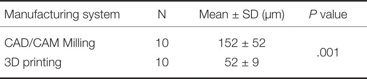
Table 1 and Table 2 outline the results of the accuracy assessment of the manufacturing methods, which was conducted using test software (Geomagic Control X, 2017.0.3, 3D Systems, Cary, NC, USA). Fig. 7 illustrates a graph of the RMS values of the 10 models in each group, while the results of the superimposition for 10 specimens in each group are outlined in Table 3 as the mean ± standard deviation.
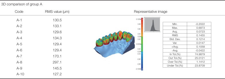
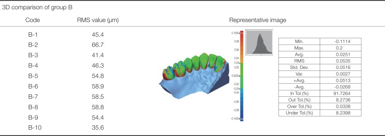
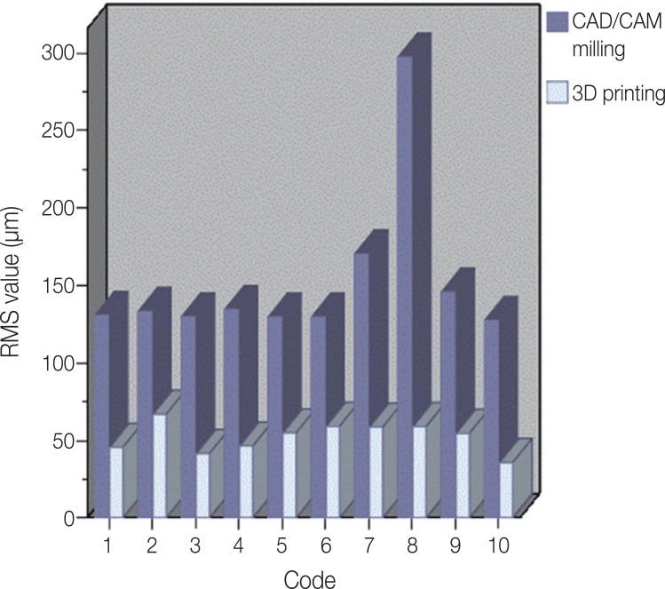
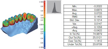
Table 1
Superposition of CRM and CTM of the model produced by CAD/CAM milling
| 3D comparison of group A | ||
|---|---|---|
| Code | RMS value (μm) | Representative image |
| A-1 | 130.5 |
|
| A-2 | 133.1 | |
| A-3 | 129.6 | |
| A-4 | 134.3 | |
| A-5 | 129.4 | |
| A-6 | 129.4 | |
| A-7 | 170.1 | |
| A-8 | 297.1 | |
| A-9 | 145.5 | |
| A-10 | 127.2 | |
![]()
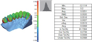
Table 2
Superposition of CRM and CTM of a model produced using 3D printing
| 3D comparison of group B | ||
|---|---|---|
| Code | RMS value (μm) | Representative image |
| B-1 | 45.4 |
|
| B-2 | 66.7 | |
| B-3 | 41.4 | |
| B-4 | 46.3 | |
| B-5 | 54.8 | |
| B-6 | 58.9 | |
| B-7 | 58.5 | |
| B-8 | 58.8 | |
| B-9 | 54.4 | |
| B-10 | 35.6 | |
![]()
The RMS values of the 10 models manufactured by the additive manufacturing 3D printer were lower than those manufactured by milling. Thus, in the measurement of the two kinds of models using the measuring points, same trend was observed except the pit of the molars (Table 4).
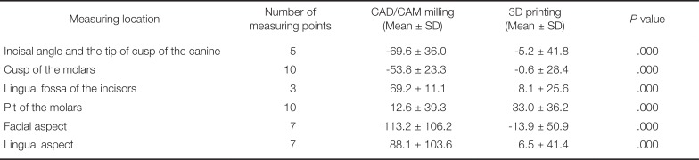
Table 4
Difference in mean distance to the point assigned in the anatomical locations of the teeth (unit: µm)
![]()
Go to :
DISCUSSION
The use of the milling method using the CAD/CAM system and the additive manufacturing 3D printing method to produce dental prostheses has been making steady progress, attracting a lot of interest in the dentistry field. When the CAD/CAM system was first introduced in dentistry, it was proposed as an alternative to solve various problems, including deformation, contraction, and expansion of the restorative prosthesis in the traditional casting method.16 Although the CAD/CAM system initially showed poor clinical suitability, its scanning, design software, and machining process have been systematically developed. Thus, it is currently at a level that is clinically acceptable.1718 Further, 3D printing was the beginning of the rapid prototyping system driven by stereolithography (SLA), which creates printed objects by polymerizing plastic liquids. The use of various materials, including wax, resin, and metal, have also been introduced. Currently, 3D printing and milling methods, which are being studied and applied in various fields, are already also widely used in dentistry. Comparative studies, to date, on the accuracy of milling and 3D printing to date, however, have mainly assessed the fit of dental prostheses. Given the development of scanners, the CAD/CAM system can now be used to manufacture prostheses without a model. However, in a study where the replica technique was used to assess 3D zirconia copings manufactured by milling, Moldovan19 concluded that the CAD/CAM process still needed improvements, in terms of standardization, reproducibility, and efficiency. Determining the fit of a prosthesis to a working model before its installation in the oral cavity of a patient is an important step in increasing the lifespan and stability of the prosthesis. Currently, there are two methods to manufacture working models using the CAD/CAM system as follows: milling and 3D printing. Therefore, in the current study, the accuracy of working models that were manufactured using milling and 3D printing methods, in reference to an STL file obtained by an intraoral scanner, was assessed.
In this study, given its higher precision, 5-axis machining equipment was used for milling, while 3D printing was conducted using a SLA 3D printer with a 16 µm layer. The RMS values of the working models manufactured by milling and 3D printing were 152 ± 52 µm and 52 ± 9 µm, respectively. This indicated that the 3D printing method was significantly more accurate than the milling method (P = .001). The data using the measuring points also showed statistical significance between the two manufacturing methods except that milling method presented smaller difference in the fossa compared to 3D printing method. This is thought to be the outcome of the crushed materials in the pit in 3D printing method whereas the deepest region (pit) of the fossa was manufactured by the milling bur in milling method. When the color difference maps of two models were analyzed using inspection software (Geomagic Control X, 2017.0.3, 3D Systems), compared to group B, group A showed red and blue areas in the occlusal surface, interdental space, and gingival sulcus. This indicated that the milling method was inferior to 3D printing, in terms of the reproducibility of these regions (i.e., the interdental space, gingival sulcus, and occlusal surface). Contrary to the past during when the milling software and milling devices for fabrication of dental models were not generalized, the use of an excellent 3D printer with fully developed technology is thought to be another reason.
A limitation of the current study is that the minimum thickness of the bur was 1 mm in the milling process, which limited the accurate reproduction of shapes that were smaller than 1 mm. However, a bur of less than 1 mm could not be used since PMMA resin was used as the milling material to produce the model. Since burs less than 1 mm (e.g., 0.6 mm) are easily heated, this would have caused the resin to be melted and adsorbed onto the bur, fracturing the bur in the process. In addition, data locations for the manufacture of a working model were selected on the CAM software before machining so that two models were arranged per single block. Although this arrangement was chosen to prevent the fracture of the bur and reduce the number of machining processes, it could have also affected the accuracy of the model.
The purpose of the current study was to analyze the accuracy of models manufactured via the milling method and 3D printing method using the CAD/CAM system. Further, we aimed to determine whether these processes can be used as working models to manufacture prostheses. The RMS values of working models manufactured by 3D printing were significantly lower than the values of those manufactured by milling. However, previous studies assessing the accuracy of digital models, obtained based on the dental elastic impression material,2021 reported RMS values of 5, 6, and 9 µm, for abutments produced from three different elastic impression materials, respectively, which did not corroborate with the current study. In addition, a clinically acceptable internal fit is 70 µm, which makes it difficult to produce a working model for prostheses manufacture. Furthermore, further study on temporary aspect (cost and time required for the production) is required for evaluation of the suitability of the two manufacturing methods for everyday use. However, given the improvements in the CAD/CAM system, materials and equipment with better specifications have been developed and introduced. Therefore, it is expected that the CAD/CAM system will soon be applicable to produce a working model for the manufacture of prostheses, which have a high degree of accuracy.
Go to :
CONCLUSION
The current study demonstrated that models manufactured by the 3D printing method were more accurate than those manufactured by the milling method, within the limitations of the study. However, currently, it is still challenging to apply the models manufactured by milling and 3D printing method as working models for dental prostheses manufacture.
Go to :
 XML Download