

 PDF
PDF ePub
ePub Citation
 Print
Print


INTRODUCTION
The orthodontic treatment of patients with bimaxillary protrusion occasionally involves significant retraction and intrusion of the anterior teeth for the achievement of an ideal occlusion and a more esthetic profile.12 However, some complications have been reported in previous studies, where severe maxillary incisor root resorption occasionally occurred after intensive anterior tooth retraction and intrusion.345678910 This can be attributed to various factors. For instance, certain anatomical structures may restrict tooth movement and cause root damage.11 In particular, the incisive canal, which is an anatomical structure in the maxillary anterior region that can be observed on three-dimensional (3D) computed tomography (CT) images, has recently gained attention because of its proximity to the maxillary central incisors.11121314
Compared with the use of a conventional mechanical approach, the use of a temporary anchorage device (TAD) has enabled orthodontists to achieve greater amounts of anterior tooth retraction.51516 However, inappropriate TAD use may aggravate the severity of root resorption. Therefore, to prevent severe root damage, clinicians should accurately evaluate the distance between the incisive canal and maxillary incisor roots and consider whether the position of the anatomical structures in this region will allow predictable anterior tooth movement before treatment initiation.
Till date, few studies have evaluated the maximum possible retraction and intrusion of the maxillary anterior teeth by using pretreatment 3D simulation of tooth movement with consideration of anatomical structures such as the alveolar bone and incisive canal. Here we describe a case of Class II malocclusion with bimaxillary protrusion, wherein the maximum limit of orthodontic maxillary incisor movement and anatomical structures were assessed on pretreatment cone-beam computed tomography (CBCT) images. 3D changes in the maxillary incisors and surrounding structures were evaluated over the long-term, and considerable retraction and intrusion of the incisors, which resulted in a marked improvement in the patient's facial profile and smile, were achieved without severe root resorption.
DIAGNOSIS AND ETIOLOGY
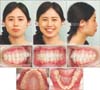
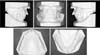
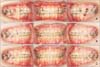
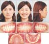
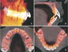
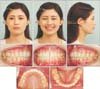
A 22-year-old woman presented with chief complaints of lip prominence, lip protrusion, and a gummy smile. Pretreatment facial photographs (Figure 1) showed a convex profile and protrusion of the upper and lower lips, both of which exceeded the E-lines (upper lip, +3.2 mm; lower lip, +5.7 mm). The molar relationship was Class II on the right side and Class I on the left. A mesial-distal difference was observed for the mandibular molars. The overbite and overjet were 4.0 mm and 8.0 mm, respectively (Figures 1 and 2).
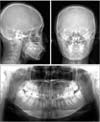
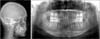
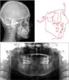
Lateral and anteroposterior cephalograms and an orthopantomogram were obtained before treatment initiation (Figure 3). Cephalometric analysis and tracing demonstrated a Class I skeletal relationship (a A point-nasion-B point [ANB] angle, 3.2π). Both the sella-nasion-A point (SNA, 82.4°) and Sella-nasion-B point (SNB, 79.2°) angles were normal, while the Frankfort mandibular plane (FMA) angle was small (20.5°; Table 1). The angle between the maxillary incisors and FH plane, the angle between the mandibular incisors and mandibular plane, and the interincisal angle were 128.3°, 102.9°, and 108.2°, respectively. The maxillary and mandibular incisors were labially inclined. Although the mandibular midline coincided with the facial midline on the facial photograph and anteroposterior cephalogram, a mesial-distal difference was observed for the mandibular molars on the lateral cephalogram.
On the basis of these findings, the patient was diagnosed with Class II Division 1 malocclusion with a protrusive profile and excessive gingival visibility.
TREATMENT OBJECTIVES
The treatment goals for this patient were as follows: to improve the facial profile and resolve the gummy smile, to establish Class I molar and canine relationships on both sides, and to achieve an ideal occlusion with the appropriate overbite and overjet.
TREATMENT ALTERNATIVES
Although we considered a treatment alternative without extraction of teeth other than the third molars, we eventually chose to extract four premolars and retract the anterior teeth to improve the protrusive profile. With regard to the right side of the mandible, we decided to extract the second premolar to obtain a Class I molar relationship via mesial molar movement. Accordingly, the maxillary left and right first premolars, mandibular right second premolar and left first premolar, and four third molars were extracted.
TREATMENT PROGRESS
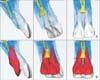
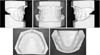
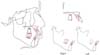
Pretreatment CBCT images were acquired for evaluation of the anatomical structures and determination of the position of the incisive canal and the positional relationships among the alveolar bone, incisive canal, and maxillary central incisors (Figure 4A). No obvious proximity was observed, and the incisive canal was behind the midpoints of the two central incisors. There was sufficient alveolar bone behind the maxillary central incisors that would facilitate the necessary amount of retraction. We simulated anterior retraction using 3-matic software (version 9.0; Materialise, Leuven, Belgium) and found that approximately 11.0 mm of central incisor retraction within the alveolar bone could be achieved (Figure 4B).
Subsequently, orthodontic treatment was initiated with the placement of a 0.016 × 0.022-inch nickel-titanium (Ni-Ti) archwire (L&H Titan wires; Tomy International, Tokyo, Japan) in preadjusted brackets with 0.018 × 0.025-inch slots (Dentsply-Sankin, Tokyo, Japan). Two orthodontic mini-screws (Dualtop; Jeil Medical Co., Seoul, Korea) were inserted between the maxillary second premolars and first molars to reinforce the anchorage for the canine and anterior tooth retraction. We initially began space closure via en-mass sliding mechanics using elastic power chains from the mini-screws to the long hooks placed between the lateral incisors and canines. Concurrent with anterior retraction, the mandibular right molars were moved mesially to obtain a Class I molar relationship. The patient's treatment progress is shown in Figure 5. We used only rectangular Ni-Ti wires as working archwires throughout the active treatment stages. We also added three adjustments to the working archwires in order to prevent canine distal tipping and incisor dumping and provide root lingual moment and intrusive force for the maxillary incisors (Figure 6). First, we incorporated gable bends between the canines and second premolars. Second, we added a compensating curve in the premolar and molars regions. Third, we fixed crimpable long hooks between the maxillary lateral incisors and canines. After 27 months of treatment with the edgewise appliance, circumferential-type retainers were placed in both the maxilla and mandible.
RESULTS
The patient's profile was improved and gummy smile eliminated after treatment. In addition, a Class I molar relationship and an ideal overjet and overbite were achieved (Figures 7 and 8). The patient was completely satisfied with the treatment outcomes. A lateral cephalogram and an orthopantomogram did not indicate severe root resorption (Figure 9). Cephalometric superimposition showed retraction of the maxillary and mandibular incisors along with intrusion, which resulted in the improvement in the facial profile (Figure 10). The mandibular right first molar had moved mesially through bodily movement. The pre- and post-treatment cephalometric measurements are shown in Table 1.
CBCT images acquired before and after treatment, with approval from the Institutional Ethical Committee of the Tokyo Medical and Dental University (approval number, 1254), were superimposed on the cranial base for evaluation of the root morphology and actual movements of the crowns and root apices (Figure 11); significant retraction and intrusion of the maxillary and mandibular incisors, without severe root resorption, were observed. The maxillary central incisors were intruded by 3.5 mm and distalized by 10.5 mm, whereas the mandibular central incisors were intruded by 0.5 mm and distalized by 4.8 mm. Although the lingual alveolar bone showed no changes, the quantity of buccal alveolar bone in the anterior region was markedly decreased because of the anterior tooth retraction in both jaws. Consequently, the facial esthetics were improved with a decrease in the upper and lower lip protrusion.
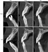
The post-treatment stability of the achieved occlusion was evaluated 2 years after the completion of active orthodontic treatment, and the occlusion was found to be acceptable (Figures 12 and 13). Throughout the orthodontic treatment course, including retraction and intrusion of the anterior teeth, the length of the upper central incisors decreased by 0.9 mm on the right side (pretreatment, 23.1 mm; post-treatment and post-retention, 22.2 mm) and 1.1 mm on the left side (pretreatment, 23.3 mm; post-treatment and post-retention, 22.2 mm; Figure 14).
DISCUSSION
We simulated anterior tooth retraction and evaluated the position of the anatomical structures using CBCT before treatment initiation for a patient with Class II malocclusion and bimaxillary protrusion and achieved significant tooth retraction and intrusion without severe root resorption. The patient's facial profile considerably improved and her gummy smile was eliminated after treatment.
Determination of the position of the maxillary incisors is key for orthodontic diagnosis and treatment planning.12 Significant anterior tooth retraction and intrusion are occasionally necessary for an improvement in the facial profile and smile in patients with bimaxillary protrusion. Nonetheless, orthodontically induced inflammatory root resorption most frequently affects the maxillary central incisors and is reportedly associated with risk factors such as root morphology, root proximity to the cortical bone, anatomical structures, and the amount of apical root movement.3456
The incisive canal is an anatomical structure located on the median plane of the palatine process of the maxilla, posterior to the roots of the central incisor, and is surrounded by thick cortical bone. The incisive canal contains the nasopalatine vessels and nerves, branches of the maxillary division of the trigeminal nerve, and the maxillary artery.11121314 The proximity of the maxillary incisor roots to the incisive canal and approximation or invasion of the incisive canal by the tooth roots after anterior tooth retraction has not been evaluated in detail, probably because the incisive canal is a midsagittal structure positioned between the roots, with a morphology and dimension that are not clearly defined on conventional two-dimensional (2D) images. However, the availability of 3DCT has allowed observation of the incisive canal as an anatomical structure that may be associated with orthodontically induced inflammatory root resorption in the maxillary central incisors during maximum retraction.11121314 Variations in the morphology of the incisive canal have frequently been reported in 3DCT studies; these include lateral deviation, widening or cystic changes, and furcation, among others.11 Therefore, evaluation of the “safe zone” (i.e., the area of safe tooth movement within the alveolar bone) using pretreatment 3DCT images may be very important to ensure minimal apical root damage.
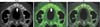
Accordingly, in the present case, we performed orthodontic treatment after evaluation of the anatomical structures on CBCT images in order to avoid severe root damage as far as possible, considering an extensive amount of retraction and intrusion were required to resolve the patient's chief complaints. Specifically, we evaluated the positional relationship between the incisors and incisive canal and simulated the maximum amount of maxillary central incisor retraction before treatment (Figure 4). We found that the central incisors could be safely retracted without contacting the incisive canal by approximately 11.0 mm within the alveolar bone. On post-treatment CBCT images, there was no obvious cortical bone on the palatal side of the maxillary incisors (Figure 14). However, on follow-up images obtained 2 years later, a layer of cortical bone was confirmed. We speculated that there was thin bone that could not be confirmed on CBCT performed immediately after treatment, and that bone remodeling may have occurred on the palatal side during the retention phase. Moreover, when superimposed post-treatment and post-retention CBCT images were closely studies (Figure 15), it was observed that the cortical bone had clearly regenerated around the incisive canal after 2 years, although the left central incisor now contacted the incisive canal. No other changes were observed in the buccal and lingual cortical bone during the post-retention period. Furthermore, the maxillary left central and lateral incisors had moved to the center of the alveolar bone and were covered with cortical bone. Such observations would have been difficult on conventional 2D images.
Retraction and intrusion of the maxillary incisors is more marked when TAD is used than when the conventional technique is used.1516 However, the basic morphological structure and response to tooth movement may vary among patients, and evidence of changes in or adaptation of the anatomical structures after the use of advanced biomechanical techniques is still lacking. Therefore, long-term follow-up studies with 3D evaluations are required.
Although a significant amount of retraction and intrusion of the maxillary incisors would increase the risk of apical root resorption,345 we were able to achieve a considerable amount of apical movement without observing severe apical root resorption on CBCT images in our case. In a previous study, root resorption of approximately 2.5 to 2.8 mm occurred after maximum maxillary anterior retraction using TAD.5 On the other hand, the length of the maxillary central incisors decreased by an average of 1.0 mm in our case (right, 0.9 mm; left, 1.1 mm).
We agree that the prevention of root resorption entirely by 3DCT-based diagnosis and treatment simulation is impossible, because other factors such as the magnitude of orthodontic force and treatment duration can induce root damage.3456 Nevertheless, we believe that a 3DCT-based diagnostic work-up and software-based simulation of tooth movement can aid in decreasing the severity of root resorption. These conclusions are, however, hypothetical, and further studies evaluating the effectiveness of 3DCT-based diagnosis and treatment simulation are awaited.
CONCLUSION
In conclusion, we used 3DCT-based diagnosis and software-based simulation of tooth movement before treatment for a patient with bimaxillary protrusion and achieved a considerable amount of maxillary incisor retraction and intrusion, which resulted in an improvement in the facial profile and smile, without severe root resorption. The findings from this case suggest that customized 3D evaluation of the dimensions and location of the incisive canal is advantageous for preventing potential complications in patients requiring maximum anterior tooth retraction.


 XML Download