Journal List > J Korean Soc Radiol > v.78(4) > 1095528

Yun, Kang, Ahn, Lee, Lee, Oh, and Kang: A Comprehensive Review of Shoulder CT Morphometry: What Surgeons Wants to Know

Abstract

A variety of surgical techniques have been employed for shoulder problems, i.e., arthroplasty, arthroscopy, and fracture fixation, etc. A thorough understanding and knowledge of the normal anatomy, physiology, biomechanics, and pathomechanics of the glenohumeral joint can help facilitate a successful pre-operative evaluation of the shoulder. The authors reviewed practical measurement methods of a shoulder computed tomography (CT) with three-dimensional volume-rendered images, from the orthopedic surgeon's viewpoint, to aid radiologists make structured reports. It is important that the radiologist be familiar with the normal and abnormal imaging appearances of the shoulder CT before and after the surgical procedures.

INTRODUCTION

Shoulder computed tomography (CT) scans are commonly encountered by radiologists in routine preoperative and emergency settings. As the demand of CT analysis of shoulder joint increases, understanding of the shoulder CT morphometry is imperative for high quality patient care. Whether the treatment involves surgical procedure or not, the assessment of a shoulder CT plays an essential role in the treatment planning as well as triage.
In the clinical cases requiring surgical intervention, the orthopedic surgeons depend on the radiologic reports to determine the method and extent of operation, and to predict the prognosis of the surgery. Therefore, it is critical for radiologists to be familiar with surgeons needs and provide accurate image interpretation to ensure proper management of the patients.
In the first part of this article, we reviewed the osseous anatomy of the shoulder to help understand the shoulder joint morphometry. Then, we described the glenoid morphology and version, humeral head retroversion for shoulder arthroplasty. In addition, glenohumeral instability and humeral translation distance will be discussed for preoperative arthroscopic evaluation. Fractures of the shoulder region and clinically relevant measurement criteria that may affect the outcomes of operation were also reviewed.

NORMAL ANATOMY OF THE SHOULDER

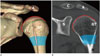
The proximal humerus, scapula, and clavicle compose the bony part of the shoulder. The proximal humerus is comprised of four parts: the greater tuberosity, lesser tuberosity, humeral head, and surgical neck (Fig. 1). The greater tuberosity is located lateral to the head of the humerus, which is the insertion site of the supraspinatus, infraspinatus, and teres minor tendons. The lesser tuberosity is a smaller, anteromedially located tubercle, where the subscapularis tendon attaches. The humeral head articulates with the glenoid fossa forming glenohumeral joint. The articular surface is normally angled between 30° to 55° relative to the axis of the humeral shaft (1).
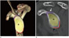
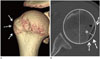
The anatomical neck of the humerus is the attachment site for the capsular ligaments of the joint except the upper inferior-medial area (2). Fracture of the anatomical neck of the humerus is associated with an increased risk of avascular necrosis. The surgical neck of the humerus lies below the greater and lesser tuberosities. This is the most common fracture site as well as developmentally a primary physis of the proximal humerus (3). The glenoid fossa of scapula is a pear-shaped articular surface of the lateral scapula, which articulates with the head of the humerus (Fig. 2). It is normally tilted posteriorly, upward facing with respect to the plane of scapula, although it is variable among individuals. The superior and inferior glenoid tubercles are two small bony eminences in the glenoid cavity, where the long heads of the biceps and triceps brachii muscles attach.
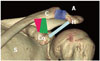
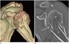
The clavicle is an S-shaped bone, which forms the sternoclavicular joint by articulating with the manubrium of the sternum. The clavicle also articulates with the scapula forming the acromioclavicular (AC) joint, the coracoid with the medial conoid, and lateral trapezoid ligaments form the coracoclavicular (CC) ligament (Fig. 3). The AC joint functions as a suspensory support for the upper extremity and a force transmitter from the appendicular to axial skeletons. While the AC ligament functions as a primary restraint for horizontal stability to the AC joint in the posterior translation, CC ligament serves as a vertical stabilizer (4).
A gamut of preoperative radiologic evaluations should be made prior to various clinical conditions, including arthroplasty, arthroscopy, and trauma settings to communicate with the surgeons for better clinical outcomes.

PREOPERATIVE EVALUATION FOR ARTHROPLASTY

Glenoid Version

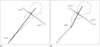
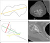
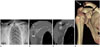
The preoperative evaluation of the glenoid version is essential for proper anatomical reconstruction in shoulder arthroplasty (567), because the proper positioning of the implant to maintain balance in the shoulder joint, is imperative for postoperative clinical success and long term stability (89). Glenoid version as defined by Friedman et al. (7) is the angle between glenoid articular surface relative to the scapula axis (Fig. 4A). First, the line G is drawn connecting the anterior and posterior margins of the glenoid. Then, the line S, starting from the medial end of the scapula passing through the center of the glenoid is drawn. The line S′ is defined as the line perpendicular to the line S. The glenoid version is the angle between line G and line S′, 4 slices below the level of the coracoid on the 2.5 mm thickness axial two-dimensional (2D) CT image. Based on the fact that the glenoid version as measured using the Friedman method can be greatly influenced by the shape of the scapula, Matsumura et al. (10) suggested a method using the scapula vault axis (Fig. 4B). The line G is the same as in the Friedman method, but line S is defined as the line connecting the tip of the scapular vault to the center of the glenoid. The vault method showed larger glenoid retroversion in both normal individuals and patients with osteoarthritis than the conventional Friedman method. Because the vault method can eliminate the scapula body angulation, it could be used as an alternative method for measuring glenoid version (10).
The surgical strategies can be modified based on the degree of the glenoid retroversion, which is known to be associated with poor surgical outcome. In the case of retroversion, anterior glenoid reaming or bone grafting is required to restore normal joint biomechanics (611).

Glenoid Morphology

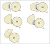
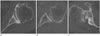
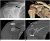
The bony erosion tends to occur at the posterior aspect of the bony glenoid as the degree of primary glenohumeral osteoarthritis increases, which might lead to glenoid retroversion and humeral subluxation (12). The 3 classifications defined by Walch (12), are based on the CT evaluation (Fig. 5). Type A morphology is defined as a central bony erosion sub-classified into A1 (minor erosion) (Fig. 6A) or A2 (major erosion). In type B, the humeral head is subluxed posteriorly with either posterior joint space narrowing, subchondral sclerosis, osteophyte (Figs. 5, 6B) or posterior rim erosions and glenoid retroversion > 2° (Fig. 5). Type C morphology describes glenoid retroversion of > 25°, regardless of the erosion (Figs. 5, 6C).

Humeral Head Retroversion

Humeral head retroversion is one of the fundamental stabilizing mechanisms of the glenohumeral joint. The degree of retroversion affects the mobility and stability of the glenohumeral joint (131415). The retroversion angle is defined as the angular difference between the orientation of the proximal humeral articular surface and the various reference axes, including the transepicondylar axis (1617), trochlear tangent axis (1819), bicipital groove (2021), and lesser tuberosity (8). The transepicondylar axis (Fig. 7A, B) is frequently used as the distal reference because the epicondyles are palpable structures allowing surgeons to assess the epicondylar line during surgery. Boileau et al. (13) proposed the following method using CT scans. First, the line A′ is drawn in the center of the humeral head at the level of margin of the cartilage, perpendicular to the diameter of the humeral head (line A). Then, the transepicondylar axis, line B is drawn connecting the most prominent medial and lateral epicondyles. The humeral head axis is defined as the angle between lines A′ and B (13) (Fig. 7C, D). The retroversion angle of the humeral head by transepicondylar axis is variable, ranging from 10° to 40° (13). It is one of the most widely used methods in the 2D CT (22). On the other hand, several reports have demonstrated that the three-dimensional (3D) volume-rendering CT technique has higher inter-observer reliability for the measurement of humeral retroversion (23). Further studies are warranted to establish the accurate reference standard for humeral retroversion.

PREOPERATIVE EVALUATION FOR ARTHROSCOPY

Glenohumeral Instability: Bony Bankart and Hill-Sachs Lesions

Several risk factors have been found to predict the recurrence of glenohumeral instability following arthroscopic surgery including bone loss at glenoid and humeral heads, patient age, and shoulder hyperlaxity (242526). Among them, CT images serve as the reference standard for identifying and quantifying bone loss at the glenoid and humeral heads. Furthermore, CT images help in the decision of the treatment plan and predict prognosis after the surgery (26272829).
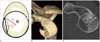
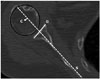
The Bankart lesion is defined as an anterior tear of glenoid labrum from the glenoid rim, sometimes accompanied by fracture of the glenoid (bony Bankart) that is associated with anterior dislocation of the shoulder. Although there have been some reports of evaluating glenoid bone loss arthroscopically, those methods can easily overestimate glenoid bone loss (30). 3D CT imaging is the most accurate and important study for evaluating glenoid morphology (31). Preoperative 3D CT images provide detailed structural information about the glenoid shape, and bone loss with quantification. Although there are several methods for the assessment of glenoid bone loss on 2D or 3D CT images published till date, there has been no consensus on the best method for the glenoid bone loss quantification (2932). Bois et al. (33) compared various methods of assessing glenoid bone loss and concluded that the most accurate required bilateral imaging of the shoulder. As one of the methods using unilateral shoulder imaging, Nofsinger et al. (34) suggested the following method for measuring bony Bankart lesion; first, a circle that perfectly fits the glenoid fossa is drawn on the lower glenoid. The line from the center of the humeral head to the margin of the bone loss and the radius of the best fit circle are compared (Fig. 8). This measurement uses radius to estimate the area lost on axial CT images. However, it is important to note that the correlation between area and radius does not follow a linear 1:1 ratio. For instance, when the percentage of radius lost is 20%, the area of bone lost is only 5%. When 60% of radius is lost, 25% of the bone area is lost. Any size of the bony Bankart lesion is associated with instability which positively correlates with the size of the defect (28). The Nofsinger approach could be used as a default method, but there are different preferences for measuring glenoid bone loss.
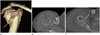
The Hill-Sachs lesion is an impression fracture of the humeral head due to impaction of the posterolateral aspect of the anteriorly dislocated humeral head with the anterior rim of the glenoid. The lesion can be evaluated within 14–15 mm from the top of humeral head, which should normally be circular. Because the ‘normal groove’ of the humeral head is also located at posterolateral humeral head, it may lead to overestimation of the extent of the Hill-Sachs lesion. However, the ‘normal groove’ is usually located more inferiorly, 20–39 mm from the top of the humeral head, which helps differentiate between the two lesions (3536). The Hill-Sachs lesion is measured as the largest humeral head defect on the axial image. The width of the Hill-Sachs lesion is defined as the distance between the anterior and posterior defects. The depth of this lesion is measured from the deepest defect to the circle of humeral head (3537) (Fig. 9). A number of studies have demonstrated that the size of the Hill-Sachs lesion correlates with engagement into the glenoid, predisposing to glenohumeral instability (38). Small defects affecting humeral head affecting less than 20% of the humeral head circumference are usually clinically insignificant, whereas large defects affecting more than 40% are clinically significant (3940). Therefore, the threshold for treatment has been estimated at between 20% to 40% of humeral head involvement.

Measurement of the Humeral Translation Distance

The humeral head is anatomically located in the center of the glenoid by the balance of various shoulder structures including the labrum, joint capsule, and rotator cuff muscles. In patients with clinical shoulder instability, the humeral translation distance is increased with more extensive tears of the posterior labrum (414243). The scapula line is drawn tangential to anterior surface of the scapula bisecting the line connecting the anterior and posterior osseous glenoid (Fig. 10). Thus, the humeral translation distance is defined as the distance between the scapula line and the center of the humeral head (414243).

MEASUREMENTS IN TRAUMATIC SETTINGS

Review of Neer Classification and CT Imaging

The proximal humeral head fractures are one of the most common skeletal fractures accounting for 5% of all extremity fractures (44). Fractures of the proximal humerus are classified by the method Neer (45) developed based on the involvement of 4 parts: the humeral head, lesser tuberosity, greater tuberosity, and humeral shaft. A fracture part is considered separate if it is displaced at least 1 cm or angled 45° respectively. Fractures are considered as one-part fracture unless they meet the criteria for displacement or angulation regardless of the number and location of the fracture lines. In two-part fractures, one of the four parts is separate (Fig. 11). Either the greater tuberosity or lesser tuberosity with humeral shaft could be displaced from the articular surface in three-part fractures (Fig. 12). Four-part fractures have four separate parts without glenoid articulation or soft tissue contact.
One-part fractures account for 85% of proximal humeral fractures generally treated conservatively (45). The management of fractures involving more than two parts is controversial, but new techniques have increased the overall range of fractures that benefit from operations (46). However, the poor intra-observer reproducibility and inter-observer reliability results from recent studies question the reliability of the Neer classifications (4748). Furthermore, few important elements from the surgeons point of view such as articular split or concomitant glenohumeral dislocation are not included in Neer classifications, which should be evaluated from quality radiological reports (3). However, the Neer classifications are more reliable and better evaluated with CT images than plain radiographs alone (4950).
The factors reported to be associated with increased risk of complicated proximal humeral fracture, and humeral head ischemia are the number of tuberosity displacements, glenohumeral joint dislocation, three or more fragments, and angular displacement of the head (51). Fractures extending to the articular surface are difficult to fix and the result worsens as the patient ages (52). Additionally, in the case of joint dislocation with fracture, there is an increased risk for joint instability and neurovascular injury (46). Therefore, it is important for the radiologists to include not only the measurement of angulation and displacement, but also the presence of articular split or glenohumeral joint dislocation.

AC Joint Dislocation

AC joint dislocations encompass up to 9% of all AC injuries (53). Radiologic classification of AC joint dislocations were made by Williams et al. (54) in 1989, which classified six different grades of AC joint dislocations. Type I injury is defined as a minor sprain of the AC ligaments (54). Type II injury represents a complete rupture of the AC ligament with a CC ligament sprain. Type III injury results from the rupture of both AC and CC ligaments (Fig. 13). Type IV, V, and VI injuries have ligamentous ruptures in common with that of Type III, but may involve additional deltoid and trapezius muscle injuries. They are classified based on the direction of the clavicular displacement. If the clavicle is posteriorly displaced into the trapezius muscle, it is defined as Type IV. The axillary view or CT images are of paramount importance when evaluating injuries involving the posterior displacement of the clavicle (55). In Type V injuries, the clavicle could be superiorly displaced from 100% to 300% (Fig. 14). Type VI describes injuries with inferiorly displaced clavicle posterior to the coracoid process and conjoint tendon. This classification serves as the basis for the decision-making process in the management of AC joint injuries. Management of the Type I and II injuries is usually conservative. Unstable injuries including Types IV, V, and VI require early surgical repair. The management of Type III, which is a turning point between stable and unstable injuries, is controversial and includes both surgical and nonsurgical treatment techniques (46).

CONCLUSION

CT is an important and frequently used imaging tool for evaluation of the osseous anatomy of the shoulder joint in various clinical settings. The elements necessary for the surgeons to assess the morphology of the shoulder joint could determine the severity of the injury and necessity of surgery. The accurate CT-based assessment of the shoulder joint ensures that surgeons receive all the necessary information, thereby promoting optimal clinical outcomes and prognoses.

Figures and Tables

Fig. 1

The normal anatomy of the shoulder joint of a 20-year-old female. Three-dimensional volume-rendered (A), coronal-reformatted computed tomography images (B). The proximal humerus comprises the humeral head (shown in red line on online figure), anatomical neck (shown in green dotted line on online figure), surgical neck (shaded area), greater tubercle, lesser tubercle, and the bicipital groove (shown in pink line on online figure, between GT and LT).

A = acromion, C = clavicle, Co = coracoid process, G = glenoid, GT = greater tubercle, H = humerus, LT = lesser tubercle, S = scapula
jksr-78-265-g001
Fig. 2

The normal anatomy of glenoid in a 20-year-old female. Three-dimensional volume-rendered (A), sagittal-reformatted images (B). The glenoid is composed of the glenoid neck and fossa. The superior (shown in purple line on online figure, white arrows) and inferior (shown in orange line on online figure, black arrows) glenoid tubercles are two small tubercles located above and below the glenoid cavity on the scapula.

A = acromion, C = clavicle, Co = coracoid process, G = glenoid, S′ = supraspinous fossa
jksr-78-265-g002
Fig. 3

The normal anatomy of shoulder joint of a 20-year-old female. Three-dimensional volume-rendered image demonstrates acromioclavicular ligament (shown in purple on online figure), coracoclavicular ligament comprised of conoid (shown in pink on online figure) and trapezoid (shown in green on online figure) components and the coracoacromial ligament (shown in light blue on online figure).

A = acromion, C = clavicle, Co = coracoid process, H = humerus, S = scapula
jksr-78-265-g003
Fig. 4

Glenoid version measurement by Friedman and Matsumura method.

A. The glenoid version is measured as the angle (α) between line G and line S′ on axial image using the Friedman method.
B. The glenoid version is measured as the angle (β) between line G and line S′ on the axial image using the Matsumura method. The Matsumura vault method showed larger glenoid retroversion (20°) than the Friedman glenoid version (13°) method.
Line G = Line connecting the anterior and posterior margin of the glenoid, Line S = Line connecting the tip of the scapular vault to the center of the glenoid, Line S′ = Line perpendicular to line S
jksr-78-265-g004
Fig. 5

Walch classificiation of glenoid wear. On the left, centered humeral head with minor (Walch type A1) or major (Walch type A2) central erosion is demonstrated. In the middle, the humeral head is posteriorly subluxed with narrowing of the posterior joint space, osteophytes, sclerosis (Walch type B1) and posterior rim erosion with retroverted glenoid (Walch type B2). On the right, Walch type C morphology is demonstrated as a glenoid retroversion more than 25 degrees regardless of the erosion.

H = humeral head
jksr-78-265-g005
Fig. 6

CT images of glenoid wear by walch classification.

A. Axial CT image of the left shoulder of a 50-year-old female showing central erosion without retroverted glenoid, consistent with Walch type A1 morphology.
B. Axial CT image of the shoulder of a 61-year-old male showing narrowing of the posterior joint space, posterior subluxation of humeral head and subchondral sclerosis without retroverted glenoid classified as Walch type B1 morphology.
C. Axial CT image of the shoulder of a 71-year-old female showing marked posterior glenoid wear with fragmentation of the posterior glenoid rim with retroverted glenoid, compatible with Walch type C morphology.
CT = computed tomography
jksr-78-265-g006
Fig. 7

Measurement of Humeral head retroversion.

A, B. Illustration (A), CT axial image (B) a 67-year-old female shows transepiphyseal line (line B) between the most prominent medial and lateral epicondyles.
C. The humeral head retroversion is defined as the angular difference between the orientation of the proximal humeral head (line A′) and the axis of the elbow at the level of distal humerus (line B).
D. Axial shoulder computed tomography image demonstrates the transepiphyseal line and humeral head retroversion.
Line A = a line passing through the center of the head of the humerus, Line A′ = a line perpendicular to line A, Line B = transepicondylar axis
jksr-78-265-g007
Fig. 8

Measurement of the bony Bankart lesion.

A. A best fit circle (black circle) is drawn covering the curve of inferior portion of the glenoid (grey line) R2 is the line from the center of the glenoid center to the margin of the bony Bankart lesion.
B, C. Volume-rendered (B), sagittal computed tomography (C) images show a bony Bankart lesion at the antero-inferior glenoid.
G = glenoid
jksr-78-265-g008
Fig. 9

Measurement of the Hill-Sachs lesion. Volume-rendered (A), axial shoulder computed tomography (B) images show a Hill-Sachs lesion (arrows). W (black line) is the distance between anterior and posterior margin of the defect, while D (white line) is the distance between the floor of the defect and the imaginary contour of the humeral head. The relative percentage to the diameter (white dotted line) of the humeral head was also calculated.

D = depth, W = width
jksr-78-265-g009
Fig. 10

Quantifying the humeral position relative to glenoid fossa on axial shoulder computed tomography image in a 76-year-old female. The humeral translation distance is defined as the distance from the center of the humeral head to the scapular line (line S, at mid glenoid level). Line G = line connecting anterior and posterior end of osseous glenoid, Line S = axis of scapula, line from anterior surface of the scapular body to the midpoint of line G.

jksr-78-265-g010
Fig. 11

Comminuted humeral surgical neck fracture in a 50-year-old female after a fall. Volume-rendered (A), shoulder computed tomography (B) images show a significant angulation(≥ 45′) (arrows) with displacement of the surgical neck, suggesting a two-part fracture.

H = humerus, S = scapula
jksr-78-265-g011
Fig. 12

Comminuted right humeral fracture in a 40-year-old female involved in a traffic accident. Volume-rendered (A), axial shoulder computed tomography (B, C) images show a significant displacement (≥ 1 cm) of greater tuberosity (black arrows) and impaction at surgical neck (white arrows), suggesting a three-part fracture.

jksr-78-265-g012
Fig. 13

Plain radiograph, CT images of a 53-year-old male after a fall. Plain radiograph demonstrates widening of the AC joint space (white arrow in A), and CC interval (black arrow in A). There was a 50% (between 25–100%) increase in the CC interval, the lesion was classified as Rockwood Type III. CT images also revealed widening of the AC (white arrow in B, D) and CC spaces (black arrow in C, D).

jksr-78-265-g013
Fig. 14

Plain radiograph, CT images of a 21-year-old male after a fall. The plain radiograph demonstrates the widening of AC joint space (white arrow in A), CC interval (black arrow in A). Because the CC joint space was twice wider than the normal left, the lesion was classified as Rockwood Type V. CT images also revealed separation of the AC (white arrow in B, D) and CC spaces (black arrow in B, C).

AC = acromioclavicular, CC = coracoclavicular, CT = computed tomography
jksr-78-265-g014

References

1. Pearl ML. Proximal humeral anatomy in shoulder arthroplasty: implications for prosthetic design and surgical technique. J Shoulder Elbow Surg. 2005; 14:1 Suppl S. 99S–104S.
crossref
2. Whiston TB. Fractures of the surgical neck of the humerus. J Bone Joint Surg Br. 1954; 36-B:423–427.
crossref
3. Sandstrom CK, Kennedy SA, Gross JA. Acute shoulder trauma: what the surgeon wants to know. Radiographics. 2015; 35:475–492.
crossref
4. Fukuda K, Craig EV, An KN, Cofield RH, Chao EY. Biomechanical study of the ligamentous system of the acromioclavicular joint. J Bone Joint Surg Am. 1986; 68:434–440.
crossref
5. Hoenecke HR Jr, Hermida JC, Flores-Hernandez C, D'Lima DD. Accuracy of CT-based measurements of glenoid version for total shoulder arthroplasty. J Shoulder Elbow Surg. 2010; 19:166–171.
crossref
6. Shapiro TA, McGarry MH, Gupta R, Lee YS, Lee TQ. Biomechanical effects of glenoid retroversion in total shoulder arthroplasty. J Shoulder Elbow Surg. 2007; 16:3 Suppl. S90–S95.
crossref
7. Friedman RJ, Hawthorne KB, Genez BM. The use of computerized tomography in the measurement of glenoid version. J Bone Joint Surg Am. 1992; 74:1032–1037.
crossref
8. Iannotti JP, Norris TR. Influence of preoperative factors on outcome of shoulder arthroplasty for glenohumeral osteoarthritis. J Bone Joint Surg Am. 2003; 85-A:251–258.
crossref
9. Inui H, Sugamoto K, Miyamoto T, Machida A, Hashimoto J, Nobuhara K. Evaluation of three-dimensional glenoid structure using MRI. J Anat. 2001; 199(Pt 3):323–328.
crossref
10. Matsumura N, Ogawa K, Ikegami H, Collin P, Walch G, Toyama Y. Computed tomography measurement of glenoid vault version as an alternative measuring method for glenoid version. J Orthop Surg Res. 2014; 9:17.
crossref
11. Farron A, Terrier A, Büchler P. Risks of loosening of a prosthetic glenoid implanted in retroversion. J Shoulder Elbow Surg. 2006; 15:521–526.
crossref
12. Walch G, Badet R, Boulahia A, Khoury A. Morphologic study of the glenoid in primary glenohumeral osteoarthritis. J Arthroplasty. 1999; 14:756–760.
crossref
13. Boileau P, Bicknell RT, Mazzoleni N, Walch G, Urien JP. CT scan method accurately assesses humeral head retroversion. Clin Orthop Relat Res. 2008; 466:661–669.
crossref
14. Kronberg M, Broström LA. Humeral head retroversion in patients with unstable humeroscapular joints. Clin Orthop Relat Res. 1990; (260):207–211.
crossref
15. Boileau P, Walch G, Liotard JP. [Radio-cinematographic study of active elevation of the prosthetic shoulder]. Rev Chir Orthop Reparatrice Appar Mot. 1992; 78:355–364.
16. Robertson DD, Yuan J, Bigliani LU, Flatow EL, Yamaguchi K. Three-dimensional analysis of the proximal part of the humerus: relevance to arthroplasty. J Bone Joint Surg Am. 2000; 82-A:1594–1602.
crossref
17. Hempfing A, Leunig M, Ballmer FT, Hertel R. Surgical landmarks to determine humeral head retrotorsion for hemiarthroplasty in fractures. J Shoulder Elbow Surg. 2001; 10:460–463.
crossref
18. Kummer FJ, Perkins R, Zuckerman JD. The use of the bicipital groove for alignment of the humeral stem in shoulder arthroplasty. J Shoulder Elbow Surg. 1998; 7:144–146.
crossref
19. Hertel R, Knothe U, Ballmer FT. Geometry of the proximal humerus and implications for prosthetic design. J Shoulder Elbow Surg. 2002; 11:331–338.
crossref
20. McPherson EJ, Friedman RJ, An YH, Chokesi R, Dooley RL. Anthropometric study of normal glenohumeral relationships. J Shoulder Elbow Surg. 1997; 6:105–112.
crossref
21. Krahl VE. The phylogeny and ontogeny of humeral torsion. Am J Phys Anthropol. 1976; 45(3 pt. 2):595–599.
crossref
22. Saka M, Yamauchi H, Yoshioka T, Hamada H, Gamada K. Conventional humeral retroversion measurements using computed tomography slices or ultrasound images are not correlated with the 3-dimensional humeral retroversion angle. Orthop J Sports Med. 2015; 3:2325967115573701.
crossref
23. Saka M, Yamauchi H, Hoshi K, Yoshioka T, Hamada H, Gamada K. Reliability and validity in measurement of true humeral retroversion by a three-dimensional cylinder fitting method. J Shoulder Elbow Surg. 2015; 24:809–813.
crossref
24. Boileau P, Villalba M, Héry JY, Balg F, Ahrens P, Neyton L. Risk factors for recurrence of shoulder instability after arthroscopic Bankart repair. J Bone Joint Surg Am. 2006; 88:1755–1763.
crossref
25. Taylor DC, Arciero RA. Pathologic changes associated with shoulder dislocations. Arthroscopic and physical examination findings in first-time, traumatic anterior dislocations. Am J Sports Med. 1997; 25:306–331.
26. Stevens KJ, Preston BJ, Wallace WA, Kerslake RW. CT imaging and three-dimensional reconstructions of shoulders with anterior glenohumeral instability. Clin Anat. 1999; 12:326–336.
crossref
27. Itoi E, Lee SB, Amrami KK, Wenger DE, An KN. Quantitative assessment of classic anteroinferior bony Bankart lesions by radiography and computed tomography. Am J Sports Med. 2003; 31:112–118.
crossref
28. Itoi E, Lee SB, Berglund LJ, Berge LL, An KN. The effect of a glenoid defect on anteroinferior stability of the shoulder after Bankart repair: a cadaveric study. J Bone Joint Surg Am. 2000; 82:35–46.
crossref
29. Saliken DJ, Bornes TD, Bouliane MJ, Sheps DM, Beaupre LA. Imaging methods for quantifying glenoid and Hill-Sachs bone loss in traumatic instability of the shoulder: a scoping review. BMC Musculoskelet Disord. 2015; 16:164.
crossref
30. Burkhart SS, Debeer JF, Tehrany AM, Parten PM. Quantifying glenoid bone loss arthroscopically in shoulder instability. Arthroscopy. 2002; 18:488–491.
crossref
31. Chuang TY, Adams CR, Burkhart SS. Use of preoperative three-dimensional computed tomography to quantify glenoid bone loss in shoulder instability. Arthroscopy. 2008; 24:376–382.
crossref
32. Sugaya H. Techniques to evaluate glenoid bone loss. Curr Rev Musculoskelet Med. 2014; 7:1–5.
crossref
33. Bois AJ, Fening SD, Polster J, Jones MH, Miniaci A. Quantifying glenoid bone loss in anterior shoulder instability: reliability and accuracy of 2-dimensional and 3-dimensional computed tomography measurement techniques. Am J Sports Med. 2012; 40:2569–2577.
34. Nofsinger C, Browning B, Burkhart SS, Pedowitz RA. Objective preoperative measurement of anterior glenoid bone loss: a pilot study of a computer-based method using unilateral 3-dimensional computed tomography. Arthroscopy. 2011; 27:322–329.
crossref
35. Assunção JH, Gracitelli ME, Borgo GD, Malavolta EA, Bordalo-Rodrigues M, Ferreira Neto AA. Tomographic evaluation of Hill-Sachs lesions: is there a correlation between different methods of measurement. Acta Radiol. 2017; 58:77–83.
crossref
36. Richards RD, Sartoris DJ, Pathria MN, Resnick D. Hill-Sachs lesion and normal humeral groove: MR imaging features allowing their differentiation. Radiology. 1994; 190:665–668.
crossref
37. Kodali P, Jones MH, Polster J, Miniaci A, Fening SD. Accuracy of measurement of Hill-Sachs lesions with computed tomography. J Shoulder Elbow Surg. 2011; 20:1328–1334.
crossref
38. Cho SH, Cho NS, Rhee YG. Preoperative analysis of the Hill-Sachs lesion in anterior shoulder instability: how to predict engagement of the lesion. Am J Sports Med. 2011; 39:2389–2395.
39. Kaar SG, Fening SD, Jones MH, Colbrunn RW, Miniaci A. Effect of humeral head defect size on glenohumeral stability: a cadaveric study of simulated Hill-Sachs defects. Am J Sports Med. 2010; 38:594–599.
40. Provencher MT, Frank RM, Leclere LE, Metzger PD, Ryu JJ, Bernhardson A, et al. The Hill-Sachs lesion: diagnosis, classification, and management. J Am Acad Orthop Surg. 2012; 20:242–252.
crossref
41. Yun G, Kang Y, Ahn JM, Lee E, Lee JW, Oh JH, et al. Posterior decentering of the humeral head on shoulder MR arthrography: significant association with posterior synovial proliferation. AJR Am J Roentgenol. 2017; 208:1297–1303.
crossref
42. Shah N, Tung GA. Imaging signs of posterior glenohumeral instability. AJR Am J Roentgenol. 2009; 192:730–735.
crossref
43. Tung GA, Hou DD. MR arthrography of the posterior labrocapsular complex: relationship with glenohumeral joint alignment and clinical posterior instability. AJR Am J Roentgenol. 2003; 180:369–375.
crossref
44. Court-Brown CM, Caesar B. Epidemiology of adult fractures: a review. Injury. 2006; 37:691–697.
crossref
45. Neer CS 2nd. Displaced proximal humeral fractures. II. Treatment of three-part and four-part displacement. J Bone Joint Surg Am. 1970; 52:1090–1103.
46. Murray IR, Amin AK, White TO, Robinson CM. Proximal humeral fractures. J Bone Joint Surg Br. 2011; 93-B:1–11.
crossref
47. Sidor ML, Zuckerman JD, Lyon T, Koval K, Cuomo F, Schoenberg N. The Neer classification system for proximal humeral fractures. An assessment of interobserver reliability and intraobserver reproducibility. J Bone Joint Surg Am. 1993; 75:1745–1150.
crossref
48. Siebenrock KA, Gerber C. The reproducibility of classification of fractures of the proximal end of the humerus. J Bone Joint Surg Am. 1993; 75:1751–1755.
crossref
49. Berkes MB, Dines JS, Little MT, Garner MR, Shifflett GD, Lazaro LE, et al. The impact of three-dimensional CT imaging on intraobserver and interobserver reliability of proximal humeral fracture classifications and treatment recommendations. J Bone Joint Surg Am. 2014; 96:1281–1286.
crossref
50. Cho CH, Oh JH, Jung GH, Moon GH, Rhyou IH, Yoon JP, et al. The interrater and intrarater agreement of a modified neer classification system and associated treatment choice for lateral clavicle fractures. Am J Sports Med. 2015; 43:2431–2436.
crossref
51. Hertel R, Hempfing A, Stiehler M, Leunig M. Predictors of humeral head ischemia after intracapsular fracture of the proximal humerus. J Shoulder Elbow Surg. 2004; 13:427–433.
crossref
52. Min W, Davidovitch RI, Tejwani NC. Three-and four-part proximal humerus fractures: evolution to operative care. Bull NYU Hosp Jt Dis. 2012; 70:25–34.
53. Mazzocca AD, Arciero RA, Bicos J. Evaluation and treatment of acromioclavicular joint injuries. Am J Sports Med. 2007; 35:316–329.
crossref
54. Williams GR, Nguyen VD, Rockwood CA. Classification and radiographic analysis of acromioclavicular dislocations. Appl Radiol. 1989; 18:29–34.
55. Senna LF, Pires E. Modified axillary radiograph of the shoulder: a new position. Rev Bras Ortop. 2016; 52:115–118.
crossref
TOOLS
Similar articles