

 PDF
PDF ePub
ePub Citation
 Print
Print


INTRODUCTION
In orthodontic treatment, tooth extraction is often necessary to attain an esthetic facial appearance and functional occlusion. The first and second premolars have been the two most frequently chosen teeth for extraction.1 If maximum anterior retraction is the objective, the four first premolars are commonly removed. However, for lesser retraction in the lower face, the second premolars are likely to be removed. Several authors have reported that extraction of the second premolars is indicated when 1) mesial movement of the molars is needed to correct a Class II molar relationship without excessive crowding, 2) arch length discrepancy is not severe, 3) the second premolars are not intact, and 4) minimal lingual retraction of the mandibular anterior teeth is required.234
When orthodontists use closing loops or Class II intermaxillary elastics to move the mandibular first molars mesially,5678 the following problems can arise. First, lingual retraction of the mandibular anterior teeth might occur because the orthodontic force applied for the mesial traction of the mandibular posterior teeth has utilized the anterior teeth as an anchorage. Second, mesiolingual tipping and rotation of the molars might occur. Third, the molar teeth might be extruded because the Class II elastics or tip-back bend causes a moment and exerts an extrusive force.89
Closing the extraction space with a precisely controlled force system is the most important element in achieving the treatment goal. The orthodontic force attained by loop activation passes through the upper and buccal part of the center of resistance (CR) as it is applied to the crown. When the force does not pass through the CR, an undesirable moment causes a rotational movement rather than bodily movement of the tooth. Therefore, the goal is to plan biomechanics in order to counteract the expected moments and allow for better tooth translation.10
In the mesial movement of the mandibular molars, many biomechanical methods have been used in an attempt to counterbalance the mesiolingual inclination/rotation,56791011 and to elicit a bodily movement of the teeth by exerting a three-dimensional countermoment. These methods include placing appropriate V-bends11 or tip-back bends,9 as well as placing torque and toein bends5 on a rectangular wire, such as a shoe horn loop,6 cherry loop,7 or running loop.9 Studies on extraction space closure have mainly focused on the biomechanics of retracting the anterior teeth; however, the biomechanics of protraction of the posterior teeth has not been thoroughly reported.
Therefore, we investigated the amount of effective bending angle needed for the bodily movement of the mandibular first molars and its mechanics when running loops are used to control the mesial movement of the mandibular first molars.
MATERIALS AND METHODS
Finite element simulation
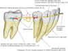
Figure 1 shows the finite element model for simulating orthodontic movement. Assuming symmetry for both sides of the arch, a model of only the right side was constructed. Three-dimensional models of the tooth were constructed on the basis of computed tomography images of a dental study model (i21D-400C; Nissin Dental Products, Kyoto, Japan).12 Each tooth was meshed with shell elements and defined as a rigid body.
The teeth and alveolar bone were assumed to be rigid bodies. The periodontal ligament (PDL) was assumed to be a linear elastic film with a uniform thickness of 0.2 mm, with Young's modulus and Poisson's ratio of 0.13 MPa and 0.45, respectively.13 In order to reduce the number of nodes, each tooth supported by the PDL was replaced with a so-called substructure element. This element had two nodes in which one node corresponded to the tooth and the other node to the alveolar socket.
An archwire was made from 0.018 × 0.025-inch stainless steel wire with Young's modulus and Poisson's ratio were E = 200 GPa and v = 0.3, respectively.14 The diameter of the helical loop was 3 mm, which was a standard configuration used in clinical treatment.9 The loop was incorporated at a distance of 10.5 mm from the molar bracket and was closer to the premolar bracket than the molar bracket. The off-center position of the loop was selected so that the molar bracket would not strike against the loop during space closure. As the molar bracket moved along the archwire, the relative position of the molar and loop, as well as the force system, changed. All of these changes could be included in the finite element simulation. The wire was meshed with elastic solid elements. To reproduce the tip-back and toe-in (antirotation) bends, two bending moments of equal magnitude but in opposite directions, m1 and m2, were applied to adjacent nodes at the top of the loop.
A bracket of 4-mm width and 0.022 × 0.028-inch slot was bonded on the first molar. The bracket was meshed with shell elements and defined as a rigid body. The archwire slid along the bracket slot. The frictional coefficient was assumed to be µ = 0.15, according to other experimental data.15 The archwire was fixed firmly to the anterior teeth at the bracket positions. Symmetrical boundary conditions were applied at the median end of the archwire, and forces of 2 N were applied between the first premolar and first molar brackets.
Orthodontic movement was assumed to occur as a result of the initial movement induced by elastic deformation of the PDL.13 First, the initial movement was calculated by using the finite element model, and then the alveolar socket of each tooth was moved by the same displacement and rotation as the initial movement. By repeating this calculation, the teeth were moved in a step-by-step manner. The force system acting on the teeth was updated at each step. The movement pattern of the teeth changed as the teeth moved. The number of steps, N, corresponded to the time elapsed after force application.
The total number of nodes in the finite element model for simulating the orthodontic movement was 3,287. For the finite element simulation, ANSYS 11 (ANSYS Inc., Canonsburg, PA, USA) was used.
Beam theory
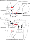
Under translational movement, all forces acting on the molar are illustrated in Figure 2. When applying protractive force P (= 2 N), the archwire contacts the bracket at its edges. Normal contact forces, N1 and N2, produce friction with a frictional coefficient of µ = 0.15. The net force F, which is the resistance to orthodontic movement, acts on the CR. The F is smaller than the protractive force P due to the friction. The distances of the CR from the brackets, L1 and L2, could be determined using the finite element method.
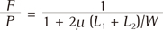
Denoting by W the width of bracket, the equilibrium equations for the moments and forces were obtained as follows; From these equations, the ratio of the net force F to protractive force P became
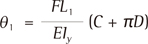
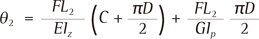
In this case, the moments L1F and L2F were applied to the archwire, and produced a tipping angle θ1 and rotation angle θ2 of the molar. Assuming the archwire to be a cantilever beam clamped at the premolar bracket, θ1 and θ2 could be easily calculated using Castigliano's theorem.16
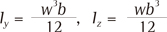
where D (= 3 mm) is the diameter of the loop, and C is the distance between the brackets. Iy, Iz, and Ip are the moments of inertia of the cross-sectional area of the archwire. Using the height w and width b of the archwire, Iy and Iz are expressed as Further, Ip becomes for the rectangular section of w/b = 0.018 inch/0.025 inch = 1.4. For this archwire, the moments of inertia were calculated as Iy = 5.06 × 10⁻³ mm4, Iz = 9.76 × 10⁻³ mm4, and Ip = 21.2 × 10⁻³ mm4. The shear modulus of elasticity G is obtained as G = E/2 (1 + v), where E is Young's modulus and v is Poisson's ratio. For the stainless steel archwire, G was 76.9 GPa.
RESULTS
Finite element simulation
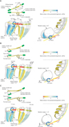
In the case of a running loop without bends, the teeth moved in the following way. Immediately after applying the force, the molar began to tip and rotate because moments acting on the molar were insufficient to prevent these movements. As the tipping and rotation angles increased, elastic deflection of the archwire also increased, thereby increasing the moments. After the molars reached sufficient levels, they continued a translational movement while maintaining the initial tip and rotation. With this movement process, the extraction space was closed at iteration number N = 1,500. At this time, the molar moved mesially by 4.6 mm at the bracket position, tipped mesially by 9.6°, and rotated counterclockwise by 5.4° in the occlusal plane. The first premolar moved almost bodily, and the incisors tipped slightly lingually (Figure 3A).
When applying the moments m1 = 200 Nmm and m2 = 60 Nmm, the tip-back and toe-in angles increased to 11.5° and 9.9°, respectively. In this case, appropriate moments for preventing tipping and rotation were produced from the beginning. The molar moved bodily by almost 2.0 mm at the number of iterations N = 1,500. The tipping and rotation angles were less than 1°. The first premolar and incisors tipped slightly mesially (Figure 3B).
When applying the moments m1 = 320 Nmm and m2 = 50 Nmm, the tip-back and toe-in angles increased to 14.2° and 18.7°, respectively. In this case, excessive moments for bodily movement were produced from the beginning. After the molar tipped and rotated, it translated. At the number of iterations N = 1,500, the molar tipped distally by 4.9° and rotated clockwise by 1.5°. The anterior teeth tipped mesially, and the incisors intruded (Figure 3C).
The tip-back and toe-in angles for achieving bodily movement were about 12° and 10°, respectively. When increasing the tip-back angle from 0° to 14.2°, the movement pattern of the molar changed from mesial tipping to distal tipping. This led to a decrease in the movement distance of the molar at the bracket position.
Friction was produced between the archwire and the bracket, and hence, the net forces acting on the molar became smaller than the protractive force P (= 2 N). When the bending angles of the running loop were increased, the moments acting on the molar increased in the early rotation and tipping movement. In this stage, the frictional force increased and the net force decreased. In the following translational movement, the moments were maintained at levels required for bodily movement; these were fixed values. At this stage, the frictional forces were kept constant and the net forces became 0.8 N irrespective of the bending angles.
Beam theory
For the first molar used in the finite element simulation, distances of the CR from the bracket were determined as L1 = 5.3 mm and L2 = 7.3 mm. In Figure 3A, the distance between the molar and premolar brackets was C = 11.5 mm. Substituting these values in Equations (2) and (3), F/P became 0.515, and the tipping and rotation angles of the molar were θ1 = 8.9° and θ2 = 3.5°, respectively.
DISCUSSION
Comparison with a clinical case
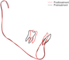
Running loops9 have been used in mandibular second premolar extraction treatment instead of cherry or shoehorn closing loops in the Tweed technique. A running loop archwire is usually made of 0.018 × 0.025-inch stainless steel, with a helical loop 5 mm mesial to the buccal tube. The effective tip-back angle to upright the molars is usually about 20° to 30°, and a slight toe-in is necessary to prevent mesiolingual rotation. In such cases, the molars tipped distally during protraction as shown in Figure 4. This movement pattern was identical to that predicted by the simulation result (Figure 3C). The optimal tip-back angle for achieving bodily movement was estimated to be about 10° by the finite element simulation. However, the optimal angle has not been confirmed in the clinical situations. This confirmation is the subject for a future study.
Finite element simulation
In the case of a running loop without bends, the molar tipped and rotated because of elastic deformation of the wire. By incorporating inverse bends that produce almost similar magnitudes of tipping and rotation angles into the running loop, the molar could be moved bodily. This may be a reasonable result from a mechanical perspective.
In the present case wherein only the molar was protracted with the sliding mechanics, the distal end of the wire was not supported but was left free. The molar was easier to tip and rotate; hence, the tip-back and toe-in bends were necessary to achieve bodily movement.
Orthodontic tooth movement was predicted using the initial tooth movement produced by elastic deformation of the PDL. Both movement patterns were assumed to be similar to each other. The assumption that movement patterns of the orthodontic tooth movement are similar to those of the initial movement will be accepted in clinical experiences. In both movements, movement patterns are controlled by the moment-to-force ratio acting on the tooth. In addition, an in vivo animal experiment indicated that initial tooth displacement was a predictor of long-term orthodontic displacement.17
The PDL was assumed to be a linear elastic material, even though the actual PDL has a nonlinear elastic property. However, within a light force level of approximately 1 N, the initial tooth movement is known to be in proportion to the force,18 namely the PDL is assumed to be a linear elastic material. In addition, a previous study confirmed that the non-linear elastic property of the PDL had little effect on long-term orthodontic tooth movement.13 Under this assumption, a tooth supported with the PDL could be replaced with a substructure element. This element was very useful for reducing the total number of nodes in the finite element model.
The alveolar bone and teeth were assumed to be rigid bodies. This assumption was valid in solid mechanics, because Young's modulus of the alveolar bone and teeth (about 10 GPa) are 100,000 times greater than that of the PDL. Elastic deformation of the alveolar bone and teeth became negligible in comparison with that of the PDL. During in vivo orthodontic tooth movement, resistance to the movement is dependent on the properties of the alveolar bone. In the present study, this effect was not included because of the lack of quantitative data about it in the literature.
In clinical situations, various forces act constantly on the maxillary arch from the mandibular teeth, tongue, and cheek. The magnitude and direction of these forces are infinite, and their effect on orthodontic movement has not yet been clarified. Hence, these forces could not be considered in the present simulation method.
The frictional coefficient between the wire and bracket was assumed to be 0.15 on the basis of an in vitro friction test.15 However, definite values of frictional coefficient are unknown in the clinical setting, wherein various forces act on the wire and bracket; moreover, they may temporarily lose the secure contact between them. If the frictional coefficient becomes small, the net force acting on the molar increases, but the moment remains unchanged. Hence, the moment-to-force ratio decreases, and the molar will be easier to tip mesially.
The number of iterations, N, corresponds to elapsed time. However, N cannot be converted to real time, because the relationship between force magnitude and movement speed has not been clarified. In this simulation, movement speed increases in proportion to the force magnitude.
Beam theory
In order to predict the tipping and rotation angles of a molar, a mechanical model based on the beam theory was proposed. In the beam theory, the running loop was assumed to be clamped at the premolar bracket; thus, the tipping angle of the premolar was 0°. The finite element simulation showed this assumption was valid because the premolar moved almost bodily as shown in Figure 3A. The tipping and rotation angles calculated using the beam theory, θ1 = 8.7° and θ2 = 3.4°, respectively, were close to those in the finite element simulation (i.e., 9.6° and 5.4°, respectively). In the finite element model, the bracket slot (0.022 × 0.028 inch) was larger than the archwire (0.018 × 0.025 inch). There was play between the bracket slot and the archwire. This produced a tipping angle of (0.022 − 0.018) × 25.4/4 = 0.0254 rad = 1.5° and a rotation angle of (0.028 − 0.025) × 25.4/4 = 0.0191 rad = 1.2°. Adding these angles to θ1 and θ2, respectively, namely 8.7° + 1.5° = 10.2° and 3.4° + 1.2° = 4.6°, these values become more close to the results of the finite element analysis. The tipping and rotation angles were predicted by Equations (2) and (3). Therefore, using these equations instead of the finite element simulation is better, and this is the normal method used in mechanical analyses.
In the finite element simulation, the optimal tip-back and toe-in angles were about the same order as the tipping and rotation angles of the molar in the running loop without bends. Based on these relationships, the optimal bend angles for achieving bodily movement can be estimated by Equations (2) and (3). Using Equations (2) and (3), we can also explicitly understand how the tipping and rotation of the molar are produced and can clarify the factors that may affect these angles. This is an advantage of this method over the finite element method.
The tipping and rotation were produced by elastic deformation of the wire, and were hence in proportion to the amount of applied force. For example, when the applied force was decreased by one-half, the tipping and rotation angles also decreased by one-half. Moreover, the kind of material used and the size of the running loop influence these angles through Young's modulus E and the moments of inertia of the cross sections Iz, Iy, and Ip.
The frictional coefficient µ between the running loop and bracket, which is uncertain in the clinical setting, ranges from 0.1 to 0.3.15 This effect can be predicted by using Equations (2) and (3). When the frictional coefficient µ increases from 0.1 to 0.3, the net force acting on the molar decreases from P/F = 0.61 to 0.35. Such a decrease in the net force may be inadequate for efficient tooth movement in a clinical situations. The tipping angle also decreases from 10.6° to 6.0° because of the net force that controls the elastic deflection of the running loop. In the case of a fixed net force, as the friction decreases, the forces applied to the molar and premolar brackets can be decreased, but the movement speed and pattern of the teeth do not change.
When using a narrow-width bracket of W = 3 mm, the net force acting on the molar decreases to P/F = 0.44, and the tipping and rotation angles decrease to 7.7° and 3.0°, respectively. In such cases, a decrease in the tipping and rotation angles is due to a decrease in the net force acting on the molar. It may lead to a decrease in the movement speed of the molar.
When the loop diameter D is decreased, the tipping and rotation angles of the molar decrease. If an archwire without loops is used, namely D = 0, the tipping and rotation angles decrease to 4.9° and 1.8°, respectively. These angles are approximately one-half of those in the running loop. In this case, slight compensation bends are necessary for achieving bodily movement of the molar.
As mentioned above, when the protracting conditions change, we can easily predict the tipping and rotation angles of the molar by using Equations (2) and (3). Moreover, we can predict the optimal bending angles for achieving bodily movement of the molar. This is the most valuable result of this study.
Limitations of study
Our methods were based only on the mechanical laws. Their results are valid within the limits of the assumptions used in the methods. The validity of the essential assumptions was discussed as mentioned above. And the calculated results were compared with a clinical case. However, validation of the methods may not be enough to use it in various orthodontic cases. Further comparisons of the movement patterns calculated by our method with those observed in clinical settings must be necessary. At present, it is difficult to decide the limitations of our study definitely, hence the calculation results should not be accepted uncritically.
CONCLUSION
This study focused on cases of Class II malocclusion in which the mandibular second premolars had been extracted. When the first molar was protracted using the running loop, the optimal bending angles for bodily movement were estimated using the three-dimensional finite element method. The mechanics of the running loop were then clarified by applying the beam theory. The following conclusions were obtained.
1. Bodily movement of the mandibular first molar was achieved during protraction by controlling the tip-back and toe-in angles with the use of a running loop.
2. By using the beam theory, factors influencing the tipping and rotation of the molar could be explicitly elucidated, and hence, the optimal bending angles for bodily movement could be predicted.
 XML Download