Journal List > J Adv Prosthodont > v.8(2) > 1094134

Uzun, Malkoç, Keleş, and Öğreten: 3D micro-CT analysis of void formations and push-out bonding strength of resin cements used for fiber post cementation

Abstract

PURPOSE

To investigate the void parameters within the resin cements used for fiber post cementation by micro-CT (µCT) and regional push-out bonding strength.

MATERIALS AND METHODS

Twenty-one, single and round shaped roots were enlarged with a low-speed drill following by endodontic treatment. The roots were divided into three groups (n=7) and fiber posts were cemented with Maxcem Elite, Multilink N and Superbond C&B resin cements. Specimens were scanned using µCT scanner at resolution of 13.7 µm. The number, area, and volume of voids between dentin and post were evaluated. A method of analysis based on the post segmentation was used, and coronal, middle and apical thirds considered separately. After the µCT analysis, roots were embedded in epoxy resin and sectioned into 2 mm thick slices (63 sections in total). Push-out testing was performed with universal testing device at 0.5 mm/min cross-head speed. Data were analyzed with Kruskal–Wallis and Mann–Whitney U tests (α=.05).

RESULTS

Overall, significant differences between the resin cements and the post level were observed in the void number, area, and volume (P<.05). Super-Bond C&B showed the most void formation (44.86 ± 22.71). Multilink N showed the least void surface (3.51 ± 2.24 mm2) and volume (0.01 ± 0.01 mm3). Regional push-out bond strength of the cements was not different (P>.05).

CONCLUSION

µCT proved to be a powerful non-destructive 3D analysis tool for visualizing the void parameters. Multilink N had the lowest void parameters. When efficiency of all cements was evaluated, direct relationship between the post region and push-out bonding strength was not observed.

INTRODUCTION

For the past two decades, fiber posts have been used for the restoration of endodontically treated teeth with an excessive loss of coronal structure and they have become popular because of their advantageous physical properties.12 Using fiber posts that have a similar elastic modulus to that of dentin reduces stress transmission to the root and lowers the concentration of stress in the post, thus avoiding possible root fractures.3 Fiber posts are passively retained inside the root canal and they are usually cemented into the root with resin cements that have a modulus of elasticity that is similar to both the post and the dentin.45 This relatively mono-block structure, which is composed of dentin, resin cement, and the fiber post, allows for more uniform stress distribution and prevents both vertical cracks in the root and re-infection of the periapical area. It also reduces micro-leakage at the dentin-cement interface.67
Adhesive luting is the ideal method for bonding fiber posts to the root canals.48 The real bond strength at the post-cement-root interface is affected by the restorative procedures that are used, such as the hydration degree of the root-canal dentin, the conditioning agent and cement, the cavity design of the root canal, the sealers, the moisture control, the lack of view into the root canal, and the anatomical and histological characteristics of the root canal, including the orientation of the dentin tubules.19 The bonding strength can also vary among the different levels of the same root canal because the number of dentin tubules decreases toward the apical root. Nonetheless, poor accessibility to the apical third of the root canal makes it more difficult to ideally apply the adhesive agent.4
For the most part, the voids are generated by mechanical air entrapment during handling of the material.10 Formation of voids within the resin bulk represents regions of weakness by lowering the load-bearing capacity of the materials; thus, it affects the mechanical properties of the resin and the survival of the restorations.11 Many clinical studies have reported that debonding as a result of insufficient bond strength is the most common cause of failure for fiber post restorations.1213 Grandini et al.14 reported intensive void formation within the thick cement layer, especially at the coronal level of the fiber post, thereby increasing the debonding tendency. On the contrary, void formation is less likely in a thin and uniform layer of cement.15
Data about the void formation from conventional methods has been provided based on destructive and two-dimensional methods, such as SEM, X-ray, high pressure mercury intrusion porosimetry,16 and stereological volumetric analysis.17 For the destructive techniques, sectioned specimens are used to characterize the structure, and the polymer matrix is damaged on a small scale.15 Furthermore, these methods cannot precisely define the void formation at the volumetric scale.1618 Micro-computed tomography (MCT) has been found to be a non-destructive, rapid, and powerful tool to evaluate the resin matrix. This method allows for examination of the internal structure, mechanical properties, and void detection.192021 Moreover, the structure remains intact and no sectioning is required. It also allows for reconstruction and volumetric evaluation of the internal and external structures either completely or separately, overcoming the limitations of the conventional methods.222324
A variety of tests have been employed for determining the bonding strength of the post in the root canal. However, the push-out bond testing has been shown to be a practical and reliable tool because of the absence of premature failures and the variability of stress distribution. It presents a better estimation of the post retention than a conventional shear bond strength test. The push-out test is used on a thin-sliced root section; thus, stress uniformity is obtained and failure occurs parallel to the post-cement-dentin interface, like in clinical conditions.4 In addition, this method enables the direct measuring of current bonding strength and provides the ability to discriminate the regional differences.
The objectives of this study were to conduct a quantitative evaluation of void formations in three resin cements proposed for the bonding of fiber posts using µCT and to compare the regional push-out bond strength of these resin cements. It was hypothesized that there are no differences among the investigated resin cements in terms of their void characteristics (Hypothesis A), their regional distributions (Hypothesis B), and their push-out bonding strength (Hypothesis C).

MATERIALS AND METHODS

After receiving approval from the ethics committee, 21 straight, one-rooted human maxillary canines and central incisors, freshly extracted for periodontal reasons, with a single, round-shaped root canal were selected. They were decoronated from the cemento-enamel junction using a low speed diamond saw (Isomet 1000, Buehler, Lake Bluff, IL, USA), and stored in 0.1% thymol solution until use. The roots were radiographed in bucco-lingual and mesio-distal projections to verify the round-shaped root canal at a distance of 10 mm from the apex. Teeth with roots having resorption, caries, or cracks, endodontic treatments, posts, or crowns, and a root length of 10 ± 1 mm were excluded. The sample size calculation was obtained by MedCalc Statistical Software 14.12.0 (Ostend, Belgium) considering the use of a binomial two-tailed statistics with 80% power (0.8) and alpha level of 10% able to read a 20% difference between the Malkoç et al.25 article. The sample size was defined as 7 for each group for sample size calculation. The teeth were randomly divided into three experimental groups of seven specimens each and cemented with the different luting agents.
Each root canal was prepared with Revo-S (Micro-Mega, Besançon, France) using a crown-down technique after the working length was determined. Between each instrument change, the canal was irrigated with 5% NaOCl. After root canal preparation, final irrigation with 5 mL of 5% NaOCl was done and the root canals were dried with paper points. The root canals were then filled using a lateral condensation technique. A prefitted gutta-percha cone (Diadent ML 029, Korea) was inserted into the full working length. Lateral condensation was achieved using accessory gutta-percha cones (Diadent ML 029, Korea) until a #25 finger spreader (Antaeos, VDW, Germany) could penetrate no more than 3 mm into the canal. AH Plus (Dentsply DeTrey, Konstanz, Germany) was used as a sealer. Access cavities were temporarily filled with Cavit (3M ESPE, Seefeld, Germany) after coronal excess was removed with a heated excavator. The roots were then stored in 100% humidity at 37℃ for one week to allow complete setting of the sealer.
After 24 hours in water storage at 37℃, gutta-percha was removed using Gates-Glidden burs (sizes 1-4) in descending order, leaving at least 3 mm of the apical seal. The root canals of each specimen were enlarged with a low-speed drill provided by the post manufacturer. The working depth of the post space was 9 mm. With the intention of removing the smear layer, a final flush was performed with 2 mL/min 15% EDTA, followed by 2 mL 5% NaOCl. Finally, the flushed root canals were dried with paper points. The root shaped UniCore glass fiber posts (1.2 mm diameter) were tried in, cleaned with alcohol, and inserted using three different adhesive luting cements. The resin cements and the post systems used in this study are listed in Table 1. The manufacturer's instructions were strictly followed during the cementation of the post.
In Group 1, the posts were cemented with dual-cure Maxcem Elite self-etched, self-adhesive resin cement. After the root canal walls were cleaned and gently air dried without desiccation, the resin cement was mixed with a dual syringe cartridge with curved tips and dispensed onto the post and into the canal space. Then, the fiber post was seated properly into the canal and was vibrated slightly to avoid any air voids. Excess resin cement was removed in its gel state with a scaler after 5 seconds of light curing. After removal of the excess cement, the fiber post was polymerized with a halogen lamp (Woodpecker Zhengzhou Smile Dental Equipment Co., Ltd., Zhengzhou, Henan, China) for 20 seconds from the top of the post. The Group 2 specimens were luted with Multilink N self-cured resin cement. Monobond-S was applied to the post surface with a micro-brush and the material was allowed to react for 60 seconds. The bond was dispersed with strong stream and oil-free air. Multilink N Primer A/B was mixed in a 1:1 ratio and applied to both the root canal and the post surface for about 15 seconds each using thin micro-brushes; they were then gently dried with oil-free air. Excess material was removed from the canal using a paper point. The fiber post surface was coated with the mixed Multilink N cement, which was dispensed from the automix syringe, and the post was placed into the root canal space. The cement was then light-cured for 20 seconds to ensure that the post remained in place. The Group 3 posts were cemented with Super-Bond C&B, according to the bulk-mix technique. An "activated liquid" was obtained by mixing Monomer and Catalyst V. Polymer powder was added to the activated liquid and it was stirred with a brush supplied from the manufacturer. After mixing, the cement was carried to the post surface and post space using a brush, and the post was immediately inserted into the canal and held in position until the cement was completely set. Excessive cement was removed.
Each specimen was scanned using a µCT scanner (SkyScan 1172; Bruker-microCT, Kontich, Belgium). The X-ray tube was operated at 85 kV and 118 µA using a 0.5 mm Al + Cu filter with a resolution of 13.7 µm pixels. Scanning was performed by 360° rotation around the vertical axis, camera exposure time of 930 ms, rotation step of 0.5°, frame averaging of 3, random movement of 20. Each specimen was scanned for a total of 60 minutes. The resulting two dimensional images (8-bit TIFF) were used to reconstruct axial cross-sections. Images of each specimen were reconstructed using NRecon v.1.6.3 software (Bruker-microCT). Following post regions of interest were selected: apical third, middle third, and coronal third. Each specimen was evaluated using CTAn v.1.12 software (Bruker-microCT) to obtain the volume of interest, the number, surface area, and volume of each voids between the dentin and the post. CTVol v.2.2.1 software (Bruker-microCT) was also used for three-dimensional visualization and qualitative evaluation of the void formations.
After the µCT analysis, the restored roots were embedded in epoxy resin (Imicryl, Konya, Turkey) for push-out bond strength testing. Each root was sectioned into 2 mm thick slices (a total of 63 sections) at 1 mm, 4 mm, and 7 mm below the cemento-enamel junction. The thickness of the sections was verified with a digital caliper (accuracy of 0.01 mm). Before testing, all of the sections were controlled with a stereomicroscope (Wild M5A, Heerbrugg, Switzerland) to reduce the potential defects caused by cutting.
Push-out testing was performed with a universal testing device (Model 5565; Instron Co. Ltd., Norwood, MA, USA) at a cross-head speed of 0.5 mm/min. The load was applied in the apical–coronal direction until the post was completely dislodged. The failure load was recorded in Newton (N) and converted in MPa by dividing the applied load (N) by the bonded area (A). Because of cylindrical post shape, the bonding area was calculated using the formula: A = where r is the post radius (0.6), π is the constant 3.14, and h is the thickness of each post section (2 mm).
A comparison of the void parameters was performed by calculating means for the different types of resin cements and the different sections. Non-parametrical analyses were performed to evaluate differences between the groups. Overall comparisons were performed using the Kruskal–Wallis test. In case of significance, pairwise comparisons were performed using the Mann-Whitney U test. The level of statistical significance was set at α=0.05. All analyses were done using the statistical software package SPSS 17 (SPSS Statistics for Windows, Version 17.0, SPSS Inc., Chicago, IL, USA).

RESULTS

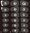
The used resin cement was found to significantly affect the void parameters (P < .05) (Fig. 1). Overall significant differences between the resin cements and the post level were observed for the void number, area, volume (P < .05). When looking at the results, for the Multilink N cement, both the void parameters and their regional distributions were found to be generally compatible with each other. However, for the Maxcem Elite and Super-Bond C&B cements, the void parameters and their distributions among the different root regions varied.
The detected void formation obtained from high resolution µ-CT images in different resin cements and their distributions among the post regions are presented in Table 2. According to the Kruskal-Wallis test results, the void formation in different resin cements was statistically different. Among the tested cements, Super-Bond C&B showed the most common void formation, and void formations into the apical third section were higher than the other types of cements (P < .05).
Regional distributions of the void formations in all of the resin cements were homogeneous as determined by the post levels (P < .05).
The measured void areas are shown in Table 3. Multilink N showed the least overall mean void surface (3.51 ± 2.24 mm2) among the tested cements (P < .05). There was no significant difference between the total void sizes of Maxcem Elite (12.27 ± 3.92 mm2) and Super-Bond C&B (13.80 ± 5.25 mm2). However, the distribution of these void areas among the post levels varied. In the apical third, while Multilink N had the smallest void surface (0.53 ± 0.32 mm2), Maxcem Elite had the widest (3.62 ± 1.26 mm2) (P < .05). The void sizes were homogenous and were not different from each other in the middle third region (P < .05). The largest void areas were measured in the coronal third of the posts. At the coronal third, the measured void surface area (9.06 ± 3.41 mm2) for Super-Bond C&B increased strongly (P < .05). Multilink N also had the smallest (1.63 ± 1.17 mm2) void area (P < .05).
The distributions of the void areas among the post levels were homogeneous for Multilink N and Maxcem Elite. However, for Super-Bond C&B, while the regional distribution of the void formations was regular, the surface area of the voids in the coronal third was larger—about three times larger than the middle third and five times larger than the apical third.
Among the tested cements, there were significant differences only at the apical level (P < .05) (Table 4). Multilink N (0.01 ± 0.01 mm3) had the lowest void volume as compared to both Maxcem Elite (0.12 ± 0.09 mm3) and Super-Bond C&B (0.04 ± 0.02 mm3) at the apical level (P < .05). The void volumes at the other root levels and the total void volumes of the different resin cements were not different.
For all the cements, the void volume increased in the coronal direction. However, for Maxcem Elite and Multilink N the void volume for the coronal third was not different from the void volume of the other parts (apical and middle), based on the findings from the root regions. However, for Super-Bond C&B the post levels were significantly voluminous in the voids from the apical direction to the coronal direction (P < .05).
Data from the push-out bond strength are represented in box-plots in Fig. 2. There was no significant difference among the tested resin cements and the post regions (P > .05). While, the lowest bond strength for all of the cements was observed at the apical third of the posts, the highest bond strength was observed at the coronal third (range: 19 - 20 MPa). Overall, it appeared that the push-out bond strength was not correlated with the void parameters.

DISCUSSION

In the present study, the void characteristics, push-out bond strength of different resin cements, and their regional distributions were evaluated by MCT and push-out bond testing. The results showed that the void parameters and their regional distributions were affected by the types of cements that were used. However, no relationship was found among the types of resin, the void parameters, and the regional push-out bonding strength. Thus, the hypotheses that the adhesive cement type does not affect the void parameters (Hypothesis A) and the regional distributions of the void characteristics (Hypothesis B) were rejected. The hypothesis that the push-out bond strength of resin cements (Hypothesis C) does not vary among the post levels, was accepted.
The micro-CT technique could help overcome some of the disadvantages of the methods generally used to assess the post-cement-dentin complex as it is nondestructive. It gives an accurate three-dimensional view of the root canal content without destroying the samples, and that data can be used for further study.22 With the help of 3D reconstruction, information about the complete restorations and the distribution of their components can be obtained.19 The current study shows that it is possible to distinguish between resin cement, fiber post, and voids.
Void formation is mainly a result of air entrapment in the material during the mixing process. However, for fluid material, indirect void formation is possible through the linking of minor bubbles.26 When the data were examined, it could be seen that the number of void formations was distributed evenly among the different root levels. Yet, the number of void formations in the apical third and the total void formations of the Super-Bond C&B cement were greater than that of the Maxcem Elite and Multilink N cements. Maxcem Elite and Multilink N were applied using the injection method and SuperBond C&B was mixed mechanically. It was assumed that the different mixing method influenced void formation in the dental cements. This fact makes the injection method more advantageous in comparison to hand mixing. Boschian Pest et al.5 and Milutinović-Nikolić et al.16 showed that hand-mixed conventional cements contain more and larger voids than capsulated cements, providing less void formation in the injection resin cements. Our results were also consistent with their findings.
The smallest void surface area and volume for all of the cements was observed at the apical third and the largest void surface area and volume was obtained at the coronal third (Fig. 3). The number of void formation, their surface area, volume, and distribution among the root levels were compatible in the Multilink N cement. In the Maxcem Elite cement, fewer, wider, and more voluminous voids were formed; in Super-Bond C&B cement, a large number of narrow and small voids were observed. However, there was no difference between the total void surfaces and the volumes for both of those types of cements. The total void surface and volume in the Maxcem Elite cement were shared proportionally by post levels (P > .05), whereas in the Super-Bond C&B cement, both the total surface and the volume intensified significantly at the coronal level (P < .05). In Maxcem Elite and Multilink N, the resin cement is carried into the root canal with the help of fine application tips in uniform consistency. After that, the fiber post that is covered by the resin cement is placed into the root canal by making the final position through a small vibration, after which the polymerization is completed. The mild vibration increases the adaptation on the post cement and the cement dentin interfaces, which helps eliminate the void formations in the cement layer. In dual syringe mixed resin cements, mixing cement is in the form of two pastes without voids by using a mixing tip, and vibration in the course of the post insertion, are two determining factors that affect void formations. This can explain the more homogeneous dispersion of the void parameters among the post levels in the Multilink N and MaxCem Elite cements that are mixed by injection method. On the other hand, Super-Bond C&B is mixed manually and more fluid than the other types of cement that were used. Super-Bond C&B cementincludes a lot of small void formations, both during the mixing and while placing the post into the canal. The applied mild vibration caused movement of the voids from the apical third region to the coronal third region. The voids that could not be eliminated accumulated in the coronal third region and generated larger voids when the small void formations were combined. This condition may be a possible reason for the increase in the void surface and volume at the coronal third level in the Super-Bond C&B cement.
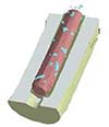
The fact that the coronal third of all the tested cements showed wider and more larger voids compared to the other root levels suggests that this level demonstrates some biomechanical risks that can affect the success of restoration. When three-dimensional models thatwere obtained by reconstructions of high resolution micro-CT images, were analyzed, it was observed that in some cases, there were voids in continuity from the coronal level to the apical level of the fiber post and some of them remained as local voids (Fig. 4 and Fig. 5). From a biological standpoint, void formations may act as a way for microorganisms to pass from the coronal to the peri-apical area.27 Closed voids that are not linked to the dentin and post surface, could be considered to be clinically less significant than open voids. The open voids that are in continuity along both interfaces of the post may necessitate retreatment. On the other hand, it may cause easier dissolution of the resin cement and dislodgement of the post-core restoration under functional stresses.2728 Maccari et al.29 and Barcellos et al.30 showed that the main failure of teeth restored with fiber posts originated from fracturing of the coronal reconstruction. It is important to consider the role that wide and voluminous void formations that are localized at the coronal third play in post-core success.31 According to the analyzed parameters, Multilink N cement presented the most desired structure among the investigated cements for post application. This type of cement had the lowest number of void formations and the smallest area and volume.
Another notable negative effect of void formations is that they decrease the bonding strength by restricting the available area for cementation, which results in shortened survival time of the restoration. Yet, the effect of the void parameters on the push-out bonding strength of fiber posts to the dentinal walls of the canal could not be verified by the results of this study. According to this study's outcomes, although the void parameters were affected by the type of cement used and by the root regions, all of these factors could not induce a significant effect on the push-out bonding strength, thereby supporting the Hypothesis C. Therefore, a negative correlation is expected between the void parameters and the mechanical properties of the material.32 Consistent with this finding, Nomoto and McCabe26 analyzed the fractured surfaces of GIC specimens by SEM and they showed that the specimens with low compressive strength had larger voids. They suggested that the presence of those large voids might be due to differences in compressive strength. In the current study, although the highest push-out bond strengths were obtained at the coronal level and the lowest push-out bond strengths were obtained at the apical level for all of the used cements, no difference was observed in the overall push-out bond strengths between the types of cement. No correlation was found between the void parameters and the push-out bond strength. Serafino et al.33 reported higher debris, a thicker smear-layer, and more remnants of gutta-percha and endodontic sealer at the apical third than the middle and coronal third of the root. They also showed the least open dentinal tubules, which may be the cause of the reduced push-out bond strength. These data may explain the lower push-out strength, although the lowest void parameters were obtained at the apical third level. The coronal third of roots have a greater potential to be free of all remnant areas and many more open dentinal tubules for micromechanical bonding as compared to the medial third and apical third regions. As it can be perceived from the push-out testing results, these explained factors can diminish the negative effects that the void parameters have on the cement bond. It is still more crucial that the dentinal walls be thoroughly cleared of all residues, which reduces the available area for achieving strong adhesive cementation in endodontically treated teeth, than to consider the void parameters. Overall, this study's outcome also coincides with the findings from previous studies134, 35, 36 that investigated the influence of the root region on the pushout bond strength.
Boschian Pest et al.5 reported the void formations of varying numbers and sizes in resin cements cured with different methods. But, mixing method have greater influence on void formations than the polymerization method of resin cement. Accordingly, formation of voids does not originate from a technical error in the cementation process but from the mixing stage of the paste with catalysis of cement. This present study used both dual- and self-cured resin cements. In accordance with the previous outcomes, the curing mode had no direct determinative effect on either the void parameters or the push-out bond strength. The less void formations were expected by injection technique regardless of the type of resin used. Our results also confirmed that the injection method caused the less and smaller void formations than the manual mixing method (Table 2 and Table 3).
Future investigations should focus on different methods to reduce the void formations that occurred during the insertion of fiber post into the root canal and to eliminate the voids formed by combining small voids at the coronal level of root.

CONCLUSION

Within the limitations of the study, the following conclusions can be drawn. There were certain amounts of void formations inside all of the tested resin cements. In general, the void parameters increased in the apical-coronal direction. According to the analyzed parameters, Multilink N had the lowest void parameters among the investigated cements. Based on the results of the push-out testing, there was no direct relationship between the post region and push-out bonding strength was observed. The void formations inside the resin cement layer must be studied more extensively for their biological aspects rather than for their mechanical aspects.

Figures and Tables

Fig. 1

Representative micro-CT cross-sections (interval of 500 µm) from the coronal, middle and apical thirds of fiber posts with different resin cement. In the Maxcem Elite cement, fewer, wider, and more voluminous voids (black spots within the cement layers) were formed (A). Multilink N cement had the lowest number of void formations and the smallest area and volume (B). In Super-Bond C&B cement, a large number of narrow and small voids were observed (C).

jap-8-101-g001
Fig. 2

Regional push-out bonding strength of used resin cements. The highest bond strength was obtained at the coronal level.

jap-8-101-g002
Fig. 3

Representative image of 3D model of voids. (A) Continuous void formations along the fiber post were wider at coronal third. Insizal view (B) Viewing of same specimen from aproximal (C), (D) Localized void formations in middle third from insizal and aproximal.

jap-8-101-g003
Fig. 4

(A) Representative images of detected circumferential and open voids in Maxcem Elite. Open voids may act as microbial pathway and penetration area. (B) localized and closed voids in Super Bond C&B. Closed voids weakens the resin cement mechanically. But they protects the interior of tooth from penetration of oral fluids, bacteria and bacterial toxins (D: dentine, C: resin cement, P: post, V: void).

jap-8-101-g004
Fig. 5

A representative 3D model of fiber post and dispersion of void formations in continuity of post. It is seen that the void formations were the distribution of equal proportion and size in all root region.

jap-8-101-g005
Table 1

Used adhesive resin cements and post system

jap-8-101-i001
Product/Activation mode/Lot number Bonding system Package/Type Composition Manufacturer
Maxcem Elite/Dual cured/3283155 Primer A + Primer B
Base + Catalyst
Self-etch / Self-adhesive dental cement
GPDM, Glass, oxide, chemicals, ytterbium trifluoride, methacrylate ester monomers, HEMA, 4 methoxyphenol, cumene hydroperoxide, titanium dioxide and pigments Kerr, Germany
Multilink N/Self-cured/G10444 Primer A + Primer B
Base + Catalyst
Self-etch / one-step
Primer A: 2,2'-[(4-methylphenyl)imino]bisethanol
Primer B: HEMA, phosphoric acid acrylate
Base: Ytterbium trifluoride, ethyoxylated bisphenol
Adimethacrylate, Bis-GMA, 2-HEMA, 2-dimethylaminoethyl methacrylate
Catalyst: Ytterbium trifluoride, ethyoxylated bisphenolA dimethacrylate, urethane dimethacrylate, 2-HEMA,dibenzoyl peroxide
Ivoclar, Vivadent, Liechtenstein
Super Bond C&B/Self-cured/GF1 Monomer + Polymer
Self-etch
Monomer: MMA, 4-META
Polymer: PMMA, metal oxides
Catalyst V: TBB-O, hydrocarbon
Sun Medical, Shiga, Japan
Post system UniCore post/100705 Glass fibers/Translucent/Post#3 Blue 1.2 mm Pre-activated fibers, encased in a bondable resin
Matrx
Ultradent, South Jordan, USA

GPDM: Glycerol phosphate dimethacrylate, HEMA: Hydroxyethyl methacrylate, Bis-GMA: Bisphenol A glycidyl methacrylate, MMA: Methyl-methacrylate, 4-META: 4-methacryloxyethyl-trimellitic anhydride, TBB-O: Partially oxidized tri-n-butylborane, PMMA: Polymethylmethacrylate

Table 2

Void formations and regional distributions*

jap-8-101-i002
Maxcem Elite Multilink N Super Bond C&B
Mean ± SD Median Mean ± SD Median Mean ± SD Median
A 3rd 7.71 ± 2.81a 9 5.71 ± 3.15a 6 16.00 ± 5.97b 16
M 3rd 7.29 ± 2.36 6 6.00 ± 5.48 4 13.14 ± 9.63 10
C 3rd 8.29 ± 4.31 6 6.43 ± 4.28 5 15.86 ± 10.12 12
Total 23.29 ± 5.31a 21 18.14 ± 11.60c 16 44.86 ± 22.71b 33

*: A different superscript letter shows the statistically significance between the resin cements (P < .05).

Table 3

Void areas and regional distribution (mm2)*

jap-8-101-i003
Maxcem Elite Multilink N Super Bond C&B
Mean ± SD Median Mean ± SD Median Mean ± SD Median
A 3rd 3.62 ± 1.26a 3.47 0.53 ± 0.32b 0.53 1.70 ± 0.87c,¥ 1.64
M 3rd 3.70 ± 2.32 3.25 1.36 ± 1.08 1.38 3.04 ± 1.60¥ 2.59
C 3rd 4.95 ± 2.04a 5.11 1.63 ± 1.17b 1.52 9.06 ± 3.41c,£ 9.26
Total 12.27 ± 3.92a 13.55 3.51 ± 2.24b 3.44 13.80 ± 5.25a 13.79

*: different superscript letters shows significant differences among the resin cements. A different superscript sign also shows the regional differences (P < .05).

Table 4

Void volume and regional distribution (mm3)*

jap-8-101-i004
Maxcem Elite Multilink N Super Bond C&B
Mean ± SD Median Mean ± SD Median Mean ± SD Median
A 3rd 0.12 ± 0.09a 0.10 0.01 ± 0.01b 0.01 0.04 ± 0.02a,¥ 0.04
M 3rd 0.22 ± 0.26 0.13 0.06 ± 0.08 0.04 0.12 ± 0.09£ 0.12
C 3rd 0.40 ± 0.38 0.32 0.26 ± 0.41 0.04 0.55 ± 0.28ł 0.62
Total 0.74 ± 0.51 0.57 0.34 ± 0.48 0.08 0.71 ± 0.34 0.78

*: different superscript letters shows significant differences among the resin cements. A different superscript sign also shows the regional differences (P < .05).

Notes

This study was supported by Scientific Research Project Department of Inonu University with 2012/72 number.

References

1. Zicari F, Couthino E, De Munck J, Poitevin A, Scotti R, Naert I, Van Meerbeek B. Bonding effectiveness and sealing ability of fiber-post bonding. Dent Mater. 2008; 24:967–977.
2. Baba NZ, Golden G, Goodacre CJ. Nonmetallic prefabricated dowels: a review of compositions, properties, laboratory, and clinical test results. J Prosthodont. 2009; 18:527–536.
3. Spazzin AO, Galafassi D, de Meira-Júnior AD, Braz R, Garbin CA. Influence of post and resin cement on stress distribution of maxillary central incisors restored with direct resin composite. Oper Dent. 2009; 34:223–229.
4. Goracci C, Grandini S, Bossù M, Bertelli E, Ferrari M. Laboratory assessment of the retentive potential of adhesive posts: a review. J Dent. 2007; 35:827–835.
5. Boschian Pest L, Cavalli G, Bertani P, Gagliani M. Adhesive post-endodontic restorations with fiber posts: push-out tests and SEM observations. Dent Mater. 2002; 18:596–602.
6. Furuya Y, Huang SH, Takeda Y, Fok A, Hayashi M. Fracture strength and stress distributions of pulpless premolars restored with fiber posts. Dent Mater J. 2014; 33:852–858.
7. Ferrari M, Cagidiaco MC, Goracci C, Vichi A, Mason PN, Radovic I, Tay F. Long-term retrospective study of the clinical performance of fiber posts. Am J Dent. 2007; 20:287–291.
8. Bergoli CD, Amaral M, Boaro LC, Braga RR, Valandro LF. Fiber post cementation strategies: effect of mechanical cycling on push-out bond strength and cement polymerization stress. J Adhes Dent. 2012; 14:471–478.
9. de Durâo Mauricio PJ, González-López S, Aguilar-Mendoza JA, Félix S, González-Rodríguez MP. Comparison of regional bond strength in root thirds among fiber-reinforced posts luted with different cements. J Biomed Mater Res B Appl Biomater. 2007; 83:364–372.
10. Lundström TS, Gebart BR. Influence from process parameters on void formation in resin transfer molding. Polymer Composites. 1994; 15:25–33.
11. Drummond JL. Degradation, fatigue, and failure of resin dental composite materials. J Dent Res. 2008; 87:710–719.
12. D'Arcangelo C, Cinelli M, De Angelis F, D'Amario M. The effect of resin cement film thickness on the pullout strength of a fiber-reinforced post system. J Prosthet Dent. 2007; 98:193–198.
13. Rasimick BJ, Wan J, Musikant BL, Deutsch AS. A review of failure modes in teeth restored with adhesively luted endodontic dowels. J Prosthodont. 2010; 19:639–646.
14. Grandini S, Goracci C, Monticelli F, Borracchini A, Ferrari M. SEM evaluation of the cement layer thickness after luting two different posts. J Adhes Dent. 2005; 7:235–240.
15. Nazari A, Sadr A, Shimada Y, Tagami J, Sumi Y. 3D assessment of void and gap formation in flowable resin composites using optical coherence tomography. J Adhes Dent. 2013; 15:237–243.
16. Milutinović-Nikolić AD, Medić VB, Vuković ZM. Porosity of different dental luting cements. Dent Mater. 2007; 23:674–678.
17. Geirsson J, Thompson JY, Bayne SC. Porosity evaluation and pore size distribution of a novel directly placed ceramic restorative material. Dent Mater. 2004; 20:987–995.
18. del Valle S, Miño N, Muñoz F, González A, Planell JA, Ginebra MP. In vivo evaluation of an injectable Macroporous Calcium Phosphate Cement. J Mater Sci Mater Med. 2007; 18:353–361.
19. Jung M, Lommel D, Klimek J. The imaging of root canal obturation using micro-CT. Int Endod J. 2005; 38:617–626.
20. Keleş A, Alcin H, Kamalak A, Versiani MA. Micro-CT evaluation of root filling quality in oval-shaped canals. Int Endod J. 2014; 47:1177–1184.
21. Keles A, Ahmetoglu F, Uzun I. Quality of different guttapercha techniques when filling experimental internal resorptive cavities: a micro-computed tomography study. Aust Endod J. 2014; 40:131–135.
22. Swain MV, Xue J. State of the art of Micro-CT applications in dental research. Int J Oral Sci. 2009; 1:177–188.
23. Kato A, Ohno N. Construction of three-dimensional tooth model by micro-computed tomography and application for data sharing. Clin Oral Investig. 2009; 13:43–46.
24. Keleş A, Alcin H, Kamalak A, Versiani MA. Oval-shaped canal retreatment with self-adjusting file: a micro-computed tomography study. Clin Oral Investig. 2014; 18:1147–1153.
25. Malkoç MA, Sevimay M, Tatar İ, Çelik HH. Micro-CT Detection and Characterization of Porosity in Luting Cements. J Prosthodont. 2015; 24:553–561.
26. Nomoto R, McCabe JF. Effect of mixing methods on the compressive strength of glass ionomer cements. J Dent. 2001; 29:205–210.
27. Asheibi F, Qualtrough AJ, Mellor A, Withers PJ, Lowe T. Micro-CT evaluation of the effectiveness of the combined use of rotary and hand instrumentation in removal of Resilon. Dent Mater J. 2014; 33:1–6.
28. Ng YL, Mann V, Rahbaran S, Lewsey J, Gulabivala K. Outcome of primary root canal treatment: systematic review of the literature - Part 2. Influence of clinical factors. Int Endod J. 2008; 41:6–31.
29. Maccari PC, Conceição EN, Nunes MF. Fracture resistance of endodontically treated teeth restored with three different prefabricated esthetic posts. J Esthet Restor Dent. 2003; 15:25–30.
30. Barcellos RR, Correia DP, Farina AP, Mesquita MF, Ferraz CC, Cecchin D. Fracture resistance of endodontically treated teeth restored with intra-radicular post: the effects of post system and dentine thickness. J Biomech. 2013; 46:2572–2577.
31. Kainose K, Nakajima M, Foxton R, Wakabayashi N, Tagami J. Stress distribution in root filled teeth restored with various post and core techniques: effect of post length and crown 3D micro-CT analysis of void formations and push-out bonding strength of resin cements used for fiber post cementation height. Int Endod J. 2015; 48:1023–1032.
32. Baudin C, Osorio R, Toledano M, de Aza S. Work of fracture of a composite resin: fracture-toughening mechanisms. J Biomed Mater Res A. 2009; 89:751–758.
33. Serafino C, Gallina G, Cumbo E, Ferrari M. Surface debris of canal walls after post space preparation in endodontically reated teeth: a scanning electron microscopic study. Oral Surg Oral Med Oral Pathol Oral Radiol Endod. 2004; 97:381–387.
34. Pereira JR, Lins do, Ghizoni JS, Lorenzoni FC, Ramos MB, Dos Reis. Push-out bond strengths of different dental cements used to cement glass fiber posts. J Prosthet Dent. 2013; 110:134–140.
35. Kalkan M, Usumez A, Ozturk AN, Belli S, Eskitascioglu G. Bond strength between root dentin and three glass-fiber post systems. J Prosthet Dent. 2006; 96:41–46.
36. Chen Q, Cai Q, Li Y, Wei XY, Huang Z, Wang XZ. Effect on push-out bond strength of glass-fiber posts functionalized with polydopamine using different adhesives. J Adhes Dent. 2014; 16:177–184.
TOOLS
ORCID iDs

İsmail Hakkı Uzun
https://orcid.org/http://orcid.org/0000-0002-4165-7688

Meral Arslan Malkoç
https://orcid.org/http://orcid.org/0000-0002-7361-7242

Ali Keleş
https://orcid.org/http://orcid.org/0000-0002-6834-4307

Ayşe Tuba Öğreten
https://orcid.org/http://orcid.org/0000-0003-4707-5432

Similar articles