

 PDF
PDF ePub
ePub Citation
 Print
Print


I. Introduction
Biomechanics is a useful tool to predict bone response, which strongly affects the durability of dental implants. Finite element analysis (FEA) is an effective way to predict the mechanical and thermal behaviors of dental implants in their bio-environment. This analysis enables researchers to gain information about the nature of the biting load and the induced stress and strain in the dental implant and surrounding bone. Considering the benefits of FEA, it is used to evaluate the biomechanics of customized dental implants and optimize the mechanical features of their design12. Thread shape and geometry are important in biomechanical optimization of dental implants. Threads are used to maximize preliminary contact, improve initial steadiness, enlarge the outside area of the implant, and favor dissipation of interfacial stress. Optimization of dental implant thread design can improve clinical success34. Petrie and Williams5 introduced the design optimization of an endosseous dental implant in order to minimize cortical bone strain at the crest of the implant/bone interface. Linear and two-dimensional elastic p-version FEA was used to find the optimal design in four different two-dimensional finite element (FE) models of the mandibular bone5. Shi et al.6 used a topological shape optimization technique (soft kill option) to find alternative implant shapes to minimize the concentration of stress at the shoulder level of the implant. This technique mimicked biological growth, in conjunction with a two-dimensional FE method to optimize the shape of a dental implant under loads. Mahajan and Patil3 executed three-dimensional FEA with static loading to find the optimal addithread shape. They evaluated two different implant thread shapes and assessed the stress induced in the surrounding cortical and cancellous bone. Chang et al.7 took advantage of the topology optimization in the FE method to look for redundant material distribution on a threaded dental implant and redesigned a new implant and evaluated its biomechanical functions. The FE model estimated that the volume of the new implant could be reduced by 17.9% of the traditional one with the same biomechanical performance, such as stress in the implant and stress in the implant-bone complex with lower displacement, and greater stiffness than the traditional implant. Shen et al.8 used bivariate analysis to determine the optimal ranges of thread height and pitch in mini-implants and realized that maxillary stress and mini-implant stability were influenced by mini-implant thread height and pitch. Hasan et al.9 aimed to predict the distribution of bone trabeculae, as density change per unit time, around a dental implant based on a selected mathematical remodeling model. The apparent bone density change as a function of mechanical stimulus was the basis of the applied remodeling model that describes disuse and overload bone resorption. The simulation was tested in an FE model of a screw-shaped dental implant in an idealized bone segment. The analysis of sensitivity to different parameters was also performed and showed that alteration in the mechanical parameters had a significant influence on density distribution and model stability, particularly in the cortical bone. In our previous study, we assessed stress and strain patterns in cortical and cancellous bone surrounding three newly designed dental implants with different thread patterns. Model 1 had V-shaped threads; model 2 had micro threads in the upper area and V-shaped threads in the rest of the body; model 3 had reverse buttress threads in all areas. The study analyzed the static, dynamic, and fatigue behaviors of dental implants using FEA, and implant model 2 was chosen as the best model for a desirable dental implant1011. However, the optimal thread parameters for this implant have not yet been determined. In the present study, the chosen model was examined by means of optimization method in FEA, and thread parameters were optimized to achieve an optimal stress distribution pattern. In addition, the sensitivity of the simulation to different mechanical parameters was evaluated.
Go to : 
II. Materials and Methods
1. Computer-aided design modeling
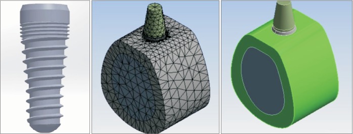
Modeling and analysis of the implant were done using ANSYS Workbench software (ANSYS WB 2.0 Framework ver. 12.0.1; 2009 SAS IP, Tehran, Iran). The screw had a length of 10.5 mm and diameter of 3.8 mm. The implant neck was beveled by a 22° angle relative to the vertical axis. The implant neck had a height of 0.5 mm and had to remain outside of the bone. The area beneath the beveled margin had a 1 mm height with no threads and was designed to be placed in the cortical bone. The rest of the body had a specific thread design to evaluate the effect of thread design on stress distribution. The implant had 1.3 mm micro-threads on the upper part, and the rest of the body had V-shaped threads. In addition, the implant body had an 8° taper. A fixed rigid abutment with 5 mm height was placed on top of the screw, where the force was applied. A bone block, 17 mm high and 12 mm wide, was built around the imported implants, representing the surrounding bone in the second premolar region. A core of cancellous bone was covered with a thick layer of cortical bone with a constant thickness of 2 mm1011. The screw model and the whole model with meshing condition are shown in Fig. 1.
2. Material properties
3. Finite element analysis
The physical interactions at all surfaces during loading were taken into account through bonded surface-to-surface contact features of ANSYS, and the base of the mandible was considered to be fixed. The FE model consisted of 44,922 four-node tetrahedron elements, 13,269 elements for the implant, 13,231 elements for the cortical bone, and 18,422 elements for the cancellous bone. In this study, the implant was subjected to axial static loading of 100 N1011.
4. Optimization
Design of experiments (DOE) is generally used to effectively sample a design space, so that a statistical model can be built to predict responses of a given design. DOE is useful when one can only sample a limited number of points and run a limited number of simulations. The key idea of DOE is to spread out the samples so that the resultant statistical model has low uncertainty in its estimation and thus high accuracy in prediction.
The process was done by means of response surface optimization, which is one of the main methods of optimization in Ansys Workbench. To conduct DOE for a given model, the list of design variables and objectives of interest (input and output parameters) should be defined first. Four main parameters were used as input parameters including depth and pitch of the two thread models. Each parameter has a specific range, which is input to the software. These ranges are shown in Table 2. The output parameters were maximum von-Mises stress and strain in the model, which were defined by the optimization process.

5. Sensitivity analysis
Design sensitivity analysis plays a critical role in inverse and identification studies, as well as numerical optimization and reliability analyses1314. The main goal of sensitivity analysis was to gain insight into critical input parameters. In this study, sensitivity analysis was also done along with the optimization process and showed more critical parameters in the model.
Go to :
III. Results
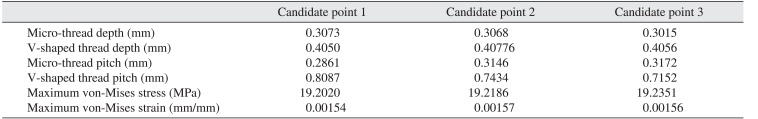
The screening optimization method uses a simple approach based on sampling and sorting. It supports multiple objectives and constraints as well as all types of input parameters. Usually, it is used for preliminary design, which may require additional methods for more refined optimization results. The software generates 1,000 samples (Fig. 2) and finds three candidates, which are presented in Table 3 and also shown in Fig. 3.
 | Fig. 2Iterations of solving the problem to find the perfect candidates to optimize the chosen parameters.
|
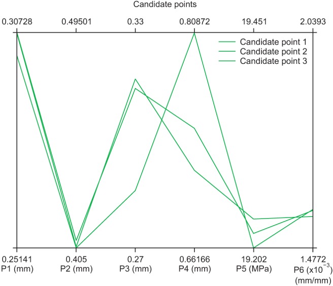 | Fig. 3Three candidate points for output results (P1: microthread depth, P2: V-shaped thread depth, P3: micro-thread pitch, P4: V-shaped thread pitch, P5: maximum von-Mises stress, P6: maximum von-Mises strain).
|
Table 3
Candidate points produced by the response surface optimization method
![]()
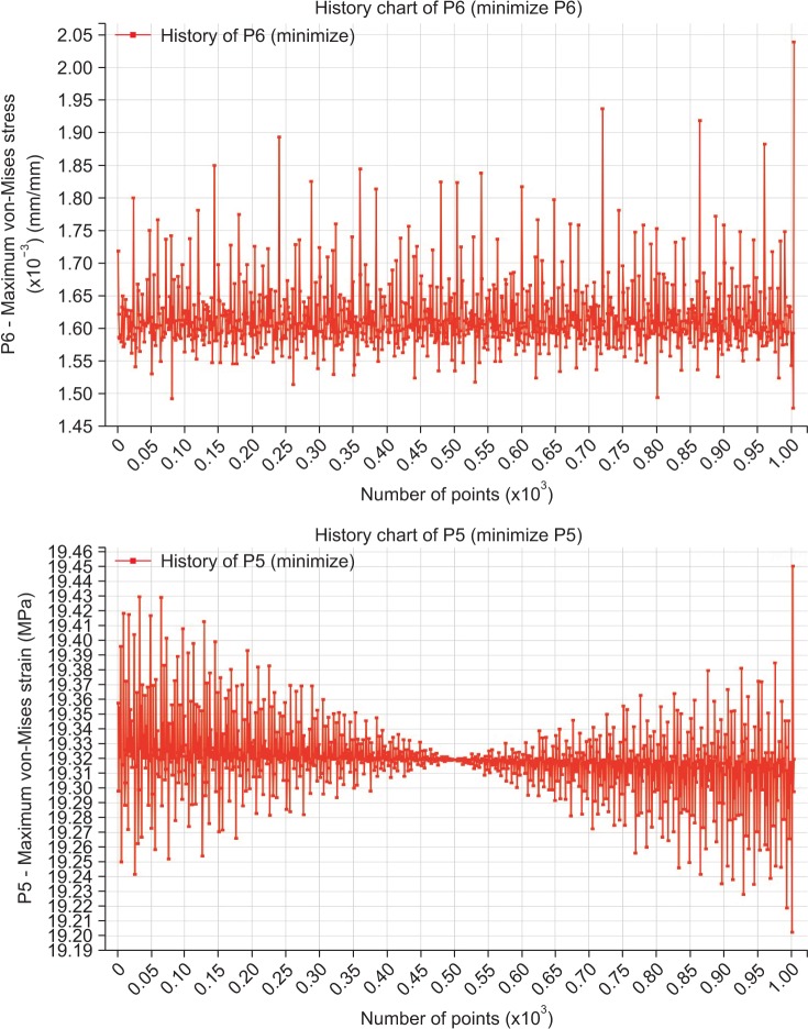
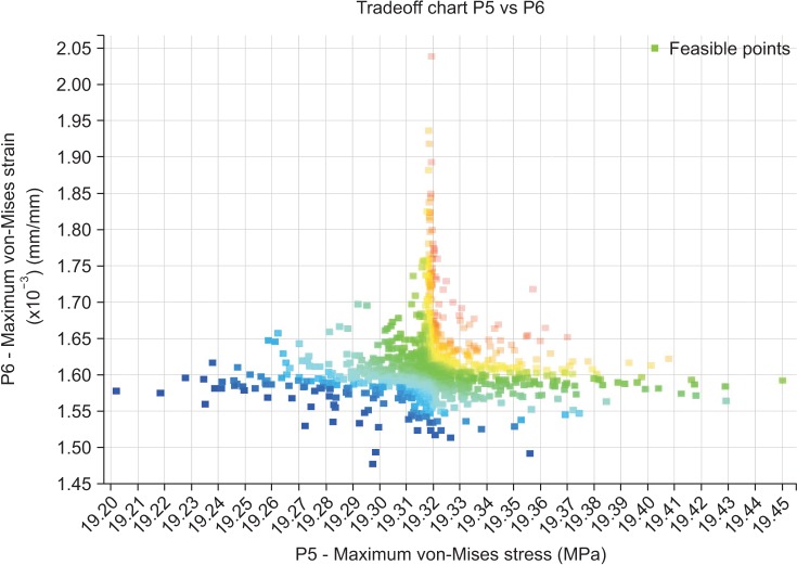
Fig. 4 shows different values of stress and strain in all iterations. The main goal was to minimize both parameters; thus, the green zone was desirable and optimal in this process.
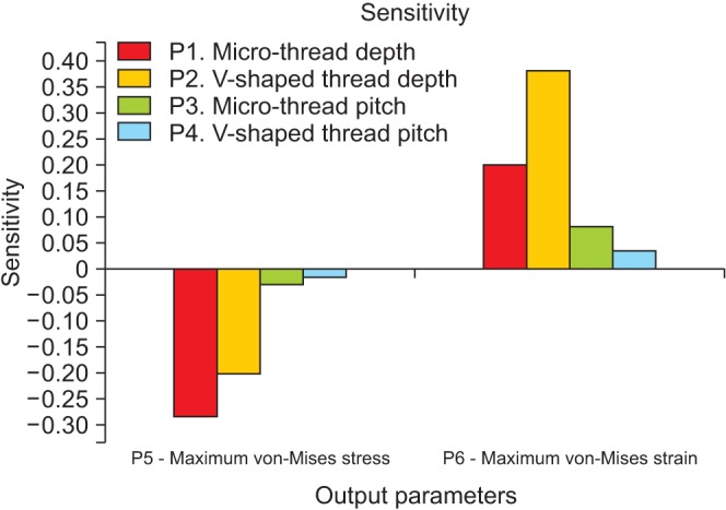
Sensitivity analysis was also performed in this study and indicated the most effective input parameters considering output parameter values. Fig. 5 shows the results obtained in this part of analysis. As shown, depth and pitch of micro-threads had greater effects on equivalent stress and strain.
Go to :
IV. Discussion
Design and analysis of dental implants is an interesting topic for research. Thread-related parameters are of great importance due to their effects on stress and strain distribution. Our previous studies focused on determining the best thread pattern among different screw models, and the optimal implant was chosen based on FEA and was a screw with microthreads in the upper area and V-shaped threads in the rest of the body1011.
In the present study, the main objective was to find the perfect size of the above-mentioned thread pattern. Four critical parameters were considered as input variables, which were depth and pitch of micro-threads and V-shaped threads. Reasonable ranges were defined for these parameters, and the model was solved 1,000 times for different quantities of input parameters in these ranges to find the perfect output parameters. This process took a few hours, and the solutions are shown in Fig. 2. The software produces three candidate points that have the best results based on the given information. The characteristics of these points are presented in Fig. 3 and Table 2 for the purpose of comparison. The optimal answer can be chosen from these candidate points. In this study, candidate point number 1 was chosen due to smaller stress and strain values. Fig. 4 shows the two output parameters. The software was asked to minimize both parameters, so the green zone was acceptable for the purpose of this study.
Design sensitivity analysis plays an important role in all engineering design processes. In this study, this analysis was also considered carefully to have a better understanding of the effectiveness of different design parameters. The results of such analysis help researchers to focus on important parameters. This model showed that micro-thread size was important and has large effects on stress and strain distribution. Micro-threads are designed in the upper area of the implant, which is in contact with cortical bone. This part experiences the most stress, especially at the contact point of first thread with cortical bone. This conclusion had been reached in previous studies1011. In this study, sensitivity analysis proved the importance of the mentioned area, which receives the highest load and needs to be considered carefully in dental implant designs.
There are some limitations as well as simplifications in FEA, which limit the generalization of results to the clinical setting. For example, the force of the tongue and other muscles in the oral cavity is not taken into account in FEA, and abutment is considered to be rigid and fixed, which is not true in a clinical setting. In addition, the micro-movements of the abutment may affect the clinical results long-term. In FEA, loading conditions are not exactly the same as in the clinical situation, since they vary in males and females and in different chewing conditions. Also, loading is considered to be static in this study despite the dynamic nature of applied loads in the clinical setting. Another important factor is the quality of the jawbone, which is not the same in all individuals and may even vary in the same individual in different areas. In the current study, the jawbone was assumed to be isotropic and homogenous in FEA, which is not the case in vivo and may be responsible for the differences in results compared to those obtained in the clinical setting and with other FEA using different bone quality assumptions.
The implant-cortical/cancellous bone interface was completely bonded in the present study, although it was not the same as in clinical conditions. Moreover, absence of some components such as crown, which was not included in the model, may affect stress/strain patterns. In the clinical setting, occlusal forces are applied to a crown; in FEA, they are placed on the abutment. Therefore, FE models cannot provide absolute and realistic values of stress and strain in jawbone/implant systems of an actual model and thus may not be quantitatively validated by a clinical study. However, for a comparative study, such simplifications are reasonable. Future studies may include friction in models as a challenging factor to obtain more realistic results. Changing the angles of the taper and bevel may yield more accurate results and can be evaluated in further studies.
Go to :
V. Conclusion
Based on the results of this study, the optimal dental implant design has micro-threads with 0.307 and 0.286 mm depth and pitch, respectively, in the upper area and V-shaped threads with 0.405 and 0.808 mm depth and pitch in the rest of the body. This model may result in optimal stress distribution and subsequently better osseointegration and greater durability. In addition, it has been concluded that micro-thread parameters have greater effects on stress and strain values, which proves that the upper area in implants is more important than the rest of the body. This conclusion was made based on sensitivity analysis in FEA.
Go to :
 XML Download