

 PDF
PDF ePub
ePub Citation
 Print
Print


I. Introduction
Trauma-induced bony ankylosis that occurs during a growth period can hamper the vertical growth of alveolar bones. This condition results in an open bite that poses aesthetic and functional problems12. A single-tooth dento-osseous osteotomy may be the optimal treatment plan for bony ankylosis23. Here, we introduce a method for performing single-tooth dento-osseous osteotomy with a surgical guide created with computer-aided design/computer-aided manufacturing (CAD/CAM) technologies. This guide design was based on preoperative surgical simulation data.
Go to : 
II. Technical Note
A 19-year-old female patient visited the hospital for treatment of an open bite in the anterior maxilla. She had a history of reduction, caused by trauma-induced avulsion of the left maxillary central incisor. The left maxillary central incisor was affected by bony ankylosis and could not be displaced, even with orthodontic therapy. Thus, we decided to distract it by cutting the left central incisor area and the neighboring bones to induce osteogenesis.
The osteotomy plan was based on a surgical simulation. First, we constructed a three-dimensional (3D) image of the maxillary region, based on a computed tomography (CT) image.(Fig. 1) Then, we performed a simulated dento-osseous segmental osteotomy with three cuts: one between the left and right maxillary central incisors, a second between the left maxillary central incisor and the lateral incisor, and a third cut in the apical region of the left maxillary central incisor. Then, with the CT data of the maxillary bony surface and the cutting data from the surgical simulation, we used Mimics software (version 14.0; Materialise, Leuven, Belgium) to design a surgical guide to fit the maxillary region. The surgical guide was then manufactured from biocompatible materials (VisiJet Crystal; 3D Systems Inc., Rock Hill, SC, USA) with a 3D printer (ProJet 3500 HDMax 3D Printer; 3D Systems Inc.).
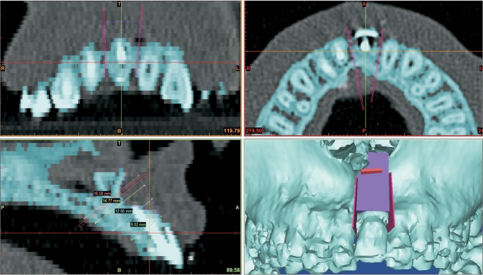 | Fig. 1Surgical simulation and surgical guide for dento-osseous segmental osteotomy of the left maxillary central incisor region (lower right). This three-dimensional reconstructed image of the inside of the mouth shows the proper placement of the surgical guide (purple) and the planned cutting lines (red). Measurement of the cutting depth from the surgical guide surface to the palatal side is shown in the lower left panel.
|
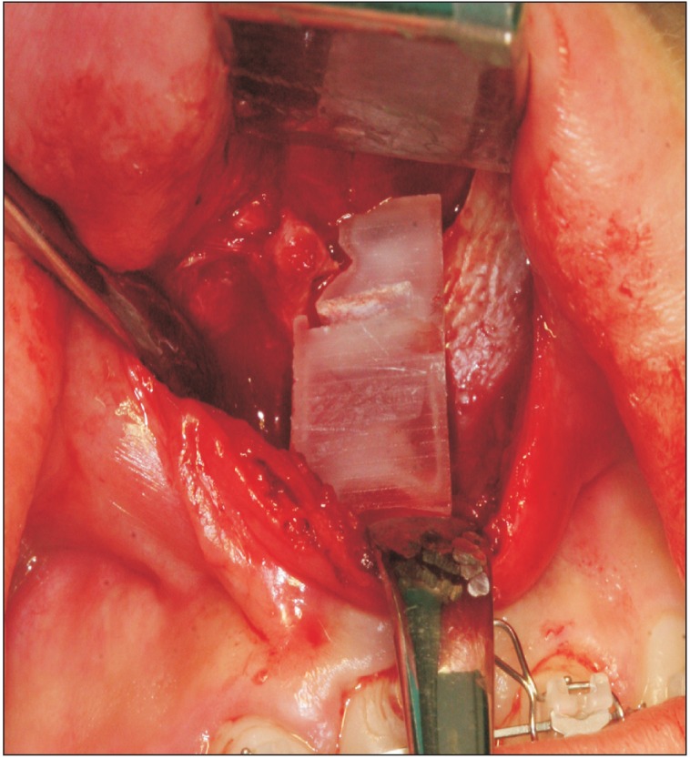
In surgery, a vestibular incision was used to expose the maxillary central incisor bony region. Then, the manufactured surgical guide was placed in the appropriate position. (Fig. 2) After confirming that the guide had been appropriately fitted, the bone was cut with a piezo saw, following the side of the guide. The cutting depth was determined by the lengths of the sections measured during the simulation. (lower left image in Fig. 1) Then, the apical region of the maxillary central incisor was cut with the piezo saw, using a groove in the surgical guide. Similarly, the cutting depth was determined with reference to the distance between the surgical guide and the bone on the maxillary palatal side. Next, the dento-osseous segment that was separated from the maxilla, and blood circulation was confirmed.
Starting six days after the single-tooth dento-osseous segmental osteotomy, the left maxillary central incisor bone segment was distracted by approximately 0.5 mm per day toward the occlusal plane with an orthodontic device. The distraction was performed considering the upper displacement and the axis of the tooth. Seven days after the distraction, we fixed the position with orthodontic brackets. At the eight-week follow-up, there were no signs of gingival recession, and we observed appropriate wound healing with adequate mobility.
This study was approved by the Institutional Review Board of the National Health Insurance Service Hospital (2015-11-007).
Go to :
III. Discussion
Single-tooth dento-osseous segmental osteotomy is a good option when vertical alveolar bone growth is hampered by bony ankylosis234. Distraction of a dento-osseous segment can be performed with an orthodontic device that is either fixed with screws inserted into the osseous segment or with a bracket that is bonded onto the coronal part of the tooth234. However, it may be difficult to determine the cutting section between adjacent teeth, and the procedure may hinder blood circulation to the dento-osseous fragment. In addition, complications such as gingival recession can occur25.
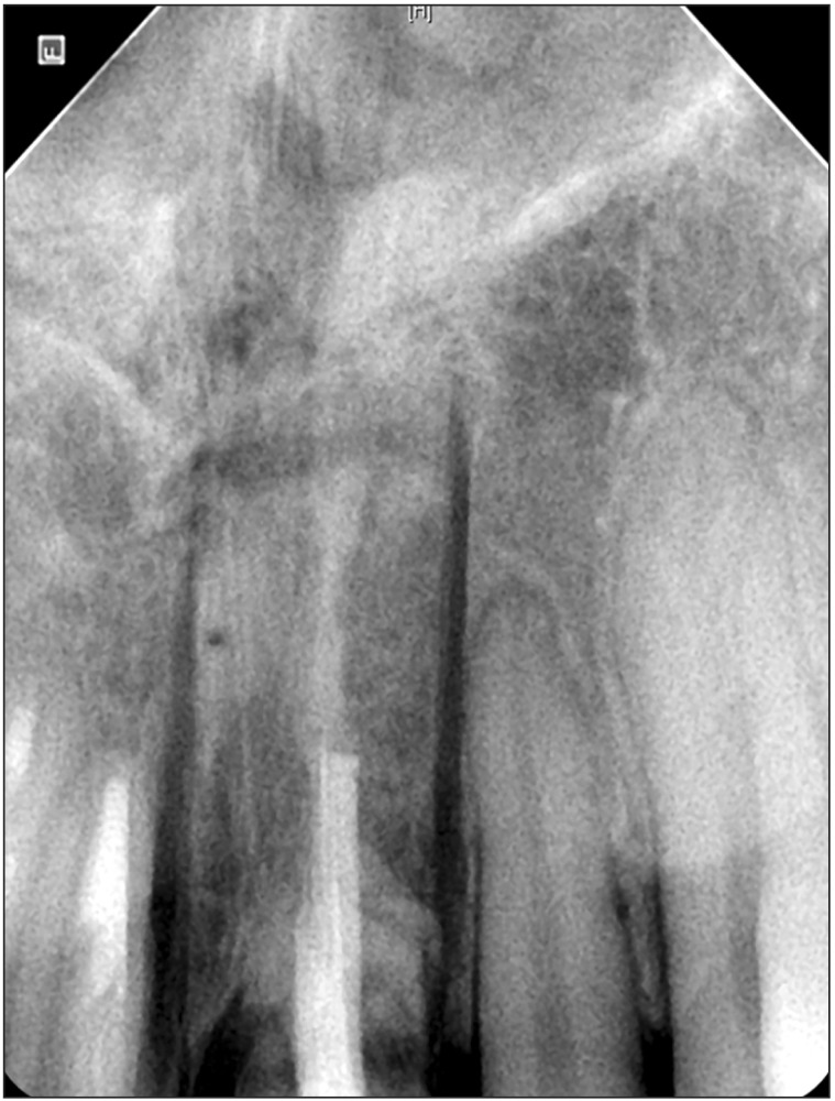
The small size and simple design of the surgical guide described in this study can facilitate the single tooth dentoosseous osteotomy by shortening the duration of surgery and reducing the risk of trauma. Despite its advantages, however, it can damage the surrounding teeth if positioned inappropriately during the operation.(Fig. 3) The surgical guide design must consider the thickness of the cutting saw. In the present case, the bone cuts were placed slightly wider (to the left and right of the right maxillary central incisor) than preoperatively planned; this placement was partly due to the surgical guide design, which required the cutting saw to lean against the side edge of the guide. A better design would be to increase the size of the guide, which would enhance its positional stability, and to employ grooves for all cuts. Under these conditions, the saw could be placed within the grooves during the osteotomy. Postoperative trauma on the maxillary palatal side flaps might also be reduced by calculating the cutting depth based on the distance from the guide's superior edge to the maxillary palatal side, which can be measured in the simulation.
Currently, preoperative surgical simulations confer an array of advantages67. The benefits of more accurate and shorter operations when using CAD/CAM-derived surgical guides are clear. The position and form of the osteotomy line can be adjusted in simulated surgery, minimizing the possibility of dental damage. Moreover, using a cutting guide allows the surgeon to adjust the depth when cutting, leading to a less-invasive and stable osteotomy. The usefulness of surgical guides may also depend on the surgeon's expertise and the type of surgery.
There are several drawbacks to use of a cutting guide. There is a cost associated with the effort, time, and equipment needed to design and manufacture these devices. Even when a surgical guide cannot be designed or used, taking advantage of preoperative simulation surgery to derive relevant measurements can still reduce surgical error during the actual operation. In addition, the costs associated with the design and use of cutting guides will decrease as the associated technologies improve.
Surgical guides can be of most use in complex osteotomy, when it might be difficult to accurately reproduce the results of a surgical simulation in the actual operation room; in these scenarios, a surgical guide can be highly beneficial. We believe that this report will be followed by more thorough research on various designs of surgical guides for use in dento-osseous osteotomy. We expect that further research on the development and assessment of dento-alveolar surgical devices, together with iterative improvements in computing power and software, will expand the possibilities for computer-assisted surgeries. Enhanced navigation and precision robotic surgeries will further increase the power of the now well-established computer-aided treatment field in dentoalveolar surgery.
This report showed that preoperative simulation and the manufacture of a simple surgical guide based on simulation data greatly facilitated successful single-tooth dento-osseous segmental osteotomy.
Go to :
 XML Download