

 PDF
PDF ePub
ePub Citation
 Print
Print


This technique describes the superimposition of three-dimensional (3D) images of dental cast models on computed tomography (CT) images using the surface-based registration (SBR) function of industrial computer-aided design/computer-aided manufacturing (CAD/CAM) software for use in surgical simulation medical software that lacks a defined tool for SBR.
First, a facial CT image, stored as a digital imaging and com munications in medicine (DICOM) file, is imported into the simulation software (e.g., Mimics version 14.0 software; Materialise, Leuven, Belgium) to convert the DICOM format to the stereolithography (STL) format. Any simulation software that has the DICOM-to-STL conversion function can be used.
Impressions of the patient's teeth are used to create a dental model with dental stone. Each dental cast model is scanned with a 3D-light scanner (e.g., Rexcan DS2; Solutionix, Seoul, Korea) to obtain the STL data. Then, both the CT and the dental cast STL files are imported into commercial CAD/CAM software (e.g., Rapidform XOV2; INUS Technology, Seoul, Korea), which has a SBR function for overlapping images in a user-defined surface.
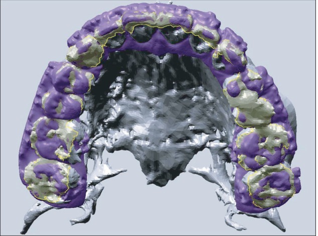
Next, the occlusal surface area is defined. The STLs of the maxillary and mandibular scans of the dental cast are superimposed onto the STL of the CT with the SBR function.(Fig. 1) Deciding which image to move is an important step. Here, the dental cast image must be moved to match the CT image, as the surgical simulation software uses the CT data. Thus, the STL of the dental casts will have positional information relative to the CT image, and every point on the STL has 3D coordinates. The displaced STL of the dental casts is then exported from the CAD software and imported into the surgical simulation software without any other registration procedure.
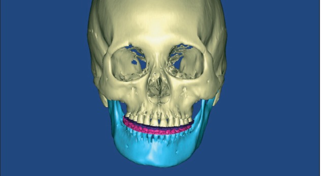
Finally, although the medical simulation software lacks a SBR function tool, the digital dental casts can be superimposed onto the CT images based on the SBR information.(Fig. 2)
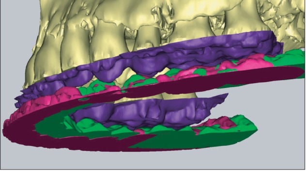
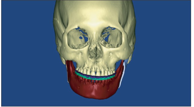
Additionally, to obtain necessary positional information on the mandible with respect to the position of the maxilla during the surgical simulation, the cast model can be fixed in the planned postoperative occlusion state and scanned with the 3D-scanner. Then, the STL of the dental cast must be registered to the coordinates of the CT maxillary occlusal surface with SBR.(Fig. 3) After that, the CT image of the mandible can be superimposed onto the scanned mandible cast image in the planned occlusion state1-3. The displaced STL of the mandible is exported from the CAD/CAM software and imported into the surgical simulation software without any other registration procedure.(Fig. 4) This simulation is used only for mandibular surgery, according to a planned postoperative occlusion in orthognathic surgery.
For a simulation of bimaxillary orthognathic surgery, the surgeon can move both the maxilla and mandible simultaneously, in the planned occlusion state, with the surgical simulation software.(Fig. 5) After the surgical simulation, a stereolithographic surgical guide can also be manufactured with the simulated dental cast data.
This technique has the merits of using the various registra-tion functions of industrial CAD/CAM software in addition to the analysis, diagnosis, and surgical simulation functions of medical software. Furthermore, this technique may be helpful in imaging research using STL and radiologic images.

 XML Download