

 PDF
PDF ePub
ePub Citation
 Print
Print


Introduction
Skeletal open bite is associated with unfavorable craniofacial growth patterns, such as posterior or clockwise rotation of the mandible and excessive vertical growth of the craniofacial skeleton. In non-growing patients, orthognathic surgery with orthodontic treatment may be required to correct a severe vertical skeletal discrepancy. In some mild skeletal open bite cases, conventional orthodontic treatment can be utilized to camouflage the vertical skeletal discrepancy. Posterior tooth intrusion may cause counterclockwise rotation of the mandible. Temporary anchorage devices, such as miniplates or miniscrew implants, play important roles in skeletal anchorage during maxillary and mandibular posterior tooth intrusion.1
Miniscrew implants have been widely used to achieve absolute anchorage because they are easier to place, involve less trauma during placement, cost less, and are smaller than other temporary anchorage devices. The goals of miniscrew implant placement are effective biomechanics for desired tooth movement, good retention, and stability of the miniscrew implants without damaging vital anatomical structures. The miniscrew implant size, length, and placement site depend on the appliance design, biomechanics, important anatomical structures, and the quality and quantity of surrounding bone.23
Moon et al.4 reported significantly less success in inter-radicular miniscrew implants in the buccal maxillary region in patients with an open vertical skeletal configuration, and suggested that this reduction was associated with a high Frankfort-mandibular plane angle and a low upper gonial angle. Some studies56 have found thinner and less dense dento-alveolar bone in patients with open vertical skeletal configurations than in those with deep vertical skeletal configurations. Therefore, the risk of miniscrew implant failure may increase after miniscrew implant placement in the maxillary and mandibular alveolar bone in patients with an open vertical skeletal configuration. Some studies78 have suggested the palate as an alternative region for miniscrew implant placement due to the dense palatal bone, sufficient palatal cortical bone thickness, and the presence of few vital anatomical structures.
Accordingly, this study aimed to compare the palatal bone thickness in class I Thai patients exhibiting normal overbite and a normal vertical skeletal configuration to that in class I Thai patients exhibiting anterior open bite and an open vertical skeletal configuration, using conebeam computed tomography (CBCT).
Materials and Methods
Subjects
This retrospective study was approved by the Human Experimentation Committee, Faculty of Dentistry, Chiang Mai University (NO.39/2559). Informed consent was obtained from all patients before the CBCT images were taken. The subjects were Thai orthodontic patients at the Faculty of Dentistry, Chiang Mai University, who required pretreatment CBCT images for the placement of a miniscrew implant as skeletal anchorage and met the following inclusion criteria: 1) age from 15 to 30 years; 2) full eruption of the permanent dentition (except for the third molars); 3) no history of previous orthodontic treatment; 4) no evidence of craniofacial malformations; 5) no history of bone-altering medications or diseases; 6) absence of torus palatinus; 7) a class I malocclusion with class I sagittal skeletal relationship (A point-nasion-B point angle, =2°±2°)
The CBCT images of the 30 patients were taken using a ProMax 3D (Planmeca Oy, Helsinki, Finland) machine at 84 kVp and 10 mA, with a field of view of 8 cm×8 cm and a voxel size of 0.16 mm. Each patient was positioned with the occlusal plane horizontal. The CBCT images were divided into 2 groups. The normal-bite group (N=15) included patients exhibiting normal overbite (overbite=0–2.0 mm) and a normal vertical skeletal configuration (5 males and 10 females; age, 20.5±3.8 years; range, 15.0–29.1 years), while the open-bite group (N=15) included patients exhibiting anterior open bite (overbite<0 mm) and an open vertical skeletal configuration (3 males and 12 females; age, 19.1±3.2 years; range, 15.0–25.6 years). The vertical skeletal configuration was determined according to 6 cephalometric measurements: 1) the angle of the sella-nasion line (SN) to the gonion-gnathion line (GoGn); 2) the angle of SN to the palatal plane (PP) angle; 3) the PP-GoGn angle; 4) the gonial angle; 5) the ratio of upper to lower face height; and 6) the ratio of posterior to anterior face height. A patient was considered to have an open vertical skeletal configuration if the configuration was confirmed by 3 or more cephalometric measurements. A patient was considered to have a normal vertical skeletal configuration if 4 or more cephalometric measurements indicated a normal vertical skeletal configuration.
Measurement of palatal bone thickness
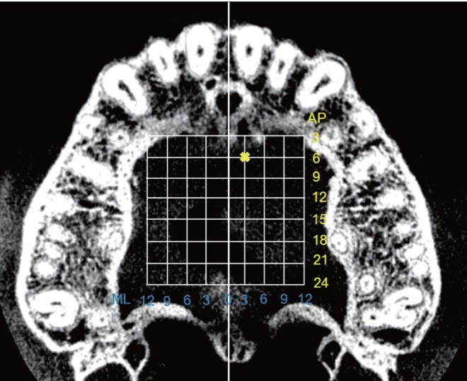
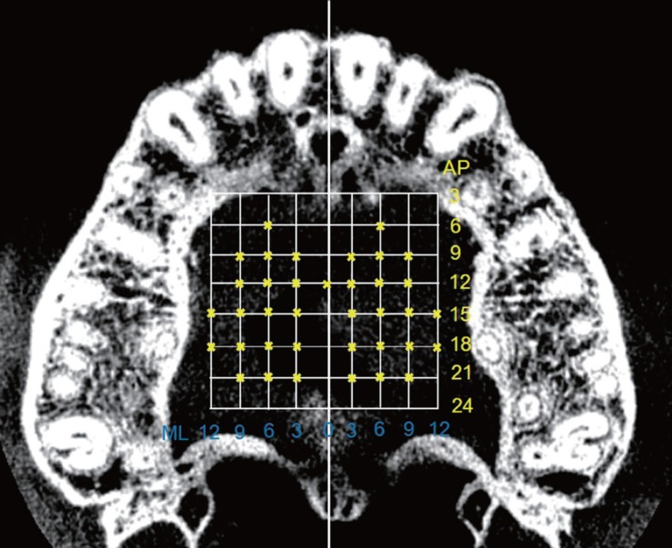
Using the Planmeca Romexis Viewer 2.3.1.R program (Planmeca Oy, Helsinki, Finland), a line joining the middle of the distal bony margin of the incisive foramen and the posterior nasal spine (PNS) was oriented to the midsagittal plane. In the midsagittal view, the horizontal reference plane was oriented to pass through the middle of the distal bony margins of the incisive foramen and the PNS (Fig. 1).9101112 The palatal bone thickness was measured perpendicularly to this horizontal reference plane from the outer border of the palatal cortical bone to the outer border of the cortical bone of the nasal floor, maxillary sinus floor, or incisive canal floor. In the sagittal view, the palatal bone thickness was measured at 3.0-mm intervals posteriorly from the middle of the distal bony margin of the incisive foramen to the PNS (Fig. 1). In each frontal view, the palatal bone thickness was measured at 3.0-mm intervals laterally from the midsagittal reference plane (inclusive) on both right and left sides (Fig. 2), producing a grid pattern of measurements (Fig. 3). To test intra-examiner reliability, 10 randomly selected CBCT images were re-measured by the same examiner after a 4-week interval. In addition, 10 randomly selected CBCT images were re-measured by an oral and maxillofacial radiologist.
Each measurement site was named according to the anteroposterior (AP) and the mediolateral (ML) intervals on both the right and left sides. For example, the measurement site marked x in Figure 3 would be named “Left AP6/ML3.”
Statistical analysis
Data were analyzed using SPSS version 17.0 (SPSS Inc., Chicago, IL USA). Means and standard deviations of the palatal bone thickness of the normal-bite and open-bite groups were measured and compared using the independent t-test. Results were considered statistically significant at P<.05.
Results
The intra-examiner and inter-examiner reliability test for the measurements of palatal bone thickness showed high intraclass correlations (r=0.985 for the intra-examiner reliability test, r=0.884 for the inter-examiner reliability test), suggesting that the measurements were highly reliable. The palatal bone thickness in both groups was normally distributed, and no statistically significant difference was found between the left and right sides. Therefore, the measurements from both sides were pooled for statistical analysis.
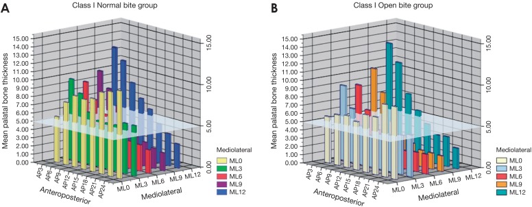
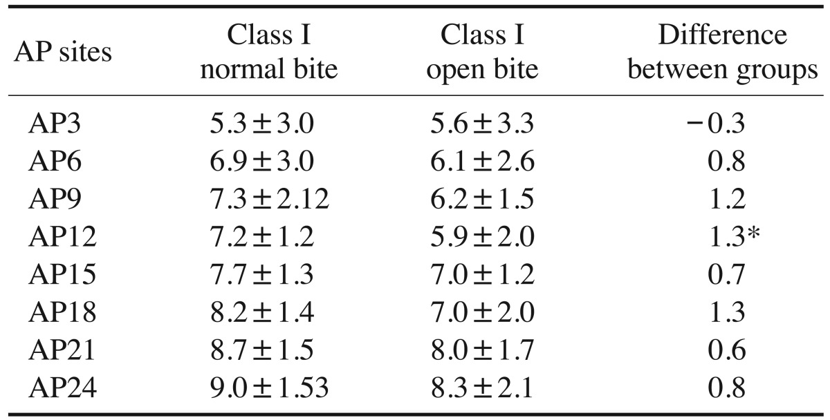
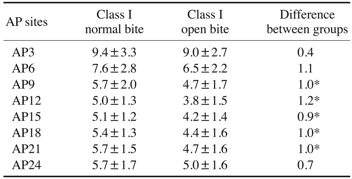
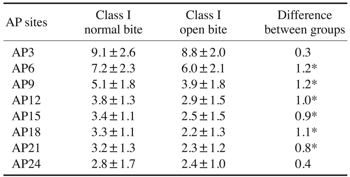
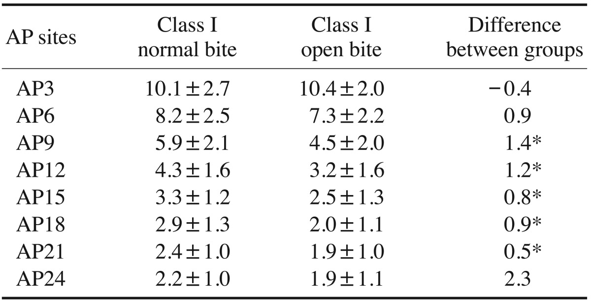
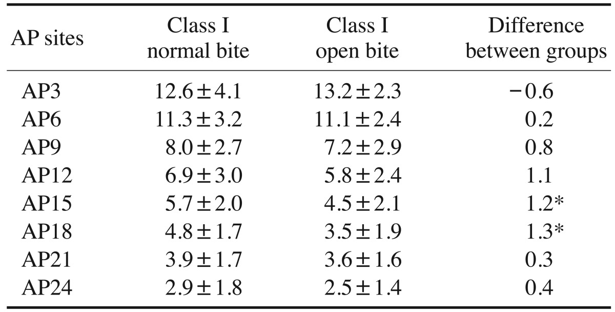
The means, standard deviations, and comparisons of the palatal bone thickness of the normal-bite and openbite groups are shown in Tables 1,2,3,4,5, respectively. Combined plots of the palatal bone thickness of both groups are shown in Figure 4. The palatal bone thickness in the normal bite group ranged from 2.2±1.0 mm (at the AP24/ML9 site) to 12.6±4.1 mm (at the AP3/ML12 site). The palatal bone thickness was at least 5.0 mm at all AP sites along both the ML0 and ML3 sections, but only at the AP3-AP9 sites along the ML6 and ML9 sections, and at the AP3-AP15 sites along the ML12 section. The palatal bone thickness in the open bite group ranged from 1.9±1.1 mm (at the AP24/ML9 site) to 13.2±2.3 mm (at the AP3/ML12 site). The palatal bone thickness was at least 5.0 mm at all AP sites along the ML0 section, but only at the AP3–AP6 sites along the ML3, ML6, and ML9 sections, and at the AP3–AP12 sites along the ML12 section. The palatal bone thickness at almost all AP/ML sites in the open-bite group was lower than the corresponding value in the normal bite group. Significant differences were found at the AP12 site along the ML0 section, at the AP9–AP21 sites along the ML3 section, at the AP6–AP21 sites along the ML6 section, at the AP9–AP21 sites along the ML9 section, and at the AP15–AP18 sites along the ML12 section (P<.05) (Fig. 5).
Discussion
Several previous studies13141516 have attempted to investigate palatal bone thickness by various direct and radiological measurements. In our investigation, palatal bone thickness was evaluated using CBCT. Three-dimensional imaging with high resolution provides accurate and reliable information about the osseous structure and surrounding vital structures.12 This information is beneficial during orthodontic treatment for determining adequate miniscrew implant length and identifying miniscrew implant placement sites with sufficient available bone, especially in the palatal areas of patients with class I normal bite and those with class I open bite.
Information pertaining to palatal bone thickness supports the selection of the ideal miniscrew implant placement sites and miniscrew implant length to ensure adequate retention and to avoid damaging vital structures. Winsauer et al.17 have suggested that at least 5.0 mm of bony support is needed to resist rotational forces and dynamic loads, contributing to the stability of miniscrew implants. For the palatal bone thickness measurements, our investigation determined that the end points of measurement at the outer borders of the cortical bone of the surrounding vital structures were located at the nasal floor, maxillary sinus floor, or incisive canal wall. The palatal bone thickness was measured perpendicularly to the reference plane, as recommended by several studies.910111218 The horizontal reference plane permitted reproducible measurement intervals, and was parallel to the palatal bone surface, except for the posterior and transverse end points. Measurements made perpendicularly to the palatal bone surface cannot provide accurate or reproducible intervals, because the palatal arc is not a straight line.81118 According to our findings, miniscrew implant placement perpendicular to the reference plane might be limited in some areas due to clinical inaccessibility.
Our investigation showed that the palatal bone thickness in the normal-bite and the open-bite groups had similar patterns, although they were not equal (Fig. 6). Differences in the palatal bone thickness between the 2 groups might be explained by masticatory muscle function, bite force, and soft tissue function, which influence skeletal morphology. The mechanostat hypothesis of Frost19 proposes that the form and mass of bone is influenced by a range of strains. Some studies2021 have shown an association between increased facial divergence and decreased muscle function. Furthermore, other studies5620 have reported relationships between an open vertical skeletal configuration and reduced thickness and density of alveolar bone and of alveolar cortical bone due to lower masticatory function and bite force. However, bony adaptation has been found not only in alveolar bone, but also in other facial bones to which force is dissipated.21 In animal experiments,2223 relationships between high strains from masticatory forces and a thickened palate have been reported. However, the relationships between masticatory function and bite force and palatal bone thickness in humans are still controversial.2425 Johari et al.26 reported reduced palatal cortical bone thickness in some palatal areas in patients with an open vertical skeletal configuration. Further studies should focus on the association between palatal bone thickness and both masticatory muscle function and bite force in the hyperdivergent facial type.
According to our investigation, in the normal bite group, when palatal miniscrew implant placement is required in the anterior region of the palate (3.0–9.0 mm posteriorly from the incisive foramen), the paramedian area would be the optimal site. This finding agrees with those of other studies that found sufficient palatal bone thickness at the anterior paramedian palate.8910 When palatal miniscrew implant placement is required in the middle and posterior regions of the palate (12.0–24.0 mm posteriorly from the incisive foramen), the optimal sites would be along the ML0 or ML3 sections. Additional bone height along the ML0 section is provided by the nasal crest.111627 However, miniscrew implants longer than 6.0 mm are not recommended at the AP3 to AP6 sites along the ML0 section (or the midpalatal plane) to avoid nasopalatine nerve injury.9101118 According to our investigation, paramedian areas more than 3.0 mm lateral from the midpalatal plane and 9.0 mm posterior from the incisive foramen should be avoided due to the potential for poor miniscrew implant retention and the risk of nasal perforation. Contrastingly, other CBCT-based investigations891011 have recommended not placing miniscrew implants in the paramedian areas of the middle or posterior palate more than 1 mm lateral to the midpalatal plane, due to the lack of sufficient palatal bone. The discrepancy in the results of this and other studies may be due to variations in palatal bone thickness, differences in measurement methods, or ethnically specific differences. Moreover, in the open-bite group, the suggested miniscrew implant placement sites in our investigation included all AP sites along the midpalatal plane or 3.0–6.0 mm posterior from the incisive foramen along the other ML sections. However, there may be differences in the palatal bone thickness in patients of different genders and ages. Such differences should be further investigated.
In summary, the palatal bone thickness at almost all AP/ML sites in the open-bite group was significantly lower than the corresponding values in the normal-bite group. Class I malocclusion with an open vertical skeletal configuration might affect palatal bone thickness, so the placement of temporary anchorage devices or miniscrew implants in the palatal areas in such patients should be performed with caution.


 XML Download