

 PDF
PDF ePub
ePub Citation
 Print
Print


Introduction
Radiographs are an important method of diagnosing and monitoring oral diseases, dentofacial development, and the progress or prognosis of therapy.1 Panoramic radiography is recommended for patients in several age ranges: children with transitional dentition (after eruption of the first permanent tooth); adolescents with permanent dentition (prior to the eruption of the third molars); and adults who are dentate or partially edentulous. Panoramic radiographs are also recommended in new patients being evaluated for oral diseases and in patients undergoing follow-up, based on clinical signs, symptoms, and treatment plans.1 Intraoral radiographs are more accurate than panoramic radiographs; however, panoramic examinations may be advantageous because they involve a reduced radiation dosage, cost less, and allow a larger area to be imaged. Thus, although these issues have been addressed in prior studies, it is important that dentists understand the mechanisms associated with the formation of real and ghost images in panoramic radiographs.
The panoramic radiograph technique is based on the principle of computed tomography, since both techniques involve synchronized rotation between an X-ray source and an image receptor around the patient's head that remains stationary.2 This is a radiological technique that is relatively simple and is commonly used in all dental specialties, 34 since patients have shown a good tolerance to this technique, it is fast and comfortable, and, most importantly, it includes the entire maxillomandibular structure (dental arches, temporomandibular joint, and associated structures) in a single film.456 It is used in a broad range of clinical settings, including the evaluation of deciduous and permanent teeth; orthodontic evaluations; the evaluation of bone lesions, erupted teeth, periodontal bone supports, third molars, lesions in the maxillary sinus, and fractures of the mandible; and evaluations of foreign bodies and the loss of bone mineral density (osteopenia and osteoporosis); among others.4678 However, this technique also presents certain disadvantages, such as the overlap of the images of certain anatomical structures, the amplification and reduction of images (geometric distortion), and the production of ghost images.356910
Ghost images, or artifacts, are created by anatomical structures or objects that are located outside of the zone of focus or image layer but have a sufficient density to attenuate the X-ray beams, in turn producing distorted radiographic images.2 Although panoramic radiographs play a crucial role in diagnosis, these ghost images complicate the use of panoramic radiographs, since they may closely resemble the lesions themselves, be confounded with dental structures in inappropriate locations, or mask anomalies by obstructing the view of subjacent anatomical structures.4
Panoramic radiographs of a patient with earrings inserted in his or her earlobe are one of the most common examples of how ghost images of non-anatomic origin may be formed.2 In such cases, one can observe images of the earrings in the molar region, the coronoid process, the mandibular notch, and/or the mandibular condyle, resembling an impacted tooth or a cyst, among other abnormalities. It is therefore important to understand the appearance of anatomical structures and their variations in panoramic radiographs,4 with the additional challenge of identifying structures that fall outside of the standards of normality in order to make correct and coherent diagnoses.
Since many patients have piercings or other metal objects in their facial region, and as these objects can impair the quality of the panoramic radiograph image and its interpretation, it is important to understand the errors and artifacts that accompany this radiological technique. Therefore, the aim of the present study was to present a study of the formation of ghost images in panoramic radiographs caused by metal objects in different regions of the skull, as well as to report a clinical case, in an attempt to aid dentists in understanding the mechanisms associated with the formation of real and ghost images in panoramic radiographs.
Materials and Methods
After having received approval for the present study from our institution's Ethics Committee (CAE: 45441815.4.0000.5137), we conducted this study using a macerated adult skull placed in a Kodak 9000C three-dimensional panoramic device (Eastman Kodak Company, Rochester, New York, USA). The skull was positioned in the X-ray device according to standard procedures, with its sagittal plane placed in the center of the zone of focus of the X-ray unit and perpendicular to the horizontal plane and the Frankfurt plane parallel to the horizontal plane. According to the bitewing of the device, the top teeth were arranged to place the dental arches in the zone of focus or image layer.
A round metal object was attached in various areas of the skull to assess the formation of real and ghost images (the region around tooth 46, the upper region of the ear, the anterior nasal spine, the nasal wing, the lateral pole of the temporomandibular joint, the region around tooth 18, the mandibular angle, the earlobe, the hyoid bone, and the dorsum of the tongue). One image was taken with no metal object, which was defined as the control radiograph. The radiographs were taken using the following exposure factors: 60 kV, 2.0 mA, and 14.3 s of exposure.
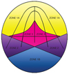
The present study mapped the maxillomandibular areas according to the diagram proposed by Reuter et al.,11 who demonstrated the formation of one, two, or three similar images after the strategic positioning of a metal object in different anatomic structures of the face. Reuter et al.11 referred to the zones where the test object was portrayed once as zone 1A and zone 1B, the zone where the test object was portrayed twice as zone 2, and the zone where the test object was portrayed three times as zone 3 (Fig. 1). In the areas corresponding to zone 1A, which comprises the anterior regions of the mandible and the maxilla, the formation of one single real image occurs. In zone 1B, which includes the most posterior portion of the zone of focus or image layer (i.e., the regions of the occipital bone and the foramen magnum), the production of a single ghost image occurs. The mandibular ramus and angle, the mandibular condyles, the hard palate, and the earlobes are located in the areas corresponding to zone 2, where two images are produced: one ghost image and one real image. In zone 3, comprising the spine and hyoid bone, the formation of a triple image can be observed, including two real images lateral to the film and one ghost image in the center of the film.
In this study, the images obtained from the skull were examined directly in the Kodak Dental Imaging Software (Kodak Dental Systems, Rochester, NY, USA) by two trained oral radiologists, one with ten years of experience and the other with eight years of experience. They used a computer with a GeForce 9500 GT graphics card (Nvidia Corporation Santa Clara, CA, USA), and an LED LG Flatron E2241 monitor (LG Electronics, Seoul, Korea), with a resolution of 1920×1080 pixels and the brightness and contrast levels of the monitor set to the default configuration. The analysis of the images was performed following the schematic design of zones 1A, 1B, 2, and 3. Disagreements were resolved by discussion, and a final consensus was reached.
In order to exemplify the importance of the anatomic and technical knowledge of the formation of panoramic radiographic images, we also report the clinical case of a 24-year-old male patient referred to the radiology clinic to undergo dental exams necessary for orthodontic treatment. Panoramic and lateral cephalometric radiographs were taken using the Orthopantomograph® OP 100 (Instrumentarium Imaging, Tuusula, Finland). For the panoramic radiograph, the X-ray tube was operated with settings of 57 kVp, 3.2 mA, and an exposure time of 17.6 s. For the lateral cephalometric radiograph, the X-ray tube was operated with settings of 80 kVp, 10 mA, and an exposure time of 0.7 s. After radiographic exposure, all films were processed in a Macrotec MX-2 automatic processor (Macrotec, São Paulo, Brazil) with Picker RP type-S processing chemistry (Eastman Kodak Company, Rochester, NY, USA).
Results
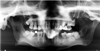
First, a panoramic radiograph was taken of the macerated skull with a metal sphere attached in the region where tooth 46 was missing. This region was located within the focal plane, corresponding to the formation of images in zone 1A. The result was a single real image of the metal sphere (Fig. 2).
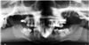
Figure 3 presents a panoramic radiograph taken with a metal sphere that was attached to the crown of tooth 18. This region is located in the focal plane but corresponds to image formation in zone 2. The result was the production of a real image in the region of the crown of tooth 18 (ipsilateral) and a ghost image on the opposite side (contralateral). The ghost image was located at a higher position and was sharper.
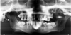
Figure 4 shows another example of a panoramic radiograph taken with a metal sphere located in zone 2. In this case, the metal sphere was attached in the region of the right earlobe, producing a real ipsilateral image and a distorted contralateral ghost image.
In the last panoramic radiograph, the metal sphere was attached in the region of the hyoid bone (Fig. 5). This region corresponds to image formation in zone 3. Thus, three images were formed, with two real and bilateral images projected in the region of the right and left mandibular angle and one ghost image in the center of the film, overlapping the region of the inferior incisors.
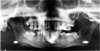
In this case report, the panoramic radiograph presented a radiopaque image overlapping the roots of the molars, premolars, and canines, located in the upper right hemiarch (Fig. 6A). The lateral cephalometric radiograph was analyzed to evaluate the existence of a metal object that could explain the formation of the radiopaque band observed in the panoramic radiograph (Fig. 6B).
Discussion
This study demonstrated the formation of real and ghost images in panoramic radiographs through the placement of metallic objects in different maxillomandibular regions of a macerated adult skull. The images were analyzed using the schematic design of zones where the test object was portrayed once (zone 1A and 1B), twice (zone 2), and three times (zone 3).
Panoramic radiographs may contain single or double real images, as well as ghost images. A real image is formed when the object is located between the rotation center of the X-ray beam and the image receptor, and the image is taken with high definition and sharpness when the object is near the central layer of the zone of focus (Fig. 7).1213 The central ray of the X-ray beam must also be perpendicular to the object and image detector.14 The shape of the panoramic radiograph zone of focus or image layer is similar to that of the dental arch. Figure 2 shows the formation of a single real image in a panoramic radiograph taken with one metal sphere attached in the region where tooth 46 was missing (zone 1A).
A ghost image occurs when the object or anatomic structure is located between the X-ray source and the center of rotation, and has a density that is sufficient to attenuate the X-ray beams.212 This image subsequently presents the same morphology as the object, but with distortion, and appears on the opposite side and at a higher point than the corresponding real object. The image appears in a vertically expanded form. but may or may not be expanded horizontally.10 The ghost image also contains a corresponding real image, which may or may not be visible in the panoramic radiograph.12 Figures 3 and 4, as well as the case report, illustrate the formation of a real ipsilateral image and a distorted contralateral ghost image in panoramic radiographs with a metal object located in zone 2.
A double image consists of a pair of real images. The double image is formed when an object or anatomic structure is located between the center of rotation of the X-ray beams and the image receptor, but is intercepted twice during the exposure cycle.212 The distance of the object to the image receptor is the same in both instances in which the object is exposed.2 The double images are as sharp as the real images.211 Double images are caused by objects or anatomic structures that are located in the midline. Figure 5 demonstrates the formation of a double image caused by a metal sphere placed in the region of the hyoid bone (zone 3). This figure shows two real bilateral images projected upon the mandibular angle. Another clinical example is the cervical spine, from which a real image is portrayed bilaterally at the extreme sides of the radiograph.12
Triple images can consist of two lateral images and a central ghost, as in case of the cervical spine and hyoid bone.11 In this situation, a real image is portrayed bilaterally at the extreme sides of the radiograph, and the central image is a ghost.1112 Figure 5 exemplifies the formation of a triple image caused by the placement of a metal sphere in the region of the hyoid bone (zone 3).
In this case report, the panoramic radiograph presented a radiopaque image located in the upper right hemiarch. Also observed was a voluminous metal restoration in the occlusal region of tooth 28. The lateral cephalometric radiograph showed no metal object in the upper right hemiarch. Therefore, it was confirmed that the radiopaque image formed in the region of the maxilla on the right side of the panoramic radiograph was in fact a ghost image caused by the restoration of the amalgam present in the maxillary left third molar. The metal restoration was located in zone 2 and produced an ipsilateral real image (restoration in tooth 28) and a distorted contralateral ghost image (radiopaque band).
In conclusion, knowledge of the principles of the formation of ghost images in panoramic radiographs, as well as of normal anatomy, prevents incorrect diagnoses that could result in inappropriate prognoses and treatment plans. It is recommended that, whenever possible, all metal objects should be removed from the head and neck region in order to prevent the formation of ghost images created by these objects.


 XML Download