

 PDF
PDF ePub
ePub Citation
 Print
Print


Introduction
In recent years, interest in accurate orthodontic treatment planning using three-dimensional imaging technology has increased.12 The initial three-dimensional computed tomography (CT) techniques, single-detector CT and multi-detector CT, exposed patients to high doses of radiation.345678 Recently, the introduction of cone-beam computed tomography (CBCT) has provided an alternative imaging modality with higher resolution, lower cost, and lower radiation exposure, which has further fueled research into three-dimensional image analysis.1910111213 However, since CBCT images are obtained when the patient is in a sitting position with their head supported by an unreliable head-holding apparatus, unlike traditional forms of CT, it is difficult to replicate head positions in CBCT, potentially hindering accurate comparisons of the results of orthodontic treatment or surgery. Few studies have evaluated the potential effects of low repeatability in images due to variations in head position.1415
With recent increases in CBCT usage, it has become more common to utilize image analysis programs to process the large amounts of image data created. Some programs provide the ability to adjust the reference plane typically used in CBCT, and this function can be used to compensate for possible image discrepancies when comparing images with different head positions.161718 Studies exploring image analysis functionality have reported no discrepancies in length or angle when various head positions were compared to normal-position images.1314161921 However, while image length and angle may not vary according to head positions, coordinates may do so. No previous studies have investigated discrepancies in coordinates. This study aimed to investigate the effects of various head positions on three-dimensional image coordinates and in turn on orthodontic landmarks using a three-dimensional image analysis program.
Materials and Methods
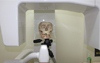
One dry skull was used in this study. In order to simulate the anatomic relationship of the temporomandibular area, base plate wax 1.0 mm in thickness was used to connect the temporal fossa and condylar process. The dry skull was then placed on a tripod for angle adjustment (Fig. 1). Reference coordinates to use in the image analysis program for superimposition were marked at 3 places on the dry skull using gutta percha.
Three planes from the normal position of the dry skull were chosen as references to use when varying head positions. In the study of Togashi et al.,15 3 reference planes were defined: the horizontal plane from the left porion to the right orbitale; the sagittal plane crossing the horizontal plane, nasion, and basion; and the longitudinal plane including the right and left porion and crossing the horizontal plane perpendicularly. After the normal position was established, the position of the dry skull was changed through leftward tilting, leftward rotation, extension, and flexion, all in increments of 5° (Fig. 2).
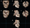
CBCT images were acquired using a RayScan Symphony ® apparatus (Ray Co., Hwaseong, Korea) in the Department of Oral and Maxillofacial Radiology, Yonsei University Dental Hospital. The imaging conditions were a tube voltage of 90 kVp, tube current of 10 mA, exposure duration of 19.5 s, and field of view (FOV) of 14 cm×14 cm. Axial images of 0.38 mm in thickness were reconstructed into three-dimensional images using OnDemand 3D™ (CyberMed Inc., Seoul, Korea) (Fig. 3).
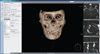
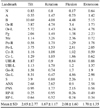
Landmarks conventionally used in orthodontic diagnosis or oral surgery were employed (Table 1).202122 Within a span of a week and in two stages, a dentist with OnDemand 3D™ experience took the multiplanar reconstruction of the normal-position and varied-position images, established 20 landmarks, and computed the three-dimensional coordinates (Fig. 4).
The 3D Ceph module of OnDemand 3D™ was used to establish the 3 landmarks fixed with gutta percha to enable the automatic reorientation of the 20 coordinates for superimposition.13 This process used the axial plane created by the 3 spots fixed with gutta percha as a platform where the perpendicular sagittal and coronal planes could be established. The computed coordinates obtained in this manner were compared to the post-reorientation coordinates.
In order to evaluate intraobserver agreement, intraclass coefficients were calculated. Agreement in coordinates was compared between the normal-position image and the four varied-position images using the paired t-test for identical landmarks, and p-values <0.05 were considered to indicate statistical significance. Discrepancies in the coordinates in each landmark among the images were measured as distances. One-way analysis of variance was used to analyze these distances, and Tukey's post-hoc analysis was employed. The data were analyzed using SPSS version 23.0 (IBM Corp., Armonk, NY, USA).
Results
The landmark coordinates were measured twice and analyzed to determine the intraclass coefficient and showed Cohen's kappa values greater than 0.8.
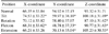
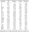
The X, Y, and Z coordinates of the normal-position landmarks and the varied-position landmarks are shown in Table 2. Statistically significant differences were associated with five-degree tilting and flexion in the X coordinates, five-degree tilting, flexion, and extension in the Y coordinates, and all of the altered positions in the Z coordinates. The distances between the normal-position coordinates and the corresponding coordinates in the varied-position images were compared to determine the degree of error between the coordinates, and statistically significant differences were found (Table 3). The mean and standard deviation of the distances were 13.17±3.98 mm for tilting, 15.18±5.41 mm for rotation, 7.91±3.11 mm for flexion, and 22.59±5.72 mm for extension. The five-degree flexion image showed the shortest distance, whereas the five-degree extension image showed the greatest distance. In the left-rotation images, the distances obtained for all the right-side landmarks, such as Or, Po, Co, UIE, Go and RP, were longer than the distances obtained for the left-side landmarks. Similar results were found in the left-tilted images, except for UIE and Go.
Discussion
Previous studies have found that changing the position of the head does not affect length and angle measurements, 1314161921 and likewise, many investigations have attempted to characterize measurement errors in orthodontic diagnoses associated with changing head positions. However, no studies have assessed the degree of error between repeated images taken with slightly different head positions. The protocol involved in obtaining CBCT images does not allow perfectly standardized head positions, meaning that it is essential to be able to accurately superimpose images.
This study employed rotation, tilt, flexion, and extension as ways to alter the head position, based on a previous study.13 After establishing the normal position, the following alterations were made: 5° of leftward rotation, 5° of leftward tilting, 5° of flexion, and 5° of extension. Changes in the head position of more than 10° were considered improbable in clinical situations, and for this reason, 5° increments were used. Instead of the well-known length and angle measurements, this study assessed differences in the landmark coordinates obtained using different head positions. In clinical settings, it is common to compare and analyze images using reference points. In order to closely imitate this workflow, the pre-reorientation image comparisons were made using the reference points obtained directly from the CBCT apparatus. These reference points were automatically set as the anteroinferior point of the FOV.
Statistically significant differences were found between the coordinates in the normal-position images and the coordinates in the varied-position images, although these differences were not of identical magnitude in the X, Y, and Z coordinates. This may have been due to the fact that some coordinates are difficult to identify in three-dimensional images, and the error resulting from that difficulty may have negated the variability due to changes in the head position. Additionally, three-dimensional changes in coordinates may not be equally distributed among the X, Y, and Z axes. The rotated and tilted positions were obtained through leftward movement, meaning that the right-side coordinates were further from the normal-position landmarks than the left-side coordinates. Additionally, this study investigated differences between the normal-position images and the varied-position images with reorientations performed by hand to determine whether doing so would reduce error. The correction process used 3 landmarks fixed with gutta percha as reference points for axial reconstruction.
After reorientation, no statistically significant differences were found between the normal-position coordinates and the varied-position coordinates or in the distances between the coordinates. This shows that reorientation with reproducible reference points allows relatively accurate superimpositions. Lagravere et al.16 stated that small errors in marking reference points can alter the imaging results immensely. In addition, Hwang et al.18 demonstrated that small errors in marking reference points can result in overestimating the distances among coordinates. This study was able to minimize reorientation errors by replacing unreliable anatomical landmarks with reliable gutta percha indicators. By using 3 simple gutta percha marks as reference points, the reorientation process used in analyzing the pre-treatment and post-treatment three-dimensional images may be expected to become fast and easy. Even if CBCT scans are taken with different head positions, these CBCT images can be used with adequate reorientation.
In conclusion, changes in the head position led to changes in the three-dimensional image coordinates. However, the reoriented images were accurately superimposable when 3 reference points made using gutta percha were used.


 XML Download