

 PDF
PDF ePub
ePub Citation
 Print
Print


Introduction
Since symmetry is considered to be an essential element of an esthetic and attractive face, establishing a symmetric face is one of the main goals of orthodontic treatment. Orthognathic surgery is currently a popular method for improving facial symmetry. The accurate analysis of facial asymmetry is an essential step in orthognathic surgery planning and post-treatment evaluation. Facial asymmetry has traditionally been evaluated using posteroanterior cephalometric radiography.123 The location of the menton (Me) has been shown to have a significant association with the perception of asymmetry, and deviation of the Me from the facial midline has been considered the most important indicator of facial asymmetry.45 The deviation of the Me has usually been measured as the distance or angle of the Me from the midfacial line.1678910 Two-dimensional (2D) cephalometric radiography has been used for the analysis of facial asymmetry; however, it is limited in its utility for analyzing three-dimensional (3D) human structures.111
Three-dimensional computed tomography (CT) has none of the inherent problems of 2D radiography, such as superimposition, magnification, and distortion. Measurements made with 3D CT images show high conformity to measurements made on dry bones, with high repeatability and accuracy.111213 Furthermore, 3D volumetric imaging allows human structures to be viewed at multiple angles.114 Previous studies have demonstrated that 3D CT is more effective than cephalometric radiography for analyzing facial asymmetry.1516
Various methods for analyzing facial asymmetry using 3D CT have been recently introduced.17891014 The first step in analyzing facial asymmetry is to establish reference planes. The midsagittal reference plane (MRP) is the most critical reference plane for the diagnosis of facial asymmetry, as the lateral deviation of facial landmarks is measured from the MRP. Therefore, establishing the MRP is the most fundamental step in making a correct diagnosis of facial asymmetry.
The method of establishing the MRP has varied among researchers; however, two main methods have been commonly applied. One method is to first establish the horizontal reference plane (HRP) using three facial landmarks and to then establish the MRP by using two midfacial landmarks so that it is perpendicular to the HRP. The other method is to establish the MRP by using three midfacial landmarks.17891014
Although establishing the MRP is the first fundamental step in the accurate analysis of facial asymmetry, only a few studies have assessed the methods of establishing the MRP.1718 Therefore, this study aimed to investigate the influence of the method of establishing the MRP on the location and measurement of facial landmarks through a comparison of two different methods of establishing the MRP.
Materials and Methods
The CT scans of twenty-four patients (12 male and 12 female; mean age, 22.5 years; age range, 18.2-29.7 years) who were treated with orthognathic surgery for facial asymmetry at Chonnam National University Dental Hospital from 2000 through 2007 were reviewed for this study.
The CT scans were obtained using a spiral CT scanner (Light Speed QX/I; GE Medical Systems, Milwaukee, WI, USA) with a 512×512 matrix. The imaging parameters were 120 kV, 200 mAs, and a gantry angle of 0°. The axial image slice thickness was 2.5 mm, the table speed was 3 mm/s, and the scanning time was 0.8 s. Digital Imaging and Communication in Medicine (DICOM) images were acquired with a slice thickness of 1.0 mm. The acquired DICOM data were transferred to a personal computer, and 3D images were constructed from the CT data with the software program Vworks+Vsurgery (Cybermed, Seoul, Korea).
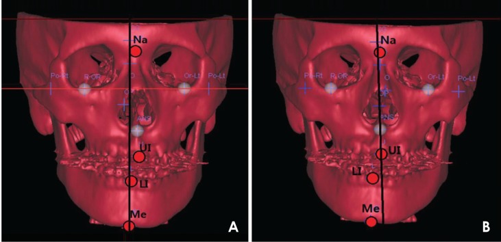
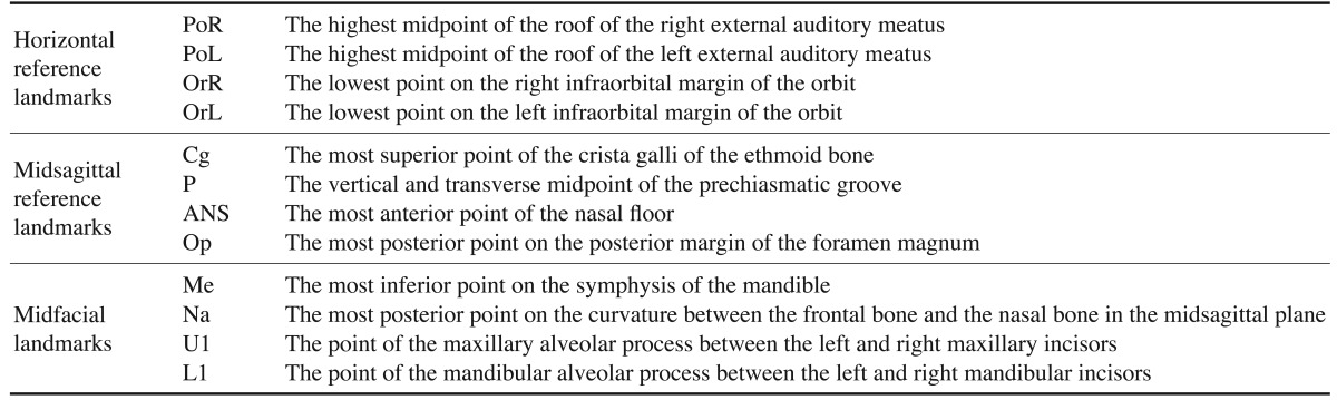
The surface shaded display was obtained with a threshold value of 126. Facial landmarks were identified and their location was confirmed on the axial, sagittal, and coronal planes. On each CT scan, horizontal reference landmarks (the right porion [PoR], left porion [PoL], right orbitale [OrR], and left orbitale [OrL]), midsagittal reference landmarks (crista galli [Cg], the prechiasmatic groove [P], anterior nasal spine [ANS], and opisthion [Op]), and midfacial landmarks (Me, nasion [Na], upper incisor [U1], and lower incisor [L1]) were identified (Table 1). Two distinct methods (Methods 1 and 2) of establishing the MRP were applied for each CT scan (Fig. 1). In Method 1, the PoR, PoL, and OrL landmarks were used to establish the horizontal reference plane (HRP), the Cg and P were used to establish the MRP, and the Op was used for establishing the coronal reference plane (CRP), with the three planes perpendicular to one another on Vworks. All of the data for the landmarks and planes were transferred to Vsurgery. In Method 2, the Op, Cg, and ANS landmarks were used to establish the MRP on Vsurgery for each CT scan, using the same values of Op and Cg as Method 1 (Table 2).
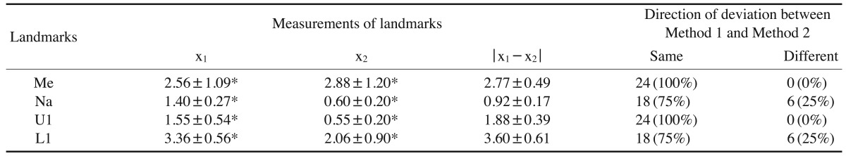
The x-coordinate, severity of asymmetry, and direction of deviation of the Me were compared between the two methods as follows. First, the x-coordinate of the Me was considered to be (+) when the landmark was located on the left side of the face and (-) when on the right. Then, Δx was defined as the difference between the x-coordinates calculated with Method 1 (x1) and Method 2 (x2). The severity of asymmetry was considered to be normal when the distance of the Me from the MRP (|x|) was less than 2 mm (0 mm≤|x|<2 mm), mild when less than 4 mm (2 mm≤|x|<4 mm), moderate when less than 8 mm (4 mm≤|x|<8 mm), and severe at values of 8 mm or higher (8 mm≤|x|).4 The direction (left or right) of the deviation of the Me was compared between the two methods.
The x-coordinates and directions of deviation for the Na, U1, and L1 were compared between the two methods in the same way as described above for the Me.
The one-sample t-test was performed using SPSS (IBM Corp., Armonk, New York, USA) to evaluate whether the Δx of the Me, Na, U1, and L1 landmarks varied to a statistically significant extent between the two methods.
Results
CT scans were obtained from 24 orthodontic patients with facial asymmetry, and 3D reconstructions of the CT scans were performed. Two methods of establishing the MRP were applied for each CT scan. The midfacial landmarks (the Me, Na, U1, and L1) were identified, and the x-coordinates and the direction of deviation of each landmark relative to the MRP were compared between the two methods (Fig. 1, Tables 3, 4, 5).
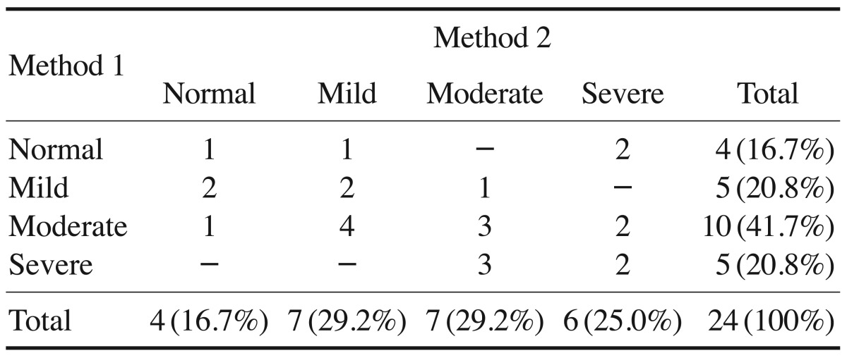
The direction of deviation for the Me was the same in both methods for all patients. The severity of asymmetry was the same in both methods in eight patients (33.3%). Differences were found in the severity of asymmetry in 16 patients (66.7%), with a difference of two or more stages in three patients (12.5%). The mean Δx was 2.77±0.49 mm, and a statistically significant difference was found between the methods (p<0.05). The value of Δx was between 2 mm and 4 mm in nine patients (37.5%), between 4 mm and 8 mm in three patients (12.5%), and 8 mm or more in two patients (8.3%) (Tables 3, 4, 5).
The direction of deviation for the Na was the same in both methods in 18 patients (75.0%), and different between the two methods in six patients (25.0%). The mean Δx was 0.92±0.17 mm, and a statistically significant difference was found between the methods (p<0.05). The value of Δx was between 2 mm and 4 mm in two patients (8.3%) (Tables 3 and 4).
The direction of deviation for the U1 was the same in both methods for all patients. The mean Δx was 1.88±0.39 mm, and a statistically significant difference between the methods was observed (p<0.05). The value of Δx was between 2 mm and 4 mm in five patients (20.3%) and between 4 mm and 8 mm in three patients (12.5%) (Tables 3 and 4).
The direction of deviation for the L1 was the same in both methods in 18 patients (75.0%), and different between the two methods in six patients (25.0%). The mean Δx was 3.60±0.61 mm, and a statistically significant difference was observed between the methods (p<0.05). The value of Δx was between 2 mm and 4 mm in three patients (12.5%), between 4 mm and 8 mm in eight patients (33.3%), and 8 mm or more in two patients (8.3%) (Tables 3 and 4).
Discussion
As a result of the recent increase in the general societal interest in esthetic appearance, the number of patients whose primary complaint is facial asymmetry is rising. The usage of CT has been extended to the 3D analysis of facial asymmetry,1920 which is performed by first establishing the appropriate reference planes, of which the MRP is the most fundamental. Several methods for establishing reference planes have been introduced for the 3D analysis of facial asymmetry.1789101421 The results of facial asymmetry analysis using CT can be influenced by the method chosen for establishing the reference planes, similarly to the influence of reference lines on facial asymmetry analysis when using 2D radiographs.1718 However, very few studies have evaluated the different methods used to determine the reference planes.171821
Therefore, this study compared the two most common methods (Method 1 and Method 2) of establishing the MRP and evaluated changes in the location of facial landmarks relative to the MRP according to the method of establishing the MRP. This evaluation was conducted by obtaining the x-coordinates of the midfacial landmarks Me, Na, U1, and L1, which can be used as reference points for analyzing facial asymmetry. The direction of deviation and the severity of asymmetry of each landmark was also evaluated according to each of the methods.
In the comparison of these two methods of identifying midfacial landmarks in the radiographs of 24 patients, the x-coordinates of the four midfacial landmarks showed statistically significant differences between the methods (p<0.05), which suggests that the method of establishing the MRP and the location of the Me, Na, U1, and L1 are significantly correlated (Table 3).
Although any facial structure can be asymmetric, structures in the lower third of the face have a higher prevalence of asymmetry than those in the upper and middle thirds. The deviation of the Me has been a point of particular interest.22 The Me has been identified as the most influential landmark in the perception of facial asymmetry, and has been used as the standard landmark for determining facial asymmetry on cephalometric radiography and 3D CT.2324
This study demonstrated that the x-coordinate of the Me significantly different depending on the method of establishing the MRP, which may have an impact on research into facial asymmetry.
The difference in the x-coordinates of the Me between the two methods of establishing the MRP was between 2 mm and 4 mm in nine patients (37.5%), between 4 mm and 8 mm in three patients (12.5%), and 8 mm or more in two patients (8.3%). A difference in the severity of asymmetry was observed in 16 patients (66.7%), with a difference greater than two stages in three patients (12.5%). Six patients (25.0%) were evaluated as being in the normal group of facial asymmetry by one of the methods, but in the asymmetric group by the other method. These results suggest that the diagnosis of asymmetry may differ according to the method used for establishing the MRP. It is uncertain which of these two methods is more reliable for determining the MRP (Tables 4 and 5).
The remaining three midfacial landmarks also showed significant differences in location according to the method used (p<0.05). The location of the Na showed a difference of 2-4 mm in two patients (8.3%). The location of the U1 showed a difference of 2-4 mm in five patients (20.3%) and 4-8 mm in three patients (12.5%). The location of the L1 showed a difference of 2-4 mm in three patients (12.5 %), 4-8 mm in eight patients (33.3%), and 8 mm or more in two patients (8.3%). The direction of deviation for the Na and L1 was different in six patients (25.0%). These results indicate that the method of establishing the MRP has a significant impact on the diagnosis of facial asymmetry (Tables 3 and 4).
In conclusion, this study showed that the x-coordinates of the midfacial landmarks may differ according to the method of establishing the MRP. The distance and direction of deviation, as well as the severity of asymmetry, may also be influenced by the method used. Depending on the method of establishing the MRP, the treatment plan could change and a different treatment outcome could result. Clinicians should be aware of this issue when assessing facial asymmetry and the location of landmarks.


 XML Download