

 PDF
PDF ePub
ePub Citation
 Print
Print


Introduction
Three-dimensional (3D) facial computed tomography (CT) is often performed on facial asymmetry patients who need orthognathic surgery because the technique provides accurate linear and angular measurements with no image superimposition and magnification, which are invariably present in two-dimensional (2D) radiographs. Usually, the first step in a 3DCT evaluation involves establishing three orthogonal reference planes: horizontal (HRP), midsagittal (MRP), and coronal (CRP). The eventual locations (x, y, z) of the landmarks are determined from these planes.1,2,3,4,5,6,7,8,9,10 The vertical positions of the landmarks are determined from the HRP, and the horizontal positions from the MRP. Because the frontal profile of the face matters the most in the evaluation of facial asymmetry, the processes of establishing the HRP and MRP are very important.
Various methods for establishing reference planes have been introduced depending on whether the HRP or the MRP is first established and depending on the landmarks used for the reference planes. The reference plane established second might be influenced by the reference plane established first. The crista galli (CR), porion (Po), and orbitale (Or) have been traditionally used as reference lines in 2D radiographic analyses,11,12 and they are also used as reference planes in 3D CT analyses. The prechiasmatic groove (P) or opisthion (Op) are additionally used for establishing reference planes in 3D CT.3,4,5,6,7,8,9,10 The landmark coordinates and facial analysis results might differ depending on the method of establishing the reference planes. Kim et al13 reported that different methods for establishing the MRP have yielded different deviations of the anterior nasal spine (ANS) and the genial tubercle from the MRP.
Thus, it can be presumed that the landmarks that can be used for the HRP and MRP in a 3D CT face analysis might deviate vertically or horizontally depending on the method of establishing the reference planes. This study aimed to investigate the deviation of landmarks that can be used for the HRP and MRP according to the methods of establishing the reference planes. To this end, each subject was analyzed using three different methods.
Materials and Methods
CT scans were selected from orthodontic patients who received orthodontic and orthognathic surgical treatments between 2002 and 2008 for improving facial asymmetry. Eighteen orthodontic patients were included in this study (10 males and 8 females; mean patient age: 33.6 years; patient age range: 18.1-39.1 years). The CT scan of each patient was analyzed with three different methods of establishing reference planes.
CT scans and 3D reconstruction of CT scans
CT scans were obtained using a spiral CT scanner (Light Speed QX/I, GE Medical Systems, Milwaukee, WI) with the following specifications: 512×512 matrix, 120kV, 200 mA, and gantry angle of 0°. The axial image thickness was 2.5 mm, table speed was 3 mm/s, and scanning time was 0.8 s. Digital imaging and communications in medicine (DICOM) images were created with a slice thickness of 1.0 mm. The acquired DICOM data were input into a personal computer. Using CT data, we reconstructed the 3D images with Vworks 4.0+Vsurgery (Cybermed, Seoul, Korea). A surface-rendered model was prepared, and the landmarks were defined on the surface-rendered model in Vworks 4.0 by an oral and maxillofacial radiologist.
A multiplanar reformatted image, volumetric model, and surface-rendered model of a CT scan, which were completely interfaced with each other using software, were constructed on Vworks 4.0. The landmarks were defined on the volumetric model with the guidance of the multiplanar reformatted image.
Three different methods for establishing reference planes
M1: The HRP (xy plane) was first established with the right Po (PoR), left Po (PoL), and left Or (OrL). Then, the MRP(yz plane) was formed perpendicular to the HRP and passing through the Cg and P. The CRP (xz plane), passing through the Op, was perpendicular to both the MRP and the HRP.3
M2: MRP (yz plane) was first established with the Cg, ANS, and Op.7,8,9 Then, the HRP (xy plane) was formed perpendicular to the MRP and passing through the right Or (OrR) and PoL. The CRP (xz plane), passing through the Op, was perpendicular to both the MRP and the HRP.
M3: The HRP (xy plane) was first established with the PoL, OrR, and OrL.10 Then, the MRP (yz plane) was formed perpendicular to the HRP and passing through the nasion (Na) and Op. The CRP (xz plane), passing through the Op, was perpendicular to both the MRP and the HRP.
Obtaining coordinates
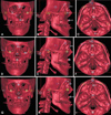
All image data and surface-rendered models were transferred to the Vsurgery program on which |z| was obtained for the horizontal landmarks (PoR, PoL, OrR, and OrL) for evaluating vertical deviation and |x| was obtained for the midsagittal landmarks (Cg, Na, P, Op, and ANS) for evaluating horizontal deviation. |x| is the distance from the MRP, and |z| is the distance from the HRP (Fig. 1). The three different methods (M1, M2, and M3) of establishing reference planes resulted in different landmark coordinates. Figure 2 shows an example of the results of using three different methods for determining the reference planes of one subject (Fig. 2). The landmarks and the reference planes for each method are summarized in Tables 1 and 2, respectively.
Results
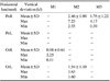
The vertical deviation (|z|) of the horizontal landmarks (PoR, PoL, OrR, and OrL) and the horizontal deviation (|x|) of the midsagittal landmarks (Cg, Na, P, Op, and ANS) were measured. The Po and Or, which were not considered when establishing the HRP, were not in the plane when using M1, M2, and M3. In M1, the PoR, PoL, and OrL were used for the HRP (|z|=0 mm), whereas the OrR deviated either upward or downward (|z|=0.98±0.61 mm). In M2, the PoR and OrL, which were not used for the HRP, deviated either upward or downward (|z|=2.46±1.90 mm, |z|=1.54±1.10 mm). In M3, the PoR, which was not used for the HRP, deviated either upward or downward (|z|=1.76±1.22 mm). In M1 and M2, either inferior orbital rim deviated from the HRP. Cg was used for establishing the MRP in M1 and M2, and its |x| was 0 mm. In M3, the |x| of the Cg was 0.81 ±0.58 mm, and the Cg deviated toward either side. In M1 and M2, the |x| of the Na, which was not used for the MRP, was 1.44±1.14 mm in M1 and 0.94±0.65 mm in M2. The |x| of the P was 0.96±1.01 mm in M2 and 0.94±0.74mm in M3. The |x| of the Op was 2.58±2.39 mm in M1. The |x| of the ANS was 1.92±1.74 mm in M1 and 0.97±0.67 mm in M3 (Tables 3 and 4).
Discussion
The key to a successful treatment of facial asymmetry is adequate analysis and diagnosis. Various methods of establishing reference planes in 3DCT have been introduced by many researchers.1,2,3,4,5,6,7,8,9,10 Some researchers have analyzed facial asymmetry using 3DCT by first establishing three orthogonal reference planes (HRP, MRP, and CRP), which allows for asymmetry measurement as well as planning for subsequent surgery. The rectangular coordinates (x, y, z) of the landmarks are determined from the orthogonal reference planes.2,3,4,5,7 The frontal profile is the most important in facial asymmetry analysis; therefore, among the three reference planes, the HRP and the MRP are of critical importance. Therefore, this study aimed to evaluate deviations of the landmarks used for establishing the HRP and the MRP.
The Po and Or are used to form the Frankfort line on cephalometric radiographs and to form the HRP on 3D CT. Among the four horizontal landmarks, that is, the PoR, PoL, OrR, and OrL, two or three are selected to make the HRP: the bilateral Po and unilateral Or, or unilateral Po and unilateral Or.3,4,5,6,7,8,9 The resulting faces showed a deviation of the other Or, or a deviation of the unilateral inferior orbital rim. The Or deviated by up to 3.63 mm in this study (Table 3, Fig. 2). Pelo et al14 reported that in their research using 10 subjects, no subject had a bilateral Po and bilateral Or on one HRP. It might not be possible to have the four horizontal landmarks located on the same plane. If the clinician prefers to have the bilateral Or parallel to the floor, the bilateral Or should be selected for the HRP, as in M3.10 It is suggested that the clinician should first determine whether the bilateral Or should be parallel to the floor.
Cg has been most commonly used for the mid-facial line in cephalometric radiographs11,12 and for the MRP in 3DCT, as in M1 and M2.3,6,7,8,9 Meanwhile, in M3, the Cg showed a lateral deviation (|x|=0.81±0.58 mm). The Na can be also used for the MRP.1,2,4,5,10 In this study, the Na deviated in M1 and M2 (|x|=1.44±1.14 mm in M1; |x|=0.94±0.65 mm in M2), where the Na was not used for the MRP. The deviation of the Na was up to 5.36 mm. These results can possibly be ascribed to the fact that the Cg is located inside the cranium and Na is located outside. When the Cg is used for the MRP, it is possible that the resulting face is deviated on either side (Table 4, Fig. 2).
The P or Op is used for the MRP.3,4,5,6,7,8,9,10 The P is a landmark on the anterior cranial fossa, and the Op is located in the most posterior position to the foramen magnum. The Op is one of the most reproducible landmarks in a 3DCT analysis.15,16,17 When the Op was used for the MRP, as in M2 and M3, the P deviated by up to 3.80 mm. Meanwhile, when the P was used for the MRP, as in M1, the Op deviated by up to 9.33 mm, which results in considerable facial deviation(Table 4, Fig. 2).
Anterior and posterior landmarks are needed for the MRP. Most anterior and posterior landmarks can be used to construct a better MRP that divides a head into two halves more precisely. Because the Na is located further anterior than the Cg and the Op is located further posterior than the P, the Na and Op can be used to construct a better MRP than that of the Cg and P.
The ANS is often used for forming the MRP.7,8,9 In this study, the ANS deviated laterally in M1 and M3 (|x|=1.92 ±1.74 mm in M1; |x|=0.97±0.67 mm in M3). The ANS, a landmark on the maxilla, can deviate if the maxilla has a deviation. Trpkova et al18 stated that the ANS is not suitable for establishing the mid-facial line on 2D cephalometric radiographs. Therefore, the ANS might not be suitable for generating the MRP in 3DCT either.
Facial asymmetry can be assessed differently depending on the mid-facial lines in 2D radiographs.18,19 Kim et al13 showed that a facial asymmetry analysis with 3DCT can be also influenced by the methods of establishing the reference planes, as is the case with reference lines in 2D radiographs. In addition, we showed that the landmarks used for HRP and MRP might be influenced by the methods of establishing reference planes and could deviate from the planes.
Facial asymmetry is not only about bone but also about soft tissue. Facial asymmetry in radiographs might appear different from that on real faces. In this study, we assessed only bony landmarks. Further study is needed with soft-tissue landmarks.
In conclusion, we evaluated the deviation of the landmarks used for establishing the HRP and the MRP in accordance with the methods of establishing the reference planes. There was a vertical or horizontal deviation of the landmarks depending on the methods used for establishing the reference planes. The clinician should be alert to establishing the reference planes in order to avoid an undesirable facial deviation. It is suggested that a face be evaluated by establishing reference planes using not only one method but two or more methods, which might be helpful for improving the accuracy of a facial analysis.


 XML Download