

 PDF
PDF ePub
ePub Citation
 Print
Print


Introduction
It is not unusual for healthy individuals to have minimal asymmetry of the face which does not cause any esthetic or functional problems.1-6 The range of acceptable minimal asymmetry should be understood prior to diagnosing problematic asymmetry that needs surgical intervention for esthetic and functional rehabilitation.
Researchers, using three-dimensional computed tomography (3D CT), have found that bilateral differences in some facial lines contribute to facial asymmetry.7-11 The distance or inclination of the lines connecting condyle landmarks and gonion landmarks (ramus length, ramal inclination from a frontal view, ramal inclination from a lateral view) and the distance of the line connecting the gonion and the menton (mandibular body length) might contribute to mandibular asymmetry.7,11 The facial lines can be more clearly defined by their length and vertical and horizontal angle in a spherical coordinate system.12
Spherical coordinate systems are used for various purposes such as astronomy and geology. For example, in geology, a spherical coordinate system describes a flying object over the earth with its distance from the center of the earth and its latitude and longitude. Symmetry of objects in 3D space can be also evaluated using a spherical coordinate system.13-18
For defining a facial line in 3D human structure, the spherical coordinate system can be modified to length, midsagittal and coronal inclinations, which are angles of the line relative to the midsagittal and coronal reference planes.12
This study aimed to obtain bilateral differences of facial lines from normal symmetric-looking faces without distinctive asymmetry in spherical coordinates, so this study's findings could provide a reference in the evaluation of facial asymmetry.
Materials and Methods
Study subjects
Twenty-two CBCT scans were selected for this study. The CBCT scans had been obtained from female patients (average age 24 years 8 months: age range from 18 years 3 months to 31 years 9 months) who had undergone surgical extraction of lower third molars and had needed CBCT scans for localization of the inferior alveolar nerve canal in relationship with the third molars.
The selection criteria of the study subjects were as follows; age of 18 years old or more, the mandible scanned including condyles and gonions by CBCT, class I occlusion, no plastic surgery history, and no distinctive facial asymmetry on clinical examination.
The average menton deviation of the subjects was 1.01±0.66 mm, which was measured as the distance of the menton from the midsagittal reference plane on CBCT. Since the study subjects had no distinctive facial asymmetry on clinical examination and the menton deviation was less than 2 mm,19,20 they were considered to have normal symmetric faces.
CBCT scans and 3D reconstruction of the CBCT scans
CBCT scans had been acquired using MercuRay (Hitachi, Tokyo, Japan) with a 512×512 matrix, 120 kV, and 15mA. The scanning time was 9 seconds. The field of view (FOV) had a 15 cm diameter in a globe shape. Five hundred twelve DICOM data were obtained with slice thickness of 0.29 mm. The acquired DICOM data were inputted into a personal computer. Using the CBCT data, 3D images were reconstructed by V-works 4.0+V-surgery software (Cybermed Co., Seoul, Korea). A multiplanar reformatted image, a volumetric model, and a surface-rendered model of a CBCT scan, which were completely interfaced with each other in the software, were constructed in V-works 4.0. The landmarks were defined on the volumetric model with the guidance of the multiplanar reformatted image.
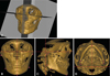
Table 1 shows the anatomical landmarks, reference planes, and facial lines used for this study. Three orthogonal reference planes, the horizontal (xy plane), midsagittal (yz plane), and coronal (xz plane) reference planes were established. The horizontal reference plane was first established using right Po, left Po, and left Or.7,21 The midsagittal reference plane was then formed perpendicular to the horizontal reference plane and passing through Na and Dent.22 The coronal reference plane was perpendicular to both the midsagittal and the horizontal reference planes passing through Dent.22 The condylar landmarks were identified as the most superior (Cdsup), lateral (Cdlat), and posterior (Cdpost) points of the condylar head. The gonion landmarks were identified as the most inferior (Goinf), lateral (Golat), and posterior (Gopost) points of the gonion area. The menton (Me) was defined as the most inferior point on the mandibular symphysis (Table 1, Fig. 1).
All image data and surface-rendered models were transferred to the V-surgery program (Cybermed Co., Seoul, Korea), where the rectangular coordinates (|x|, y, z) of the landmarks were acquired. |x| was the distance from the midsagittal reference plane, y was the distance from the coronal reference plane, and z was the distance from the horizontal reference plane; |x| was set to absolute values.
The facial lines, ramal height (RH: line Cdsup-Goinf), ramal lateral (RL: line Cdlat-Golat), ramal posterior (RP: line Cdpost-Gopost), and mandibular body (MB: line Gopost-Me) were established relative to the landmarks.7,11 The side of the face on which Me was placed was identified as the deviated side, while the contralateral side of the face was considered to be the opposite side. The rectangular coordinates of the starting landmarks of the facial lines, Goinf, Golat, and Gopost, were obtained. The bilateral differences of the starting landmarks of the facial lines (dx, dy, dz) were obtained and their means were calculated, where (dx, dy, dz) was (xdeviated-xopposite, ydeviated-yopposite, zdeviated-zopposite). The menton was excluded because one point of the menton was used for the bilateral lines for MB in each individual (Table 1).
Spherical coordinates of the facial lines
The alternate spherical coordinates of the facial lines, RH, RL, RP, and MB, were obtained from the rectangular coordinates of the landmarks. As for RL, (xcd-xgo, ycd-ygo, zcd-zgo), (xcd, ycd, zcd) was for Cdlat, and (xgo, ygo, zgo) was for Golat. When x=xcd-xgo, y=ycd-ygo, and z=zcd-zgo, the alternate spherical coordinates (v, θ, ϕ) were calculated as below:

for θ, ϕ in radian measure (θrad=θ°×π/180), where v was the distance of the lines; θ, midsagittal inclination, was the angle inclination from the midsagittal reference plane; ϕ, coronal inclination, was the angle inclination from the coronal reference plane.12
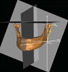
The spherical coordinates of the facial lines were acquired on the deviated and opposite sides. The means of the spherical coordinates of the deviated and opposite sides were compared by a paired t-test. Null hypotheses of no difference were rejected if the p-values were less than 0.05. The mean and standard of the bilateral differences (dv, dθ, dϕ) between the deviated and opposite sides were obtained, where (dv, dθ, dϕ) was (vdeviated-vopposite, θdeviated-θopposite, ϕdeviated-ϕopposite) (Fig. 2). Statistical analyses were performed using SPSS version 15.0 software (SPSS, Chicago, IL, USA).
Results
The bilateral differences of the starting landmarks of the facial lines (dx, dy, dz) between the deviated side and opposite side were obtained. The bilateral differences of the starting landmarks were (-0.08±3.01 mm, -1.08±3.8 mm, 0.29±3.36 mm) for Golat, (0.56±3.39 mm, 0.31± 3.36 mm, 1.80±3.22 mm) for Gopost, and (0.48±3.23 mm, 0.18±3.18 mm, 0.90±3.04 mm) for Goinf (Table 2).
There was no statistically significant difference between the spherical coordinates of the deviated and opposite sides. The bilateral differences of the facial lines in the spherical coordinate system (dv, dθ, dϕ) were (-0.62±3.69 mm, -0.86±2.18°, 1.28±3.14°) for RH, (-2.10±3.24 mm, -0.88±2.07°, -0.42±3.52°) for RL, (-1.29±2.64 mm, -1.45±3.58°, -0.39±4.53°) for RP, and (-0.09±2.46 mm, -0.93±2.72°, -0.52±2.26°) for MB (Table 3).
Discussion
Accurate diagnosis is essential for ensuring a good treatment plan and postoperative evaluation for facial asymmetry. Three-dimensional CT has an advantage over two-dimensional (2D) cephalometric radiographs in depicting 3D human anatomic structure. Three-dimensional CT depicts the human face without superimposition, magnification, or distortion of anatomic structures, all of which are inherent on 2D cephalometric radiographs. This study aimed to measure the bilateral differences of the facial lines in spherical coordinates from the faces with a normal range of asymmetry utilizing 3D CBCT.
In this study, CBCT was used for 3D CT analysis of facial asymmetry in normal individuals. Studies have reported that the linear accuracy of CBCT was similar to that of CT.23,24 The mean difference between the actual measurement on the skull and measurement on CT was 0.83% in the study by Cavalcanti and Vannier23 and -1.13 ±1.47% in the study of Periago et al.24 The accuracy of the linear measurement on CBCT was acceptable for 3D facial analysis.
This study showed that there were minimal differences on the starting landmarks of the facial lines in all of the study subjects (Table 2). No perfect symmetry of facial lines in spherical coordinates was seen in any study subject. All of the subjects had somewhat asymmetrical facial lines, though there was no statically significant difference between the deviated and opposite sides. Considering only the mean value, the facial lines of the deviated side were shorter and more erect toward the midsagittal reference plane than those of the opposite side, the RH and RL of the opposite side were more erect toward the coronal reference plane than that of the deviated side, and the RP and MB of the deviated side were more erect toward the coronal reference plane than those of the opposite side (Table 3).
Several researchers have developed standard values for the normal range of asymmetry by obtaining bilateral differences of landmarks in rectangular coordinates for hard or soft tissue analysis on 3D CT.21,22,25,26 However, there has been no study on the normal range of asymmetry of facial lines. The spherical coordinate systems were applied for this study to obtain the normal range of asymmetry of the facial lines, which might be critical contributing factors to facial asymmetry.7,11
In conclusion, the normal range of facial asymmetry in the spherical coordinate system in this study should be useful as a reference for planning treatment of facial asymmetry and for evaluation of facial asymmetry of the postoperative state. This study was limited by the inclusion of females only, whose faces are small enough for the condyles and chin to be projected in a 15 cm diameter FOV of CBCT, the maximum FOV that the machine allowed. The sample size in this study was only 22 female subjects. Further study with a larger sample size of male and female subjects using CBCT with a wider FOV is needed.


 XML Download