

 PDF
PDF ePub
ePub Citation
 Print
Print


Introduction
Panoramic radiography visualizes the relationship of maxillofacial structures within the focal trough. It also provides information on the location of the inferior alveolar canal and the maxillary sinuses in relation to the alveolar crest. It can reveal approximate bone height, vital structures, and any possible pathological conditions in the area.1 Despite the fact that newer techniques such as computed tomography (CT) and magnetic resonance imaging (MRI) can provide more accurate information, panoramic radiography is more commonly performed, as it produces less radiation exposure than CT and is less expensive than CT and MRI.2 One of the main parameters that may cause magnification and distortion is the patient's head position within the panoramic device. A previous study showed that unacceptable radiographs were mostly due to poor head positioning techniques rather than technical errors.3 Image distortion and magnification compromise the dimensional accuracy of panoramic radiography. If the degree of magnification in the horizontal and vertical dimensions was the same in the central plane of the focal trough, all of the structures, including the upper and lower teeth, would be in focus on the final radiograph.4 In panoramic radiography, the focal trough is narrow in the anterior and wider in the posterior areas. Therefore, changing the head position would have greater effects on the degree of magnification in the anterior region.5,6
Angular measurements are often used to determine the axial inclination of the impacted teeth and accurate tooth position in order to ensure the parallelism of the roots in orthodontic treatments, determine the crown angulation, and evaluate edentulous areas for implant treatment planning.7 Some studies have evaluated the accuracy of these measurements; however, they have yielded controversial results.8-10 Image magnification and distortion, the great disadvantages of panoramic images, usually occur during radiography, limiting the dimensional accuracy.11 Moreover, the degree of magnification is not the same throughout the image. Distortion results from different extents of magnification in the horizontal and vertical dimensions in various parts of an image.11
As panoramic radiography is commonly used for diagnosis and treatment planning, the present study was conducted to determine the accuracy of the linear and angular measurements and crown-to-root ratios on panoramic radiographs at 5 different positions.
Materials and Methods
In this in vitro experimental study, a mandibular cast with class I occlusion was selected from the archives of the Department of Orthodontics, Shahid Beheshti University of Medical Sciences. A wax model with an appropriate thickness was made from the mandibular cast in the form of a mandibular arch. Dental stone was poured around it, wax burnout was carried out, and the acrylic model was fabricated. Two duplicates were fabricated from the acrylic model (a total of 3 acrylic models). The first acrylic model was used for the pilot study, and the other two were employed for the main study. The acrylic models had a 15-mm width and 5-mm thickness.
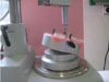
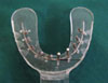
The acrylic model was placed over the cast and 10 spots indicative of the location of teeth were marked on the acrylic model (4 spots for molar teeth, 2 spots for premolars, 2 spots for canines, and 2 spots for incisors). The marked spots were perforated (Fig. 1) and 10 screws were inserted into the holes in such a way that a few screw threads were above and a few were below the acrylic model (Fig. 2). To ensure the correct positioning of the screws within the focal trough of the panoramic image, a pilot study was conducted using the first fabricated acrylic model. In the pilot study, several consecutive panoramic radiographs were taken from the model and by changing the location of screws, their accurate location and focal trough were specified.
In the remaining two acrylic models, 10 stainless steel round cross-section pins (2.4 cm in length and 2.5 mm in diameter) were placed in locations similar to the screws in the pilot study. In the first acrylic model, the pins were inserted into the model perpendicular to the acrylic surface. In the second acrylic model, five pins were placed in the right side of the model at a 75° mesiodistal angle relative to the surface. These pins were coded R1 to R5 starting from the end of the right mandibular quadrant towards the midline. The remaining five pins were placed in the left side with a 75° buccolingual angulation. These pins were coded L6 to L10 starting from the midline towards the end of the left mandibular quadrant. A threaded wire (1 mm in diameter) was bonded to the acrylic model adjacent to the pins conforming to the acrylic model arch simulating the occlusal plane on the radiographic image. The pin length located above and below the wire represented the "crown" and the "root" portion, respectively.
Angulations of the pins and preparations of the holes on the acrylic model for placement of the pins were performed with a Digital Level Box (Cem Red, Beijing, China) and Paraskop PM milling machine (BEGO, Bremen, Germany) in the Prosthodontics Laboratory of Shahid Beheshti Dental University. The length of the crown and root portion of the pins and their total length on the acrylic model were measured using calipers (Dentaurum, Ispringen, Germany). Both acrylic models were separately placed on the bite piece (where the patient's anterior teeth are placed) of the M 2002 CC Proline panoramic imaging system (Planmeca, Helsinki, Finland). The Digora PCT model photostimulable phosphor (PSP) digital image plate (Sordex, Helsinki, Finland) was inserted in the place of the film screen in the panoramic imaging system. Radiographic images were obtained at different positions with appropriate exposure settings (18 seconds, 4 mA, 60 kVp) (Fig. 3A) as outlined below.
P1: An 8° downward tilt of the occlusal plane in the anterior segment with no lateral tilting to imitate a standard occlusal plane12
P2: A 16° downward tilt of the occlusal plane in the anterior segment with no lateral tilting (8° lower than the previous position)
P3: An 8° upward tilt of the occlusal plane in the anterior segment compared to the standard position with no lateral tilting
P4: A 10° downward tilt of the right side of the model (lateral left cant of the occlusal plane)
P5: A 10° downward tilt of the left side of the model (lateral right cant of the occlusal plane)
In order to determine the angulation of the acrylic model in the above-mentioned positions in the panoramic imaging system, a Digital Level Box was used.
A second radiograph was also taken from the acrylic model in the five positions after removing and repositioning the model in the same place to confirm reliability of the technique. Based on the Cronbach's alpha test, the reliability value ranged from 0.6816 to 0.9668.
The image plate was placed inside the Digora PCT scanner (Sordex, Helsinki, Finland). The image was scanned, and since the magnification factor of the panoramic unit was 1.2, 1 was divided by 1.2 (the exact zoom was determined to be 0.83) and entered into the print menu of the image processing software to provide actual-sized images. The images were printed using a DRY PIX 4000 printer (Fuji Film, Tokyo, Japan) (Fig. 3B). The two radiographs were also superimposed to evaluate any significant distortion. After ensuring that no significant differences existed between the first and second radiographs, one film was selected randomly. Eventually, 10 panoramic radiographs were selected (5 from the first and 5 from the second acrylic model). Angular and linear parameters were measured on the radiographs. The measurements were performed by an oral and maxillofacial radiologist who was not aware of the position of the model in each radiograph, and thus, the risk of bias was eliminated. Linear measurements were carried out with a caliper while a cephalometric protractor measured the angular measurements (Ortho Organizers, San Marcos, TX, USA). The measurements of each radiograph were repeated 3 times in 2-day intervals, and the mean value was used for the final calculations. By repeating the measurements three times, the intra-observer reproducibility was increased. Finally, the length of the pins above (crown) and below (root) the occlusal plane, total pin length, crown-to-root ratio, and angulations of the pins relative to the occlusal plane were measured.
Data were entered into SPSS 15.0 (SPSS Inc., Chicago, IL, USA) software. The differences between the measured and actual values were calculated. Central distribution indices (mean, standard deviation, minimum, and maximum) were also calculated and reported. The changes in the angular and linear measurements on panoramic radiographs taken at different positions were evaluated using repeated measures analysis of variance (ANOVA). Also, pair-wise comparison of positions was calculated using the least significant difference (LSD) test for multiple comparisons. For determining the similarity of values at different positions, an intraclass correlation coefficient was used. P<0.05 was considered statistically significant.
Results
The measurement of the crown, root, and total length values of the angulated pins on the panoramic radiographs revealed that the buccolingual (L6-L10) and mesiodistal (R1-R5) angulation of pins, and the length of the roots, crowns, and total length of the pins at the P2, P3, and P4 positions decreased. However, no reduction in the root, crown, or total length was detected in P1 and P5.
The comparison of the values obtained for the straight pins with their true values demonstrated that the length of the pins and all of the crowns increased; however, the length of all of the roots decreased from positions P1 to P5. This difference was the greatest at P2 and the lowest at the P3 position. The total length of the pins decreased in all five positions, showing that the reduction in root length was greater than the increase in crown length. The total length of the pins increased at P4 (in the L9 and L10 pins) and P5 (in the L9 and L10 pins) positions.
During the angular measurements, the standard position (P1) was considered to be the baseline as the angles could not be measured on the acrylic model, and therefore all of the other positions were compared with P1.
The comparison of different parameters in the angulated pins with their true values revealed that the mean difference in crown length between the amount measured on the panoramic radiograph and baseline value was within the range of 0.15mm(at P1) to 0.29mm(at P4).This range was -0.32mm(P2) to -0.99mm(P5) for the root length. The mean difference in angulations of the pins relative to the occlusal plane at different positions compared to P1 was within the range of 0.6° (P3 and P5) to -0.95° (P2). The mean difference in the crown-to-root ratio on the panoramic image compared to the baseline was in the range of -0.007 (P2) to -0.49 (P3). The mean difference in the total pin length was -0.49 mm (P2) to -0.84mm(P5).
When comparing the straight pins with their actual values, the mean difference in the crown length between the amount measured on the panoramic radiograph and baseline value was within the range of 0.35mm(at P3) to 0.61mm(at P2). This range was -1.72mm(P3) to -0.42 (P2) mm for the root length. The mean difference in the angulations of the pins relative to the occlusal plane at the different positions compared to P1 was within the range of 0.45° (P5) to -1.15° (P2). The mean difference in the crown-to-root ratio on the panoramic image compared to the baseline ranged between 0.04 (P2) to 0.12 (P3). The mean difference in the total pin length was -0.07 mm (P2) to -1.11mm(P3).
The results of repeated measures ANOVA for evaluation of linear changes in the crown length of the angulated and straight pins in various positions demonstrated that this difference was statistically significant (P<0.001 and P<0.005, respectively). In other words, when the position of the pins was varied (which is indicative of the patient's head position changing), significant alterations occurred in the crown length on the image in both groups. The LSD multiple comparisons test found significant differences during paired comparison of the 5 positions (except for P1 and P4, P3 and P4, and P4 and P5 in the angulated pins and P1 and P2, P1 and P4, P2 and P4, P3 and P4, P3 and P5, P1 and P5, and P4 and P5 in the straight pins). Thus, the positions mentioned did not differ significantly from each other in terms of crown length changes. It seems that the P2 position was not similar to any other position.
According to repeated measures ANOVA, the differences in the angular measurement of the angulated and straight pins relative to the occlusal plane were not statistically significant in different positions (P>0.05). Thus, when the position of the occlusal plane was changed (altered head position), no significant changes would occur in the angulation of straight or angulated pins relative to the occlusal plane at different positions.
Discussion
Our results showed that the changes in the position of the occlusal plane (indicative of the patient's head position) did not cause significant alterations in the angulations of straight or angulated pins relative to the occlusal plane. Thus, upward or downward tilt of the occlusal plane (8° with no tilt) or 10° right or left side tilting did not result in considerable changes in the angular measurement of pins relative to the occlusal plane.
Tronje et al concluded that the changes in the buccolingual inclination of the teeth within certain limits would not cause linear errors on panoramic radiographs.13 This finding agreed with our study. Their study showed that errors did not exceed 10% of the actual length. The true length of the object used was shorter than 10 mm; however, the length of pins used in our study was 2.4 cm. Therefore, their finding might be attributed to the compensation in the relative magnification factor of the panoramic machine. They stated that the placement of an inclined object at both sides of the focal trough resulted in varying degrees of magnification. However, this was true only for measurement of vertical distances and objects positioned at the center of the focal trough. This finding was contradicted by other studies that claimed that if the buccolingual inclination of the teeth increased within the focal trough, or different panoramic units were used, greater errors would occur.14,15
Batenburg et al demonstrated that counter-clockwise rotation of the mandible resulted in neck extension and reduced intermaxillary space, and therefore, longitudinal projection of structures located at the tip of the mandible increased; on the other hand, clockwise rotation of the mandible caused neck flexion and increased the intermaxillary space and so decreased the magnification.5 Their study revealed that panoramic radiography was inadequate for assessment and diagnostic purposes in the patients with edentulous mandible unless more attention was paid to the patient's head positioning in the panoramic unit. In accordance with their results, we also found significant differences in the linear measurements performed on the panoramic radiographs in comparison with their actual lengths. Hoseini Zarch et al also found that 83% of linear measurements were underestimated.16 They concluded that linear measurements on panoramic radiographs were more reliable for the posterior regions in comparison to the anterior segments. However, overall, we might conclude that panoramic radiography would not be reliable for linear measurements.
Pfeiffer et al evaluated the effect of changes in head position enlargement of structures on digital panoramic radiography, and they concluded that head positioning, angulations, anatomical site, and distance orientation could affect the horizontal measurements.17
Another study evaluated the size, shape, and position of the focal trough in panoramic radiography by assessing the formation of a radiographic image in different anatomic positions and reported varying magnifications in both the horizontal and vertical axes.18
The linear measurements in our study were shown to be accurate, and this was in contrast with the results of Stramotas et al in 2002.12 They reported that the accurate measurement of structures on panoramic radiographs was feasible when sufficient care was taken with head positioning. According to their study, when the occlusal plane was tilted up anteriorly by 8°, the angular changes at different positions were all less than 5° and thus clinically insignificant. This finding was similar to our study results. Even though the angular measurements in their study were compared with the initial measurements on the model, we could not perform angular measurements on the model, and thus P1 position was considered to be the standard position. On the other hand, Hardy et al showed that a change in the vertical head position resulted in significant changes in axial tooth inclination, which might be justified considering the different panoramic units used in their study and ours.19
Furthermore, Lucchesi et al revealed that panoramic radiographs were inadequate for measuring various structures and could not accurately record the mesiodistal root angulations and root parallelism in posterior areas.15 This could originate from the inaccurate position of the patient's head and errors related to patient movement during exposure.3 A study reported that unreliable panoramic radiographs mostly resulted from backward rotation of the head. Lateral rotations around the sagittal axis (Y-axis) up to 10 degrees were also shown to have a negligible effect on the accuracy of images.20 Upward angulation of the occlusal plane could cause significant changes in tooth angulations.
Measurement errors more commonly occur in the imaging of bony structures because these images depend on bone density at the evaluation site. For instance, when assessing the bone loss or bone deposition at implant locations, the value of magnification relative to the implant position should be calculated, and changes in the clarity of skeletal tissues should also be considered since they can affect the margin of bony structures and affect the study results. The accuracy of linear and angular measurements on panoramic radiographs could be affected by the size, form, and position of the jaws in the X-ray machine.19 Thus, further studies would be required in this respect.
In our study, the occlusal plane was used as the reference line for the linear measurements, as it was directly associated with the markers (like the stainless steel pins) and it moved constantly with the pins when the model was slanted in any particular direction. Thus, the angulations would not necessarily deviate dramatically with a slight inclination of 10° or less. However, according to Stramotas et al, any deviation over this value might cause high rates of distortion.12
Measurement of the crown-to-root ratio in prosthodontics treatments is as important as linear and angular measurements. However, crown-to-root ratio measurement has been evaluated in few studies, and Stramotas et al found no significant differences in this respect at various positions.12
In conclusion, this study demonstrated that the change of the position of the occlusal plane or patient's head resulted in significant alterations in the length of both straight and angulated pins compared with the actual values (P<0.05). The linear measurements on panoramic images differed significantly from the actual values, and this difference was more significant for the crown segment of the pins. The tilting of the occlusal plane within 8 degrees showed significantly smaller errors compared with that of 10 or more degrees (P<0.05), and it seemed that the tilting of the occlusal plane by 10 or more degrees should be avoided. In general, relatively accurate angular measurements could be obtained using panoramic radiographs with occlusal plane variations of less than 10 degrees, and the radiographic unit was able to compensate for the effect of minor changes in the position of pins.

 XML Download