

 PDF
PDF ePub
ePub Citation
 Print
Print


Introduction
Ever since the first dental implants have been introduced by Branemark et al1 in 1969, more than four decades ago, dental practitioners and researchers have been searching for various methods for improving the accuracy of the surgical placement of implants. Advances in dental imaging technology utilizing computed tomography (CT) has been proven especially useful when determining the installation sites of dental implants.2-8 However, even though the CT images may provide accurate anatomical information of the jaws, the final decision is performed by the surgeon placing the implants.2-8 Therefore, the operator's experience and skills become a critical factor in successful implant therapy, and for those surgeons lacking sufficient expertise for specific clinical situations, positioning and installing implant fixtures often become highly arduous tasks.2-8 To cope with the problem, more attention is now being paid to image-guided implantology, which is designed to aid surgeons when performing implant treatments.9-12
Currently, one of the most popular systems is based on the CAD/CAM concept, which produces a 3-dimensional (3D) rapid processing (RP) jaw model with 3D CT imaging, and fabricates surgical stents for this RP model.13 Though this stent, leaving a hole in the position for fixture installation, may be advantageous in placing implants precisely, it has its setbacks due to the complex procedures required, errors during RP model fabrication, and high costs.14,15 A modified system aimed to reduce costs and effort was proposed, which attached a framework to the patient's face prior to taking CT images and setting the stent holes on the basis of this framework.16,17 However, it was inconvenient to use and there were possible errors during the fixation of the framework on the patient's face. Pongracz and his coworkers developed a software program, allowing intuitive treatment plans using 3D CT images.18 With the software, both virtual planning and virtual surgery were made possible. However, transferring virtual information to actual operations had many shortcomings. Koulechov and Lueth proposed tracing the position of an operative drill for automated implant surgery.19 This method showed high accuracy in tracing drill position with very limited errors, but its use in the oral cavity was restricted due to the large tracking devices attached to the drills. Another method used radiopaque markers inserted into the dentures of the patients, and CT images were taken to place guide holes based on the marker locations of the dentures. However, this method was only applicable to patients with complete dentures, and produced potential errors from ill-fitting dentures.20
So far, CT-guided template production techniques have been either inclined toward precision, or focused on feasibility regarding costs and easy application. It is necessary to develop a method with both high accuracy and feasibility for clinical settings.
The purpose of the present study was to evaluate the accuracy of a newly developed CT-guided surgical stent with a simple design.
Materials and Methods
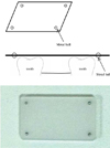
A hog dry mandible, with a molar extracted on each side, was used throughout the experiment for surgical stent fabrication and CT image taking. An impression of the mandible including the alveolar bone and teeth was taken, using silicone rubber impression material (Fegura-Sil hydro spezial II, Feguramed GmbH, Buchen, Germany) and an impression tray made with baseplate wax. From this impression, a stone cast was prepared. On the stone cast, an occlusal stent that registered the occlusal surface of the hog's teeth was fabricated using a resin plate according to common clinical protocol. With the stent applied, the edentulous area of the mandible was filled with resin up to the level of the occlusal surface of the adjacent teeth. On the edentulous area of the occlusal stent, a specially designed plastic plate (20×35×2 mm) was attached to serve as a reference plane on CT images. For radiographic recognition, a metal ball (2 mm in diameter) was inserted in each of the 4 corners of the plate 2 mm apart from the edge of the plate (Fig. 1).
CT images of the hog mandible, with the surgical stents applied on both sides, were taken using a multi-detector spiral CT machine (Somatom Sensation 10, Siemens, Erlangen, Germany). The conditions of the CT images were as follows: Slice thickness of 0.75 mm, 120 kVp, 100 mAs, gantry 0°, 0.254 pixel spacing, and reconstruction interval of 0.6 mm. The CT images were saved in DICOM format, and the data were transferred to the V-Implant (Cybermed, Seoul, Korea) software.
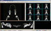
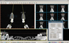
Reformatted and recombinant images including panoramic, cross-sectional, and 3D images as well as axial images were acquired from the CT data. The positions and directions of the implants were planned using the additional functions of the V-Implant software. The software expressed numerically the spatial position of the virtual implant axis with the coordinates of the insertion point and the angle relative to the reference plane. The reference plane on the CT images was determined by connecting the center of the radiopaque metal balls in the plastic plate. The procedure determining the center of the metal balls and the resultant reference plane was automatically performed by the software. The data of the spatial positions for the virtually installed implants were recorded in the software (Fig. 2).
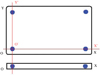
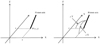
The detailed procedure calculating the spatial position of the central axis of the virtually installed implant was as follows. The line connecting the 2 metal balls aligned to the long axis on the plastic plate was set as the X-axis, and the other line aligned to the short axis was set as the Y-axis. The point of intersection was set as the datum point O, thereby constituting the XOY-plane (Fig. 3). The X and Y coordinates of an insertion point P(x, y) was determined by the crossing point between the axis of the virtual implant and the XOY-plane, and the angle between the axis of the virtual implant and the XOY-plane was determined as Xθ and Yθ according to the X-axis and Y-axis, respectively (Figs. 4 and 5).
The virtual installation of implants was performed with five different inclinations from the occlusal plane, i.e., perpendicular, buccal, lingual, mesial, and distal. Each inclination but the perpendicular one had two different angulations, 10° and 20°. Thus, the planned implants were divided into 9 groups according to their axis inclination and angulation. For each group, 10 fixtures were placed, 5 on each side (5 on the right side of the mandible, 5 on the left side of the mandible). Therefore, a total of 90 fixtures were virtually inserted.
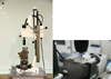
The data of the virtually installed fixtures as mentioned above were transferred to a specially designed 5-axis drilling machine (Fig. 6A) and the implant guiding holes were drilled into each surgical stent. The drilling procedure was as follows: The plastic plate, used as a reference plane, of the surgical stent was fixed parallel to the table of the drilling machine. By moving and rotating the table of the machine, which can control the position and angulation of the table by rotating each of its 5 axes, the spatial position of each virtual implant axis was reproduced on the table of the machine. Finally, guide holes were drilled into each of the surgical stents (Fig. 6B). A total of 90 surgical stents, each with a guide hole (9 groups according to the inclination and angulation of the virtual implant axis, and 10 stents for each group), were drilled.
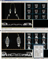
After applying the stents to the hog mandible, CT images were taken under the same conditions as taken previously. The spatial position of the drilled holes was acquired on the software. The procedure for determining the spatial position of the drilled holes was as follows: The drilled guide hole was shown as a black cylindrical area on the CT images, and placing a virtual implant into the guide hole was performed on the software (Fig. 7A). After confirming the virtually positioned implant to be placed exactly into the image of a guide hole, the position and the angulation of the central axis of the guide hole were calculated automatically by the software (Fig. 7B).
The spatial positions of the drilled holes were then compared with those of the virtually installed implant in the planning phase. The discrepancy between them was calculated and recorded as the amount of error for this system.
Results
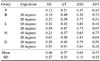
Table 1 shows the discrepancy of the X, Y coordinates and the angulation for each group. The insertion point of the implant axis on the plate was described as the X and Y coordinates.
The discrepancy of the insertion point P (x, y) ranged from 0.12 mm to 0.93 mm on the X-axis and from 0.21 mm to 0.91 mm on the Y-axis. The discrepancy of insertion angulations to the XOY-plane (Xθ, Yθ) ranged from 0.35 to 0.89 on the X-axis and from 0.45 to 0.77 on the Y-axis. The mean values of ΔX, ΔY, ΔXθ, and ΔYθ were 0.46mm, 0.57 mm, 0.64°, and 0.57°, respectively.
For the two different angulations in each group, 20 degree angulation showed a greater error in the deviation of the insertion point P (x, y) than 10 degree angulation, but not in the discrepancy of the angle.
Discussion
The present system used a plastic plate with metal balls to determine the reference plane, and the procedure is relatively simple and performed commonly in dental clinics. Even though the procedure was simple and cost-effective, the resultant stent still provided an accurate template.
Previous studies have shown that, in general, the accuracy of implant placement using surgical stents will be higher than that of implant placement without stents. However, its accuracy will depend mostly on the operator's technique.21,22 Recently, several studies using objective numerical values have been conducted to evaluate the accuracy of implant guiding systems, specifically, the quantified accuracy of automatic position-trace systems. Widmann et al evaluated the accuracy of automatic position tracing system based on deviation from the reference point, and the average error was 0.42±0.26 mm (1 mm maximum).23 Brief et al used a coordinate measuring device called the 'Faro arm', and they reported an error of 0.60 mm and 2.12°.24 Using mutual information registration, which evaluated the deviation of the fixture position by superimposing CT images before and after the surgery, Wanschitz et al reported that the accuracy was 0.96±0.72 mm (range 0.0-3.5 mm).25 Van Steenberghe et al inserted zygoma implants using a 3D CT system and reported that angulation errors of most implants were not greater than 3° and that the largest error was 2.7 mm.26 The deviation of the entry point and angulation for the system proposed in the present study were 0.47±0.27 mm, 0.57±0.23 mm, 0.64±0.16°, and 0.57±0.15°, respectively, and this shows that this system is highly accurate. The range of errors acquired from the present study were similar to, or more accurate than, those obtained from previous studies.
We attempted to exclude the errors that may have been caused by surgeons and only focused on evaluating the in vitro accuracy of the guide holes of the stents. However, any possible accidental errors that may have occurred in the course of the clinical surgery could have affected the results profoundly. Therefore, for clinical applications, additional studies regarding surgeon factors should be performed.
There are some limitations in the present system. First, an error could originate from the partial volume averaging effect of the CT image. This kind of error occurs when the shape of the spherical metal ball, inserted in the plastic plate, is ovoid rather than round on the CT images. Because the virtual reference plane is set by connecting the centers of the metal balls on the CT images, discrepancy between a virtual reference plane and the real one might be caused, when the center of the metal ball on the CT images was different from the center of the real ones. This phenomenon might happen everywhere in the guide stent system, to all the structures, since resolution in the longitudinal direction is lower than that in the axial direction, which means that the voxel of the CT is not isotropic. This is inevitable, due to mechanical limitations of the CT itself. However, in the present study the minimum CT slice thickness of 0.75mm was used to minimize this error. If dental cone beam CT with isotropic voxel and higher resolution can be used, this error will be reduced further.
Second, the error may also originate from the drilling procedure. Before the guide hole is made in the stent using the specially designed 5-axis drilling machine, the reference plane including the 4 metal balls and the datum point O, which was the cross point of the X-axis and the Y-axis, is determined. For drilling, the drill tip should be placed on the datum point of the plastic plate (the datum point settlement), and afterwards the table of the machine should be moved according to the calculated values from the software. In the present study, however, it was not easy to precisely place the drill tip at the datum point because the drill tip was not sharp enough. Especially when the plastic plate was inclined to reflect the angulation of the central axis of the virtual implant fixture, it was not easy to accurately set the datum point with the drill tip spatially. We think that is why 20 degree angulation showed a greater errors in the deviation of the entry point than did 10 degree angulation.
During the drilling procedure in the present system, this kind of error seems to have originated from datum point settlement. Improvements in settlement of the datum point and the design of the plastic plate are needed.
Third, after the datum point settlement, the plastic plate fixed to the machine table should be moved using a scale attached to each axis to avoid any possible errors. The minimum distance of the table movement was 0.02 mm, and the minimum angulation of the table inclination is 1/30; therefore, the values below the limitation cannot be reflected precisely in this drilling machine. However, the amount of error in the present system was comparable to or more accurate than those in previous studies.
In conclusion, the present study proposed a newly developed CT-guided surgical stent system, in which guide holes were drilled into preoperatively planned positions with remarkably high accuracy. This system could be anticipated to replace current implant guide systems in order to reduce costs and effort, and contribute to the popularization of implant treatments.
 XML Download