

 PDF
PDF ePub
ePub Citation
 Print
Print


Introduction
Facial asymmetry has been analyzed on a posterior-anterior cephalometric radiograph. The length measurement between a midsagittal line and menton or the angular measurement between a midsagittal line and a line passing through menton has been used to determine the severity of mandibular asymmetry.1-4 Two dimensional (2D) imaging of three dimensional (3D) human face inevitably creates superimposition and dimensional changes or distortion of anatomic structures. Two dimensional imaging is determined by the relative position of an object, X-ray source, and image receptor, so that the viewing angle is limited by the projection of radiation through the object to the image receptor.
Three-dimensional analysis of facial asymmetry using computed tomography (CT) has been introduced by some researchers.5-13 Three dimensional computed tomography enables accurate measurements of lines and angles without image distortion and magnification, providing various viewing angles.
Recently researchers investigated the etiologic structures of facial asymmetry using 3D CT.9-13 Hwang et al9 evaluated the mandible from various angles. They measured the length or inclination of the lines connecting condylar landmarks and gonial landmarks (the longitude of the ramus, ramal inclination from frontal view, ramal inclination from lateral view) and the length of the line connecting gonion and menton (mandibular body). These facial lines are 3D vectors.
A 3D unit vector can be represented in many different ways according to the needs of different disciplines, such as geology, astronomy, mathematics, and so on. The spherical coordinate system is one of the most useful methods of depicting a vector in three-dimensional space. The spherical coordinate system can also be altered for a specific purpose. The geographic coordinate, an alternate spherical coordinate, provides clear description of the latitude and longitude of an object.14,15 The spherical coordinate systems might be applied to describe the facial lines effectively. The researches of 3D evaluation of facial asymmetry using CT until now have analyzed only one or two components of spherical coordinates of the facial lines. Spherical coordinate system might be capable of describing 3D characteristics of the facial lines more effectively and definitely. The traditional spherical coordinate system could be altered for 3D evaluation of the facial lines and ultimately for facial asymmetry analysis.
The purpose of this study was to compare asymmetric mandibular prognathism individuals with symmetric mandibular prognathism individuals using a new alternate spherical coordinate system.
Materials and Methods
Study objects
Sixty-three CT images were reviewed for this study. The CT scans had been obtained from the patients with mandibular prognathism who were older than 18 years old and received orthodontic and orthognathic surgical treatments at Chonnam National University Hospital from 2002 to 2007.
The symmetric and asymmetric groups were classified according to the chin deviation. Chin deviation was defined by the angle between the midsagittal reference plane and the projected line of line ANS-Me onto coronal reference plane on reconstructed CT scans. The patients with angles less than 2° were considered as the symmetric group (average chin deviation 1.42±0.53°; average ANB -4.54±2.09°; 8 males and 11 females; average age of 23.6±2.7 years), and those with the angle of 4° and greater than 4° as the asymmetric group (average chin deviation 7.13±2.60°; average ANB -3.40±2.75°; 18 males and 10 females; average age of 22.6±4.0 years).3,9 Those with the angle 2° and more and the angle less than 4°(2°≤angle<4°) were considered to be mildly asymmetrical (16 cases) and had been excluded from this study, thus this study consisted of 47 CT images.
CT scans
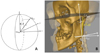
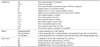
CT scans were obtained by using a spiral CT scanner (Light Speed QX/I, GE Medical Systems, Milwaukee, WI, USA) with 512×512 matrix, 120 kV, 200 mA and gantry angle 0°. The axial image thickness was 2.5 mm, the table speed was 3 mm per second, and the scanning time was 0.8 second. Digital imaging and communication in medicine (DICOM) images were created in 1.0 mm slice thickness. The acquired DICOM data were input into a personal computer. Using the CT data, the 3D images were reconstructed by software, Vworks+Vsurgery (Cybermed, Seoul, Korea). A multiplanar reformatted image, a volumetric model and a surface-rendered model of a CT scan which were completely interfaced on the software were constructed. The landmarks were defined on the volumetric model with the guidance of the multiplanar reformatted image. Three orthogonal reference planes were established: the midsagittal reference plane (yz plane) was made of Cg, ANS and Op;9 the horizontal reference plane (xy plane) was formed perpendicular to the midsagittal reference plane to pass through right Or and left Po;9 the coronal reference plane (zx plane) was made with Dent7 to be perpendicular to both the midsagittal and the horizontal reference planes. Condylar landmarks, gonial landmarks, and menton were identified. The condylar landmarks were the most superior (Cdsup), lateral (Cdlat) and posterior (Cdpost) points of the condylar head. The gonial landmarks were the most inferior (Goinf), lateral (Golat) and posterior (Gopost) points of the gonion area. Menton (Me) was the most inferior point on the mandibular symphysis. The lines, longitude of ramus (LR: Cdsup-Goinf), ramus lateral (RL: Cdlat-Golat), ramus posterior (RP: Cdpost-Gopost) and mandibular body (MB: Gopost-Me) were established with connecting each landmark. The rectangular coordinates (|x|, y, z) were obtained by the measurement tool. |x| was the distance from the midsagittal reference plane, y was the distance from coronal plane, and z was the distance from the horizontal reference plane; |x| was set to an absolute value for our purpose of comparing differences of the deviated side and the opposite side (Table 1, Fig. 1).
Alternate spherical coordinate systems of the facial lines
An alternate spherical coordinate system was developed from the geographic coordinate system for 3D evaluation of the facial lines and facial asymmetry.15
Figure 2 shows the definition of the alternate spherical coordinate system (v, θ, φ) of LR as an example. The three orthogonal axes were drawn, centered at the landmark, Goinf. LR was identified as a vector and its length v was measured. The angle between the midsagittal reference plane and the vector were identified as midsagittal inclination angle, θ. The angle between the coronal plane and the projection line of the vector onto the midsagittal reference plane was identified as coronal inclination angle, φ. The alternate spherical coordinates (v, θ, φ) of other facial lines were made in the same way. The line LR (Cdsup-Goinf) was formed as (xcd-xgo, ycd-ygo, zcd-zgo), where (xcd, ycd, zcd) is for Cdsup and (xgo, ygo, zgo) is for Goinf. If x=xcd-xgo, y=ycd-ygo, and z=zcd-zgo, the alternate spherical coordinates (v, θ, φ) were obtained from the formulae as below: then θ, φ in radian measure were converted into θ, φ in angle (θrad=θ°×π/180; φrad=φ°×π/180).

The bilateral differences of the alternate spherical coordinates (dv, dθ, dφ) between the deviated side and the opposite side was obtained (Fig. 2).
Because the bilateral facial lines have different starting points on the three-dimensional space, it was also necessary to describe the starting point for a definite representation of the vectors. The bilateral difference (dx, dy, dz) of the starting points, Goinf, Golat, Gopost were obtained.
Statistical analysis
The bilateral differences of the spherical polar coordinates of each line (dv, dθ, dφ) were compared between the groups by Mann-Whitney U test. The correlation with chin deviation was statistically analyzed by Spearman's test. The bilateral differences of the landmarks (dx, dy, dz) were statistically compared by Mann-Whitney U test. SPSS 18.0 (SPSS Inc, Chicago, IL, USA) was used for the statistic analysis.
Results
Bilateral difference of the alternate spherical coordinates of facial lines
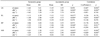
The bilateral differences of lengths of LR, RL, RP and MB were -1.62±3.61 mm, -1.13±6.29 mm, 0.06±4.04 mm and -0.83±2.38 mm in the symmetric group, and -3.45±4.59 mm, -3.12±5.23 mm, -3.26±4.53 mm and -3.15±2.92 mm in the asymmetric group; the facial lines of the deviated side were generally shorter than those of the opposite side. The bilateral differences of lengths of RL and MB were significantly different between the groups (p<0.05). The bilateral differences of midsagittal inclination angles of LR, RL, RP and MB were -1.41±2.46°, -1.48±2.6°, -2.25 ±3.32° and 0.24±2.57° in the symmetric group, and -4.36±3.86°, -4.99±4.15°, -3.84±5.06° and -0.15±2.96° in the asymmetric group; the facial lines of the deviated side were generally more inclined toward the midsagittal plane than those of the opposite side. The bilateral differences of the midsagittal inclination angles of LR, RL, RP and MB were significantly different between the groups (p<0.05). The bilateral differences of coronal inclination angles of LR, RL, RP and MB were -0.42±3.29°, 1.56±10.93°, -0.23±3.98°, -1.65±1.74° in the symmetric group, and -1.28±3.78°, -2.34±11.69°, -3.49±4.03° and -8.06±3.84° in the asymmetric group. The facial lines of the deviated side were generally more inclined toward the coronal plane than those of the opposite side; however, there was no significant difference between the two groups in the bilateral differences of coronal inclination angle of the facial lines.
The differences of the length and midsagittal inclination of LR and MB were significantly correlated with chin deviation (p<0.05). The differences of the midsagittal inclinations of all the lines had significant correlations with chin deviation (p<0.05). The difference of the midsagittal inclination of the MB had a fairly high negative correlation with chin deviation (r=-0.829, p<0.05). LR and RL showed a relatively high negative correlation with chin deviation in the difference of midsagittal inclination (r=-.619, -.674, p<.05). As menton was deviated from the midsagittal reference plane, the bilateral differences of the midsagittal inclinations of LR, RL, RP and MB were negatively increased. The lines of the deviated side were more inclined to the midsagittal reference plane than those of the opposite side. There was no significant correlation of the coronal inclinations to the chin deviation (Table 2).
Bilateral difference of the starting points
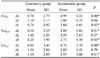
The bilateral differences dx and dz of the landmarks Goinf, Golat and Gopost were significantly different between the two groups (p<0.05). The landmarks of deviated side were significantly more laterally and superiorly to the opposite side in the asymmetric group than in the symmetric group (Table 3).
Discussion
The purpose of this study was to compare asymmetric mandibular prognathism individuals with symmetric mandibular prognathism individuals using a new alternate spherical coordinate system.
A spherical coordinate system is a coordinate system for three-dimensional space where the position of a point is specified by three factors: radius, inclination angle, and azimuth angle.14,15 The spherical coordinate system can be altered and applied for many purposes. In geography, the spherical coordinate system is altered as the geographic coordinate system. The geographical coordinate system, an alternate spherical coordinate system, uses the longitude and latitude, the inclination angle from the equatorial plane and the inclination angle from the meridian to express locations on Earth. The new alternate spherical coordinate in this study was derived from the geographic coordinate system. The length of the vector was measured for each facial line, because the study objects were not spheres of unit radius. The midsagittal inclination angle was defined as the inclination angle from the midsagittal reference plane. The coronal inclination was the inclination angle from the coronal reference plane. In this study, the new alternate spherical coordinate systems of the representing lines of the facial asymmetry were obtained, using the three factors of the lines, length, midsagittal and coronal inclination angles. The facial lines have different starting points. It was also necessary to describe the starting point for a definite position of the lines. The bilateral difference (dx, dy, dz) of the starting points of the lines should be obtained.
In the previous researches, the length and/or inclination of facial lines were evaluated, however only one or two factors of spherical coordinates of the lines were defined.9-13 The 3D characteristics of the facial lines have not been fully explained. Even if two lines share one identical factor, the lines would not be the same if the other factor is different. For example, even if two lines are the same in length, but if the midsagittal or coronal inclination angle is different, the lines are different from each other. Therefore, the three factors of facial lines should be presented to identify the lines.
In this study, the asymmetric group was significantly different from the symmetric group in the length of LR and MB and in the midsagittal inclination of LR, RL, RP and MB. The difference of the lengths of LR and MB had fair correlation with the chin deviation. The differences of the midsagittal inclinations of LR, RL, RP and MB had fair or high correlations with the chin deviation. The bilateral difference of the gonial landmarks was significantly different between the groups. The differences dx and dz of the starting points were statistically and significantly greater in the asymmetric group than in the symmetric group.
In this study, the facial lines evaluated by Hwang et al9 were reilluminated using spherical coordinate system. The spherical coordinate system could be applied to analyze any facial lines.
In conclusion, this study showed that the spherical coordinate system was useful for 3D evaluation of the facial asymmetry using the ability of the spherical coordinates to identify the 3D facial lines by its length and angle inclinations. The alternate spherical coordinate might be useful in the measurements of the lines of interest in orthodontic treatment. In this study, the bilateral differences of lengths of LR, RL and MB and the midsagittal inclination of LR, RL, RP and MB contributed to the facial asymmetry in mandibular prognathism individuals.

 XML Download