

 PDF
PDF ePub
ePub Citation
 Print
Print


Introduction
The term "mesiodens" refers to a supernumerary tooth located between maxillary central incisors.1 Mesiodens is a type of supernumerary tooth that appears most frequently, between 47% and 67% of cases, with a prevalence of 0.15-1.9% in the general population.2-4 Most of the mesiodentes are impacted.4
Asymptomatic unerupted mesiodens may be discovered during a radiological examination of the premaxillary area. Mesiodens may give rise to a variety of complications such as impaction, delayed eruption and ectopic eruption of adjacent teeth, crowding, diastema, axial rotation, radicular resorption of adjacent teeth, and dentigerous cyst.5,6
There are radiographic localization methods for mesiodens such as tube shift technique,7 right angle technique, conventional tomography,8 computed tomography (CT), and cone beam computed tomography (CBCT).1 The tube shift technique is broadly used to verify the location of the mesiodens, however it is impossible to confirm the exact location quantitatively.1 The right angle technique using lateral cephalometric radiograph provides the exact location of the mesiodens, however multiple teeth, especially in the mixed dentition state, can overlap the mesiodens. In this situation, it is difficult to find the mesiodens.1 The CT and CBCT are the most accurate methods to obtain the information of the location in millimeter scale since they provide three dimensional information.6 However, they are expensive and emit high dose radiation. The radiation dose of CBCT is lower than that of conventional CT, however it is higher than that of conventional radiography.9
Panoramic radiography is a curvilinear variant of the conventional tomography. The objects out of the image layer are blurred and magnified or reduced in size. The change of horizontal dimension is more severe than that of vertical dimension. The horizontal magnification ratio increases steeply with the distance from the center of the image layer facing the rotation center.1,10,11 The ratio decreases as the distance toward the film increases. The horizontal change is more severe on the anterior region than on the posterior region.11 Theoretically, it is possible to localize the object if its horizontal magnification ratio in the panoramic radiography is known.
The purpose of this study was to evaluate a new technique for localizing impacted mesiodens using its horizontal magnification ratio on the panoramic radiograph.
Materials and Methods
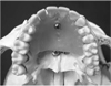
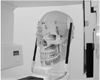
A metal ball of 5 mm diameter was attached along the midline of the palatal region of an artificial skull phantom (3B Scientific, Hamburg, Germany). The ball was fixed with baseplate wax at a location 10 mm posterior to the contact point of the two central incisors (Fig. 1). The crown widths of the right and left central incisors were measured using vernier calipers (Mitutoyo, Kawasaki, Japan), and they measured 7.78 mm and 7.87 mm, respectively. This skull phantom was used to obtain the distance-magnification equation of the panoramic equipment. The metal ball within the phantom was located at the distance of -16, -14, -12, -10, -8, -6, -4, -2, 0, 2, 4, 6, 8, 10, 12, 14, and 16 mm from the center of the image layer (0 mm), respectively, and then panoramic radiographs were obtained using Proline XC (Planmeca, Helsinki, Finland) at 60 kV and 4 mA at the 17 positions according to the manufacturer's instruction except for the anteroposterior location. Therefore a total of 17 radiographs were obtained. To compensate the radiopacity of cervical vertebrae, the 1.5 liter Polyethylene terephthalate (PETE) bottle filled with water was used (Fig. 2). The computed radiography (CR) system (FCR 5000, Fuji, Tokyo, Japan) was used as the imaging system and the images were saved as DICOM files. The horizontal width of the metal ball on the panoramic radiograph was measured using the measuring tool of the system. The measurement was performed on each image twice and the mean value of two separate measurements was used as data. To obtain the magnification ratio according to the location of the ball, the measured ball width was divided by the actual ball width (5 mm). The location-magnification equation was obtained by applying simple regression analysis to the location of ball ranging from -16 mm to 16 mm, and the magnification ratio according to the location.
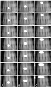
In order to simulate the impacted mesiodens, the same metal ball was fixed at locations 10 (group 1), 15 (group 2), and 20mm(group 3) posterior to the contact point of the central incisors, and 7 panoramic radiographs were obtained for each group at the normal patient position (position 0), 2, 4, and 6 mm anterior to the normal position (position -2, -4, and -6, respectively), and 2, 4, and 6 mm posterior to the normal position (position 2, 4, and 6, respectively) (Figs. 2 and 3). The horizontal crown widths of the right and left central incisors and the metal ball on the panoramic image were measured using measuring device of the CR system and the mean value of two separate measurements was used as data.
Periapical radiographs using paralleling technique were taken on all 3 sets of the skulls mentioned above (10, 15, and 20 mm). Heliodent DS X-ray generator (Sirona, Bensheim, Germany) was used at 60 kV. They were digitized at 600 dpi using film scanner (PowerLook II, UMAX Data System Inc, Taipei, Taiwan). The numbers of the pixels corresponding to the width of central incisors and balls were counted and then were converted to millimeter scale. The average of two separate counting on each image was used as data.
The actual width of the object is essential in calculating the horizontal magnification ratio of panoramic radiograph. The width of a central incisor can be measured directly on the actual tooth or indirectly on the dental model. However, that of an impacted mesiodens cannot be measured, therefore it should be estimated. In this study, three methods were used to obtain the widths of the incisors and the ball, and then the widths were used to calculate the horizontal magnification ratio of the panoramic radiographs.
Three methods were used to obtain the widths of the incisors and the ball; the incisors - measured on the phantom, the ball - calculated considering the magnification ratio of the incisor on the periapical radiograph (Method 1), the incisors - measured on the phantom, the ball - measured on the periapical radiograph (Method 2), both of the incisors and ball - measured on the periapical radiograph (Method 3). These were considered as the actual widths of the incisors and ball.
The distance from the center of the image layer to the incisors and metal ball was calculated by using the distance-magnification equation, and then the distance between the incisor and metal ball was calculated by means of the difference from the center of the image layer. The calculated distance was compared with the actual distance measured on the phantom.
ANOVA for repeated measures was used with the factors for Group (3 groups) and Method (3 methods).
Results
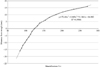
The magnification ratios at locations 16 mm labial and 16 mm palatal from the center of the image layer were 83.8% and 270.3%, respectively. The location-magnification equation obtained was y=0.0000007x3-0.005x2+1.1861x-84.982 (y: distance from the center of the image layer; x: magnification ratio) with R2=0.9986 (Fig. 4).
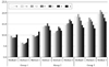
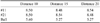
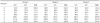
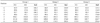
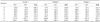
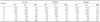
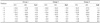
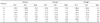
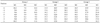
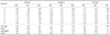
Table 1 shows the widths of the central incisors and the metal ball on the periapical radiographs. Tables 2, 3, and 4 show the horizontal magnification ratio of the incisors and the ball on the panoramic radiographs according to Method 1, 2, and 3, and Tables 5, 6, and 7 show the distance of the incisor and the ball from the center of the image layer. Table 8 and Fig. 5 show the calculated distances between the incisor and the ball. Table 9 shows the differences between the calculated and actual distances. The smallest difference between the calculated and actual distance was 0.1±0.7 mm in Group 1/Method 3. The largest difference was -4.2±1.6 mm in Group 3/Method 2, as shown in Table 9. In all groups, Method 3 was the most accurate. The three groups and three methods were significantly different (P<0.001).
Discussion
The purpose of this study was to evaluate a new technique for localizing impacted mesiodens using horizontal magnification ratio on panoramic and periapical radiograph.
On the panoramic radiograph, vertical magnification ratio can be calculated by dividing the distance from the x-ray source to the film by the distance from the x-ray source to the object. In the horizontal dimension, the rotation center of the beam serves as the functional focus. If the film is stationary, horizontal magnification ratio is always larger than vertical ratio. Instead, the film moves in the same direction as the beam although at a slower speed. Therefore the horizontal magnification ratio is decreased relatively. By carefully choosing the speed of the moving film, it is possible to reduce the horizontal magnification until it just matches the vertical magnification for one particular curved layer which is called the 'image layer'.11 The horizontal magnification ratio changes steeply with distance from the image layer. This is a characteristic of the panoramic radiography and it can be used to localize the mesiodens.
The location-magnification equation obtained was y=0.0000007x3-0.005x2+1.1861x-84.982 (y: distance from the center of the image layer; x: magnification ratio). This is the equation of the panoramic equipment that was used in this study. The equation possibly depends on the location of the film, the image layer, and the rotation center and the speed of the moving film. Therefore it possibly varies according to the equipments.
To localize an impacted mesiodens using the equation, it is essential to know the actual width of it in order to calculate the magnification ratio. It is difficult to know the actual width of it without the aid of CT or CBCT before extraction of the tooth. Therefore the actual width should be estimated. Periapical radiographs were used to estimate the actual width in this study.
The metal ball was not fixed at the labial side in this study because the mesiodens is rarely located labially. If it is located labially, it is easily detectable because of the changed labial contour of alveolar bone. Several studies using CBCT reported that the labial location of mesiodens was 1.2-3.4%.6,12
Among the groups, the result from Group 1 was the most accurate. The farther away from the incisors the metal ball was placed, the less accurate the distance was. Among the Methods, the result from Method 3 was the most accurate. To use Method 1 and 2, the actual widths of the incisors should be known. It is difficult to measure the teeth directly. Method 3 is relatively simple. It uses just the measured widths of the incisors and the ball for the estimated width in the periapical radiograph. Using Method 3, all but one of the differences between calculated and actual distances were under 3 mm. The one over 3mm was the result of the most palatally located metal ball (Group 3) and the most palatally positioned skull phantom (position 6) in this study.
In conclusion, it is possible to localize an impacted mesiodens quantitatively using panoramic and periapical radiographs.
 XML Download