

 PDF
PDF ePub
ePub Citation
 Print
Print


Introduction
Intraoral periapical radiography is a noninvasive diagnostic tool widely used in the clinical practice for assessment of radiographic bone level around teeth or implants. The periapical radiographs with paralleling technique - also known as right angle technique or long cone technique - allow obtaining more accurate records of crestal bone in relation to the tooth root and bone density changes, resulting in a radiographic guidance of teeth in their osseous structures.1
The intraoral paralleling technique has some limitations such as small vertical and horizontal angulations of the X-ray beam with respect to the film, less-defined interproximal area of the cervical portion of the tooth mainly cementoenamel junction, inability to clearly assess the bone defects on buccolingual or palatal surfaces, difficulty in clinical performance, and inexact reproducibility of the technique in further evaluations mainly in posterior teeth. These limitations should be avoided in order to reduce evaluating and diagnostic errors inherent in all periapical radiographs, like poor identification of anatomical landmarks such as root apex and cementoenamel junction, impossibility of evaluation of buccolingual/palatal bone morphology, and distortions of coronal aspect of the tooth.2-8
The differences of parallelism (vertical/horizontal angulations) in radiographic imaging of longitudinal studies originate from the alterations of three-dimensional positioning between the X-ray collimator system/positioner device/X-ray film.6-8 Commercially available devices for intraoral paralleling technique provide perpendicularity between the central ray and the film, however they are not useful in preventing other errors during the clinical performance of the technique.7,8
Therefore, a radiographic device was modified using the radiographic holder Rinn® XCP Instrument Kit (Dentsply, Elgin, IL, USA), in order to maximize the reproducibility of the radiographic paralleling technique modified by Kugelberg and to minimize the errors, resulting on the calibrated and superimposable digital radiographic images.6,7,9
Materials and Methods
Periapical radiographs were taken at the posterior area of the patients submitted to mandibular third molar (3 Mm) surgical extraction employing a modification of the radiographic technique verified by Kugelberg et al in 1986.9 The extracted 3 Mms were fully impacted without contact with the oral cavity and in close relation with the distal aspect of mandibular second molar (2Mm)(Type II/III, B/C of the Pell and Gregory classification10 and in mesioangular, horizontal or vertical positions of the Winter classification11).
The patients were radiographed with a photostimulable phosphor (PSP) plate (31×41 mm, Digora® OPTIME, Soredex Orion Corporation, Helsinki, Finland) and intraoral radiographic equipment (Philips Oralix 65, Philips, Eindhoven, The Netherlands) set at 65 kVp, 7.5 mA, and 0.2 seconds. The implemented radiographic technique was paralleling technique focusing the central ray on the center of the crown of their 2 Mm. The focus-to-object distance was about 20 cm using an X-ray film positioner for posterior region (Rinn® XCP Instrument Kit, Dentsply, Elgin, IL, USA), consisting of a ring, an arm and a bite-block. The PSP plates were scanned with Digora® OPTIME scanner, and then the images were saved.
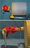
For the achievement of reproducibility in the radiographic technique, there were essential factors including the stability of the X-ray collimator/positioner (positioning device) for intraoral radiography/PSP plate at the space planes: the vertical plane or parallel to the longitudinal axis of the 2 Mm, the horizontal plane or occlusal and buccolingual plane.2-4,7 To ensure the stability in the space planes, an additional device was fabricated with modification of the commercial film positioner Rinn® XCP Instrument Kit, in the form of a hollow cylinder adapted to the positioner and the collimator, so that it was attached to the collimator of the X-ray machine to prevent unwanted movements and undesirable angulations.
In addition, a biteblock of the positioner was individualized for each patient with acrylic resin (Pattern Resin®, GC America Inc., Alsip, IL, USA) at the 2 Mm in maximum intercuspal position in order to ensure the reproducibility of the radiographic technique in the occlusal plane. In this way, the PSP plate was centered and parallel to the longitudinal axis of the 2 Mm, in a reproducible position and perpendicular to the horizontal (occlusal) plan (Fig. 1).
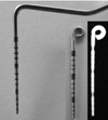
A specific X-ray gauge pin was used for assessment of bone defects distal to the 2 Mm after impacted 3 Mm surgery.9 This gauge pin consisted of an active tip of a conventional probe (PCP-UNC 15®, Hu-Friedy, Chicago, IL, USA) of 15 mm in length, to allow the maximum intercuspal bite with customized biteblock constructed in acrylic resin. This probe was chosen for having millimeter indentations visible radiographically to measure directly the bone defects and to obtain a conversion scale depending on the radiographic processing and computerized measuring system used. Another peculiarity of this gauge pin was a hook at its end to tie dental floss in order to avoid swallowing (Fig. 2). Prior to taking each radiograph, the millimetric gauge pin was inserted into the same probing point through the small hole of the biteblock. Therefore, it allowed comparing the different images taken at the different times after surgery, verifying the reproducibility of three-dimensional geometric relationship.
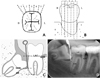
The probing depth of gingival sulcus was measured at the distal aspect of 2 Mm in five equidistant points and selected the deepest probing depth point. The reference pin was inserted at this point to perform the X-ray evaluations and to determine the bone level on the pre- and post-operative radiographs. Figure 3 shows the radiographic image made with this technique with the anatomic reference points used to measure the linear radiographic distances.
All radiographs were taken prior to the extraction of the 3 Mm and after the surgery between 3 and 12 months. This evaluation period was considered appropriate, with repeated assessments, to visualize any radiographic changes and analyze the reproducibility of the radiographic technique. The anatomical reference points and the tip of the gauge pin were recorded with a side by side comparison of the initial and final posterior periapical radiographs. The pre and post-operative radiographs were compared at the same time.
Results
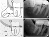
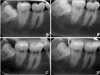
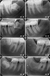
The pre and post-operative radiographs showed no difference in the records of the anatomical reference points and the tip of the gauge, thus the technique could be used for the longitudinal evaluations of the alveolar bone status (Fig. 4). This technique provided a better maintenance of the same geometric position in space compared with the conventional intraoral paralleling technique (Fig. 5). In addition, the insertion of a gauge pin always marked the same reference point and localized the deepest portion of the osseous defect on the 2-dimensional radiographs (Fig. 5D). Also, their millimetric indentations allowed the direct adjustments of distortions between the repeated radiographs in the longitudinal evaluations and the direct measurement of the osseous defects. Figure 6 shows a case (2 right and 2 left sides of the mouth) employing this method to measure the radiographic bone changes on the distal aspect of 2 Mm after extraction of the 3 Mm.
Discussion
The radiographs are the only universally available non-invasive method of visualizing the osseous component of the periodontium in vivo.12
Duckworth et al established some desirable criteria for standardization of intraoral radiographs such as: the method should use readily available materials, should not be uncomfortable for the patient, should not require extensive training for use, and should provide information about the degree of standardization. The ionizing radiation should be exposed minimally with appropriate image quality to provide diagnostic information, and the projection should minimize the distortion of the anatomic structures of interest.12
A lot of techniques for radiographic standardization procedures had been described using different X-ray devices, and adaptations, to meet the ideal radiographic criteria resulting in the accurate diagnosis.12-16 Our technique was similar to those techniques referred above using a radiographic device with an occlusal registration for geometric standardization. Additionally, we complemented the technique with the introduction of the gauge pin, as utilized by Kugelberg et al,9 allowing easy calibration between the different radiographs and knowing the angulation error between them. As a result, we could compare quantitatively the radiographic images taken at the different times after surgery, verify the reproducibility of three-dimensional geometric relationship and consequently, determine the same reference points, and measure the bone defects with a minor error. It also permitted an easy comparison side by side, analyzing the radiographs at the same moment, the direct measurement in millimeters of osseous defects, and comparing the techniques in the measurement of bone height and the percentages of root length or tooth length.17,18 Through the determination of depth of the distal aspect of 2 Mm, by the insertion of the millimetric gauge pin into the same probing point selected prior to the surgery (point of lowest bone probe), the deepest portion of the bone defect was verified regardless of the type of defect. The bone level determination was precisely identified with this pin on the two-dimensional radiographs. The values obtained from the direct digital measurement of alveolar crestal bone or length of bone defects should be analyzed with caution because the radiographic assessment underestimated bone level as compared to real measurements.5,17,19-21
According to Jeffcoat et al, our technique accorded with the requirements for resolution, readability, and accuracy in relation to specific periodontal radiographic tasks. Our method permitted to obtain the standardized periapical radiographs with a moderate to high resolution, repeatability, and accuracy, and the screening detection between 0.5 to 1 mm of bone changes22 even though digital subtraction radiography would provide the higher accuracy and repeatability in detecting small bony changes on the serial standardized radiography.23-26
This technique offers other advantages such as low cost with low ionizing radiation because the material is relatively accessible in daily clinical practice, compared with other radiological techniques like a computed tomography. As a result, this method has clinical applicability without any other big technological resources.
As disadvantages, we can include the need of 4-hand work and the difficulty to perform clinically. It is a laborious technique (the need of confection of the biteblock positioner individualized for each patient with acrylic resin), with much time consuming. It was verified a slow adapting curve which means more time to reach accuracy. Also, the patient's cooperation during the technical performance due to the discomfort of the procedure is necessary. This last disadvantage could be obviated if the use of the technique would be performed in anterior areas of the oral cavity. This technique can be difficult to adapt in posterior area due to gag reflex and discomfort. Some patients have a difficulty in biting caused by the bulky bite block and the length of the gauge pin. The positioning and stability of the bite-block with maintenance of the vertical position of the gauge pin is, as well, difficult in the posterior areas. This method is also difficult to apply in patients with temporomandibular joint pathology or limitation of mouth opening.
This technique can be used for a rigorous evaluation of radiographic bone defects on two-dimensional radiographs. It can be used in clinical and research applications, mainly in the longitudinal monitoring of bone healing or in the osseous regeneration along the time. It can be utilized in all areas of the mouth, being more difficult in the posterior areas compared with the anterior ones.
This method can be applied in other fields of dentistry (oral surgery, implantology, endodontics, periodontics, etc) which need longitudinal evaluation using the serially acquired radiographs. This procedure can be used in all localizations of the oral cavity using the appropriate intraoral alignment system.
In the future, it is necessary to perform a study which quantifies the error, repeatability, distortion of the radiograph (calculating vertical and horizontal angulations), and estimation of the differences between different examiners. It is also required to compare the radiographic measurements with the gold standard (surgical evaluation) and it is needed to apply it in other areas in the oral cavity with comparing the results within different locations.
 XML Download