

 PDF
PDF ePub
ePub Citation
 Print
Print


Abstract
Purpose
The aim of this study is to evaluate the influence of entrance length into computational fluid dynamics (CFD), for distal internal carotid artery (ICA) aneurysms.
Materials and Methods
Two different solutions were used: Siemens prototype software (SW; prototype, not commercially available) and the package of commer-cial CFD SW (commercials). Twelve models of aneurysm at the distal ICA were ob-tained from three dimensional angiography. The original models had longer en-trance lengths from the cervical segment of ICA, whereas intracranial (IC) model lengths were shorter from the proximal cavernous ICA.
Results
The prototype showed faster flow than the commercial CFD, when comparing the maximum value on a velocity scale. Visualization of pathline within the aneu-rysm sac was seen well by the prototype, except one original model which showed a pathline leak. With IC models, both tools showed high correlation with the flow velocity.
REFERENCES
1.Robertson AM., Watton PN. Computational fluid dynamics in aneurysm research: critical reflections, future directions. AJNR Am J Neuroradiol. 2012. 33:992–995.

2.Li MH., Chen SW., Li YD., Chen YC., Cheng YS., Hu DJ, et al. Prevalence of unruptured cerebral aneurysms in Chinese adults aged 35 to 75 years: a cross-sectional study. Ann In-tern Med. 2013. 159:514–521.
3.D'Urso PI., Lanzino G., Cloft HJ., Kallmes DF. Flow diversion for intracranial aneurysms: a review. Stroke. 2011. 42:2363–2368.
4.Moyle KR., Antiga L., Steinman DA. Inlet conditions for im-age-based CFD models of the carotid bifurcation: is it rea-sonable to assume fully developed flow? J Biomech Eng. 2006. 128:371–379.
5.Hoi Y., Wasserman BA., Lakatta EG., Steinman DA. Effect of common carotid artery inlet length on normal carotid bi-furcation hemodynamics. J Biomech Eng. 2010. 132:121008.
6.Hodis S., Kargar S., Kallmes DF., Dragomir-Daescu D. Artery length sensitivity in patient-specific cerebral aneurysm simulations. AJNR Am J Neuroradiol. 2015. 36:737–743.
7.Cebral JR., Castro MA., Appanaboyina S., Putman CM., Millan D., Frangi AF. Efficient pipeline for image-based patient-specif-ic analysis of cerebral aneurysm hemodynamics: technique and sensitivity. IEEE Trans Med Imaging. 2005. 24:457–467.
8.Hodis S., Kallmes DF., Dragomir-Daescu D. Adaptive grid gen-eration in a patient-specific cerebral aneurysm. Phys Rev E Stat Nonlin Soft Matter Phys. 2013. 88:052720.
9.Jansen IG., Schneiders JJ., Potters WV., van Ooij P., van den Berg R., van Bavel E, et al. Generalized versus patient-specif-ic inflow boundary conditions in computational fluid dy-namics simulations of cerebral aneurysmal hemodynamics. AJNR Am J Neuroradiol. 2014. 35:1543–1548.
Fig. 1.
Case 2. Segmentation and mesh generation. Prototype (A–D) and commercials (E, F). A. Virtual rendering shows small vessels. B. Model generation with surface triangular mesh after removing small vessels. C. Original model: model processing by adding cutting planes (arrows) and defining them as inlet or outlets. Note the in-equilateral triangles (yellow box) at inlet. D. Making IC model from original model. New inlet of IC model is made by adding cutting plane at the ascending cavernous segment of internal carotid artery. E. Imported model from prototype shows non-circular shape of outlet and in-equilateral triangles (arrowhead). F. After re-meshing, model has circular outlet (yellow, arrowheads) and even shaped triangles. IC = intracranial
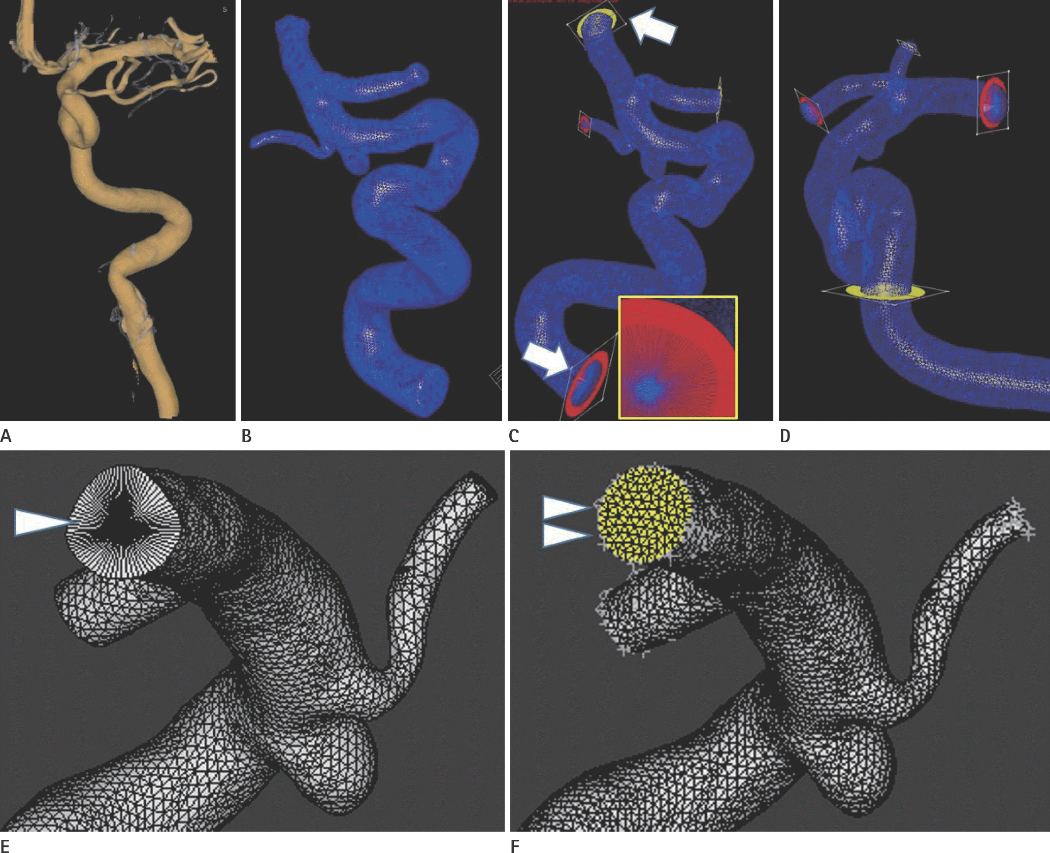
Fig. 2.
Case 3. Flowchart to make and determine the maximum value on velocity scale. A. With commercials, cutting line (arrow) was selected at outlet and is perpendicular to axis of the vessel. Cutting plan image (lower) has velocity scale and Cartesian coordinate system. B. With prototype, cutting plane (left lower) was made by moving axis (arrowheads) in other two multiplanar reconstruction window (upper left and upper right).
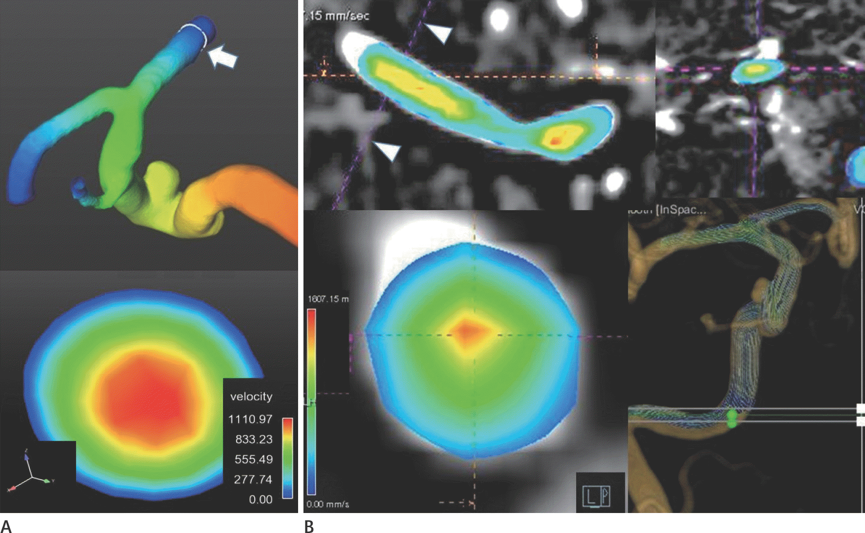
Fig. 3.
Case 11. Capture images of pathline animation. A. Commercials with original model. B. Commercials with intracranial (IC) model. C. Prototype with original. D. Prototype with IC model. More pathlines are visible within the aneurysm sac on prototype, especially IC model. Clear vessel images overlap with the pathline on commercials. Non-segmented vessel image overlaps with the pathline on original model by prototype. No overlapped vessel image of IC one by prototype. The grading of pathline filling were 2 on commercial and 3 by prototype at each model.
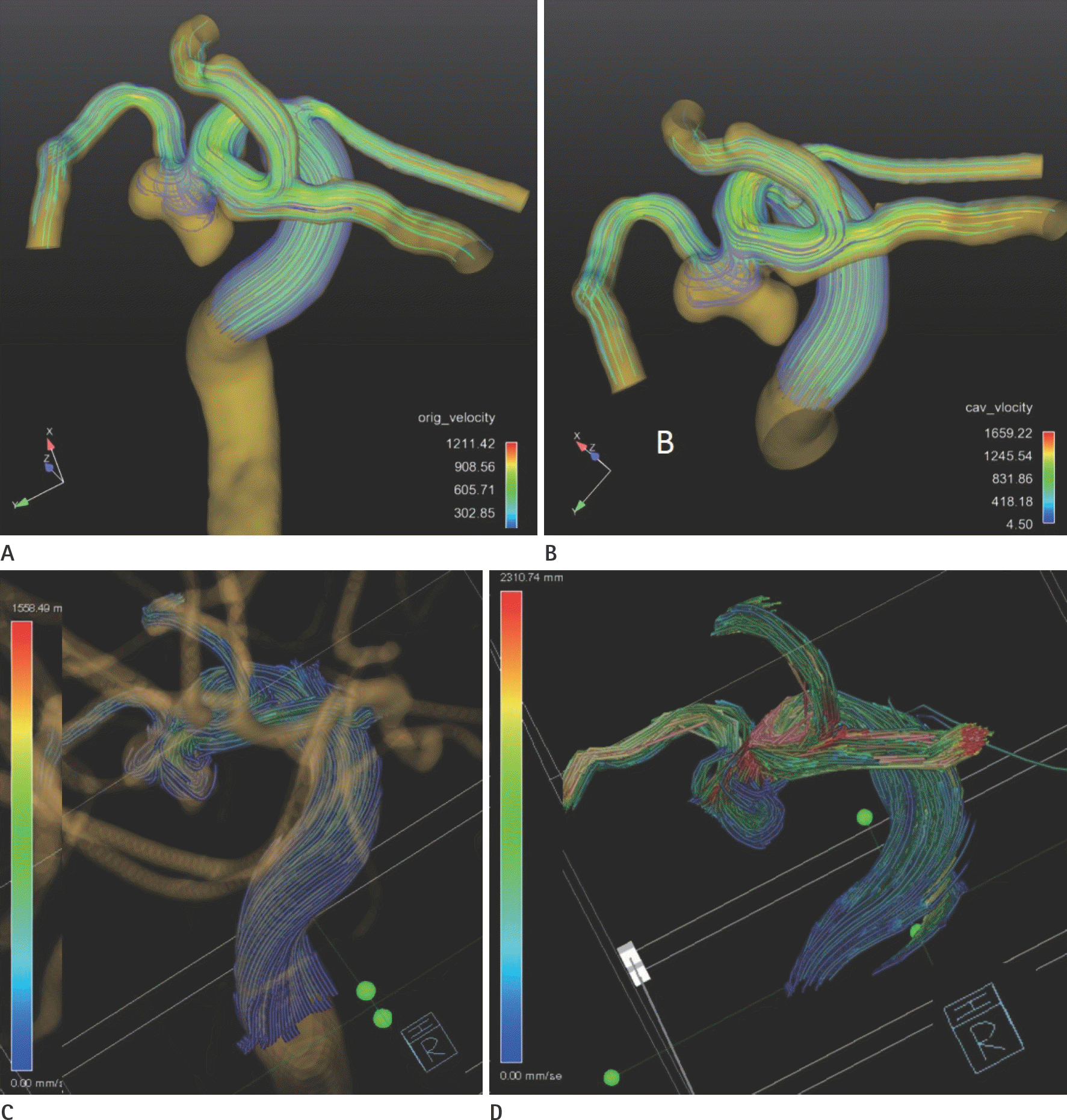
Fig. 4.
Case 7. 3D virtual rendering image (A) shows kissing artifact (arrowheads) between aneurysm sac and adjacent internal carotid artery (ICA). After removing the artifact by punching tool, 3D surface mesh (B) does not show kissing artifact. Leaking artifact (arrows) is noted on both original (C) and intracranial (IC) model (D). Indeed, pathline filling is poorer than the commercial (not shown) on original model contrast to IC model. Note that no leak between the proximal of ophthalmic artery and adjacent ICA (double arrowheads, A) after the punch out the kissing artifact.
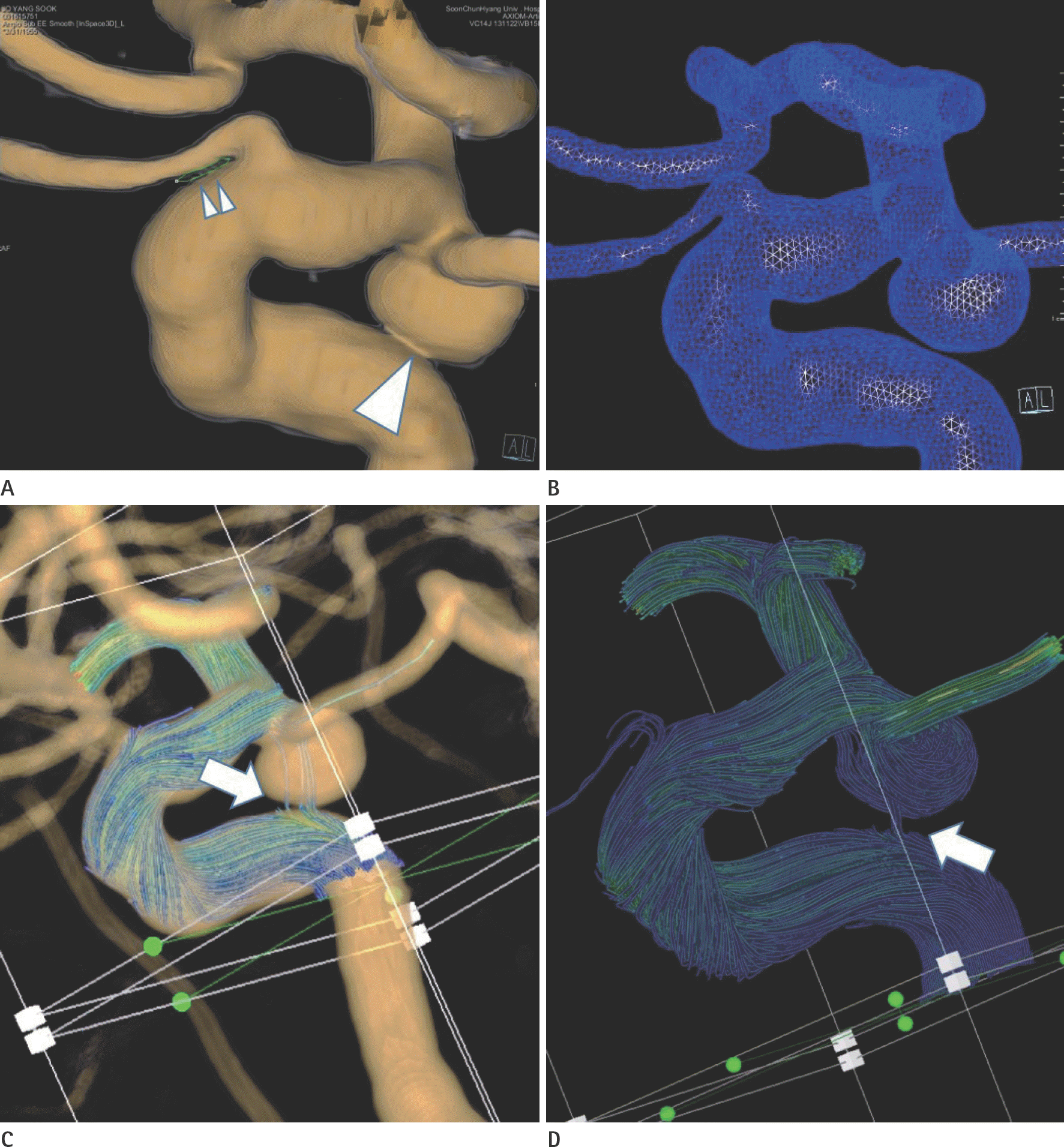
Table 1.
Comparison of Flow Velocities and Pathline Visualizations between Two Models and Solvers
Grade 0 = none, grade 1 = < 1/3, grade 2 = 1/3–2/3, grade3 = > 2/3 of sac C = commercials, IC = intracranial model, MV = maximum value on veloci-ty scale (mm/sec), Org = original model, P = Siemens prototype, PF = path-line filling within aneurysm sac, PL = pathline leak which noted only on pro-totype, Size = size of aneurysm (mm)
 XML Download