

 PDF
PDF ePub
ePub Citation
 Print
Print


INTRODUCTION
Anchorage is the source of resistance to the forces that are generated in reaction to the active component of an appliance, and it plays a very important role in orthodontic treatment [1]. Recently, various skeletal anchorage systems including endosseous implants, mini-implants, and mini-plates have entered into clinical use. Among them, mini-implants (MIs, also known as temporary anchorage devices) are most frequently used due to their ease of installation [2].
The successful installation of MIs is influenced by the skeletal pattern of the patient, immediate or late loading, oral hygiene, and the shape of the MI [3,4], and success rates ranging from 84% to over 90% have been reported in several studies [5,6]. While MIs are very similar to dental implants, they are different in that some MIs do not exhibit osseointegration with the surrounding bone. Therefore, the primary stability of an MI, also known as its initial stability, is more important for the successful installation of MIs than it is for the installation of dental implants.
The primary stability of an MI is achieved by mechanical coherence between the bone and the MI immediately after installation, while secondary stability is achieved after healing, by means of a process in which osteoblasts form fibrous and lamellar bone around the inserted MI. The factors affecting primary stability are bone density, surgical technique, and the morphology of the MI [7,8,9,10], which have also been studied in the context of dental implants [11,12,13]. After a certain period of healing, secondary stability plays a more important role. The transition process between primary and secondary stability is critical, because anchorage stability depends on the completion of bone remodeling. Studies investigating primary stability have mainly dealt with macroscopic and clinical factors; however, little is known about the relationship between macroscopic factors and histologic reactions. There are a limited number of studies which have suggested that microcracks and microdamage are the factors affecting the primary stability of MIs [10,14] Furthermore, microcracks play an important role in bone physiology because they induce remodeling of the cortical bone [15,16,17]. Therefore, the quantification of microcracks, along with bone mass measurements, has been suggested to be a useful technique in then experimentally estimation of the degree of bone remodeling [18].
A relationship between the diameter of an MI and the emergence of microcracks after installation has been reported in previous studies, although no consensus has been reached. Other studies have demonstrated different dynamics of microcrack generation in a range of installation methods including self-drilling, self-tapping, and pilot drilling installation [19,20].
Although MIs are widely used, the effect of microcracks on primary stability is still insufficiently studied. Moreover, to the best of our knowledge, no studies have investigated how microcracks generated during the installation procedure heal. The purpose of this study was to investigate the histomorphometric characteristics of the healing process of microcracks in the cortical bone after the installation of MIs.
MATERIALS AND METHODS
Twelve mature New Zealand white rabbits (males; mean age, six months; mean weight, 3.1 kg) were used according to a protocol that was approved by the Animal Ethics Committee of Seoul National University (SNU-100831-1).
Cylindrically shaped self-drilling MIs (titanium-aluminum-vanadium alloy; Biomaterials Korea, Seoul, Korea), 1.5 mm in diameter and 6 mm in length, were used (total number of MIs=48). In order to exclude the possible effect of extraneous factors on microcrack formation, the design, diameter, and length of the MIs were identical and a single company was used.
All rabbits were randomly assigned to one of four groups, using a round-robin method [21]: the immediate sacrifice group, the one-week healing group, the two-week healing group, and the four-week healing group. Four MIs were placed in the tibia of each rabbit.
The rabbits were anesthetized and an operation field was prepared on the medial side of the upper portion of the hind leg by shaving the fur and disinfecting the area with povidone iodine. Local anesthesia was performed with 2% lidocaine hydrochloride and 1:100,000 epinephrine (Gwangmyung, Seoul, Korea). After a full-thickness stab incision was made on the target site in the proximal third of the tibia, an MI was placed on the site via a surgical device (Elcomed SA-200C, W&H Dentalwerk, Bürmoos, Austria). The insertion settings involved a maximum torque of 30 cN and 20 rpm. Two MIs were placed on each side, with a minimum distance of 2 cm between them. After the operation, all rabbits were administered antibiotics and anti-inflammatory medication. The rabbits were sacrificed at zero days (group A), one week (group B), two weeks (group C), and four weeks (group D) after surgery. Two 2-cm long bone segments containing the MIs were cut from each tibia. Each specimen contained one MI in the central region. However, two rabbits were lost during the healing period and three specimens were abandoned during the harvesting procedure because of spontaneous fracture. In order to prevent additional microcracks during the removal of the MI, specimens were prepared with the MIs in situ. Subsequently, the cortical bone thickness adjacent to the MI was measured using micro-computed tomography (1072 X-ray microtomography, Skyscan, Antwerp, Belgium) and a computed tomography analyzer (version 16.1, Skyscan, Antwerp, Belgium). The bone density of each specimen, expressed in Hounsfield units, was examined to see whether it was between 1,200 and 1,600 [22], which is known to be the normal human range; rabbits have similar cortical bone density values to humans [23].
The blocks were fixed with 4% paraformaldehyde for three weeks, dehydrated with gradient alcohol (90%, 90%, 95%, and 100% alcohol for one day each) and embedded in Kleer set resin TM (Metprep Ltd., Coventry, UK). They were then sliced. The specimens were ground perpendicular to the MI to a thickness of 40-50 µm using the EXAKT cutting and grinding system (EXAKT Apparatebau, Norderstedt, Hamburg, Germany) and stained with hematoxylin and eosin (H&E). Ten consecutive sections were prepared for each specimen and the middle two sections were selected for observation.
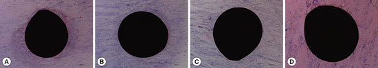
Histomorphologic and histomorphometric observations were performed using a microscope and Image J software (version 1.49a, National Institutes of Health, Bethesda, Maryland, USA). The total number of cracks (NCr, reflecting the number of cracks at least 50 µm long) and the cumulative length of the cracks (CLCr) were measured using a protocol described in a previous study [10] (Fig. 1).
Differences in mean values among the four groups were compared using the Kruskal-Wallis test and the Mann-Whitney U test with the Bonferroni correction, in order to investigate changes in the microcracks depending on the length of healing.
RESULTS
Histomorphologic analysis
As visualized by H&E staining, microcracks were radially or concentrically aligned in the peri-MI bone area. Microdamage was mainly seen in two opposite sides that formed an axis, and was rarely found in the other two areas perpendicular to that axis. Although it was not reliably distinguishable, diffuse damage appeared to be found in the peri-MI bone and linear microcracks seemed to propagate from the surface of the MI. The linear microcracks had various lengths, and some of them even originated at some distance from the surface of the MI. Many ruptured osteocyte lacunae could be found adjacent to the MI (Fig. 2).
Although no distinguishable difference was found between groups B and C, long linear microcracks were found to disappear as the healing process continued from zero to four weeks after the surgery. When groups A and B were compared, concentrically aligned microcracks were found to have undergone a significant decrease prior to the radially aligned microcracks. A decrease in the radially aligned microcracks was noted in groups C and D, in comparison with groups A and B. It was also noted that microcracks starting from the surface of the MI was more hardly found in group D than in group A (Fig. 2).
Histomorphometric analysis
All specimens showed values of bone density within the normal range, between 1,200 and 1,600 Hounsfield units (data not shown). No significant differences were found in the thickness of the cortical bone among the four groups (Table 1).
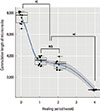
The CLCr tended to decrease as the healing time increased, although a statistically significant difference was not found between groups B and C (P=0.129). However, statistically significant decreases in the CLCr were found between groups A and B and between groups C and D (P<0.001) (Table 2 and Fig. 3).
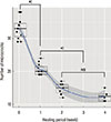
However, the NCr showed a different pattern of change. A statistically significant decrease in the NCr was observed as the healing time increased from zero to two weeks (i.e., among groups A, B, and C; P<0.001), but no significant change in the NCr was found after two weeks (i.e., between groups C and D, P=0.036) (Table 3 and Fig. 4).
DISCUSSION
Although microdamage due to fatigue stress in normal cortical bone or after the installation of cortical bone screws or dental implants has been well studied by many researchers [24,25,26], little is known about microdamage after the installation of MIs. Furthermore, little is known about the repair or healing of microdamage induced by cortical bone screws, dental implants, and MIs. A limited number of studies have performed histomorphometric analysis on the microdamage around MIs; however, most of these studies analyzed microdamage immediately after the installation, evaluated the effects of MI design or different pre-drilling procedures, and mainly dealt with bone-to implant contact [7,10,19,27,28]. In one of these studies, the researches took direct histomorphometric measurements of the microdamage as the healing period progressed and found that four weeks of healing were necessary for the microdamage to be repaired [29]. However, that study dealt with cortical bone screws installed after a pre-drilling procedure, which is more common in orthopedic surgery than in orthodontic treatments. In this study, microdamage around self-drilling MIs without a pre-drilling procedure was observed histomorphometrically, with a focus on the effect of the duration of the healing period. Direct measurements of the microcracks were used for histomorphometric analysis because doing so is a more intuitive way of assessing primary stability than measuring the formation of osteoclasts, osteoblasts, or new bone.
The gross pattern of microcracks showed both concentric and radial alignment, unlike what has been reported in previous studies [19,29]. This discrepancy occurred primarily because the sections were viewed differently. The cross-section which was perpendicular to the long axis of the MI was used for analysis in this study, whereas the sagittal section that runs parallel to the long axis of the MI was used in other studies. Concentrically aligned microcracks cannot be observed in sagittal specimens, due to their orientation. Although it would be better to examine the specimen along the long axis of the MI in order to observe bone-to-implant contact or histologic reactions in the cancellous bone, specimens perpendicular to the long axis of the MI better illustrate microcracks in the peri-MI cortical bone and their repair.
Concentric microcracks were most frequently observed in group A. During the installation procedure of self-drilling MIs, large concentric microcracks are quickly formed due to the release of high torque energy, causing the rupture of microstructures in the osteonal cortical bone. These microcracks seemed to be more destructive than radial microcracks. However, the concentric microcracks were reduced in number after only one week of healing (group B), while the radial microcracks were still prominent after the same healing period. It appeared that the healing process repaired the more destructive concentric microcracks before repairing the less destructive radial microcracks. Concentric microcracks were barely observable in the specimens after four weeks of healing (group D). Some previous studies have described the repair of microcracks after four weeks [27,28,29]. Since a consensus exists that rupture of the osteocyte lacunae and canaliculi is essential for the repair of microdamage [30,31], the concentric microcracks were more prone to be repaired than the radial microcracks because they destroyed the microstructure of osteons in the cortical bone to a greater extent than the radial microcracks.
As a result of the prominent repair of the concentric microcracks, the CLCr showed a statistically significant decrease after one week. A plateau of sorts in the CLCr occurred between one and two weeks of healing (groups B and C). During that period, the differentiation of osteoblasts and the formation of new bone seemed to occur, but no significant change in the CLCr was observed. The repair process starts with the recruitment of osteoclasts at the focal site of the microcrack, forming a resorptive cutting cavity, and is followed by the emergence of a closed cavity with osteoblasts and new bone [32]. After four weeks, the microcracks were replaced by new bone, and the CLCr showed another significant decrease (Fig. 2, 3).
The NCr showed a different pattern of changes than the CLCr. The NCr was significantly reduced by two weeks after the beginning of the healing process and did not change significantly thereafter (groups C and D). During the repair process of the microcracks, the repair foci of the osteoclasts and osteoblasts on the microcracks segmented large linear microcracks into small microcracks [33,34]. The repair process yielded more segments of microcracks after a certain period of healing (two weeks in this study), because large linear microcracks fragmented into several small microcracks, which were countable separately, and therefore no difference was found in the NCr between groups C and D. This explanation is also supported by the observation that the number of microcracks that originated away from the surface of the MI increased after two weeks of healing (groups C and D) (Fig. 2, 4).
Repair process seemed to occur first in large microcracks ahead of minor microcracks by a mechanism that began with the rupture of osteocyte lacunae. Microdamage away from the installation site needed more time to be repaired due to the absence of an initiation event like that observed in the peri-MI area.
In conclusion, the stability of MIs can be enhanced by ensuring a healing period after installation and allowing the repair of microdamage, which would improve primary stability.
Further studies are required to investigate the possible influence of other parameters such as MI design, self-tapping installation, wobbling during installation, and immediate loading. It is also necessary to investigate the correlation between mechanical stability and histologic findings with regard to the healing of microdamage.


 XML Download