

 PDF
PDF ePub
ePub Citation
 Print
Print


INTRODUCTION
Correct positioning of acetabular and femoral components plays an important role in postoperative outcomes following total hip arthroplasty (THA). Malposition of the implant can, in the short term, be a direct cause of dislocation leading to an impingement of the implant, and, in the long term, can impact wear and breakage of the liner and stability of the implant.
The characteristics of Asian patients (e.g., their specific anatomies and lifestyles, daily routines requiring a particularly large range of motion (ROM), and large proportion of young patients) differ from those of Western patients. Therefore, in the Asian population, it is crucial to perform accurate positioning of the implants for reducing the wear and preventing impingement following THA1).
However, it is difficult to achieve accurate positioning of implants and assess the numerical value of implant positioning in THA using conventional methods2). Callanan et al.3) have reported that only about 50% of implants were within an acceptable safe range in conventional THA and hip resurfacing. Errors in positioning occur more frequently in the acetabular component, because the position of the pelvis including the acetabulum is influenced by the longitudinal axis of the spine and body4).
Because bone does not change shape and is distinctly differentiated from soft tissues, accurate images can be obtained using X-ray, fluoroscopy and computed tomography (CT). Moreover, three-dimensional (3D) reconstruction of bones can be easily acquired and a preoperative plan and intraoperative findings can be exactly matched. Therefore, bone is likely the most appropriate tissue for applying computer-assisted surgery. In this respect, computer-assisted orthopaedic surgery (CAOS) has been applied in various fields of orthopaedics since it was first introduced in the late 1980s. The development of CAOS has enabled more accurate implant positioning in THA and this technique is used in basic research related with biomechatronics.
This article aims to describe the evolution of computer-assisted THA and relevant applications.
SPECIFIC CONSIDERATIONS FOR COMPUTER-ASSISTED THA
1. Influence of Pelvic Tilt on Cup Positioning
Without considering the functional pelvic orientation, Lewinnek's method is not an accurate method for cup positioning and assessment. DiGioia et al.5) found substantial variations in pelvic orientation depending on positioning (e.g., standing vs. sitting) using the anterior pelvic plane (APP) on lateral pelvic radiographs; however, they did not assess the change of acetabular anteversion. According to Lembeck et al.6), pelvic reclination of 1° will lead to functional anteversion of the cup by approximately 0.7°. They concluded that pelvic tilt makes navigation systems referring to the APP inaccurate. In Babisch et al.'s study7), the preoperative to postoperative change in supine tilt was a mean of 0.04° posterior in 10 patients with coxarthrosis, 2.5° anterior in 30 patients with dysplasia, and 1.9° anterior in all patients (dysplasia in 75% of patients). Authors who studied pelvic motion concluded that pelvic tilt should be considered when implanting an acetabular component and a constant anteversion angle should not be selected.
Functional pelvic orientation is dependent on the spinopelvic axis. Moreover, because anteversion of the acetabulum is dynamically changing according to pelvic tilt, it is important to define the functional pelvic orientation. However, the change in functional pelvic orientation and the effect of a fixed pelvis from standing to sitting in patients undergoing THA are not well defined. With CAOS for THA, functional pelvic plane (FPP), a true coronal plane in supine and standing positions, can be used as the reference pelvic plane7). Sugano8) recommended to use a FPP where the pelvis in supine on the CT scan table is axially rotated until the bilateral anterior superior iliac spines (ASIS) touches the same horizontal plane, and the inter-teardrop line is then used as the mediolateral axis. Pelvic tilt varies up to 30° or even 60° between individuals as reported by several authors but is relatively constant for one individual4). Babisch et al.7) reported that the range of pelvic movement between the supine and standing positions did not exceed 10° in 83% of the hips. Nishihara et al.9) reported that the difference in the preoperative pelvic flexion angle between the supine and standing positions was 10° or less in 90% of the cases.
2. Influence of Spine on Pelvic Tilt
The mobility and deformity of spine influence on the change in sagittal pelvic tilt between supine, sitting and standing positions1011). Ranawat et al.10) concluded in their study that there was a significant change in sagittal pelvic tilt from standing to sitting, especially in patients with a flexible spine, in which the functional anteversion increases with sitting. The patients with a fixed pelvis had significantly less preoperative sagittal pelvic tilt angle in standing (less anteversion) with less posterior sagittal tilt in sitting, which should be incorporated in cup positioning. Tamura et al.12) reported that presence of compression fractures, age, presence of lumbar spondylolisthesis and small S1 anterior tilt angle were independently associated with posterior change in pelvic sagittal inclination from supine to standing position in patients before THA. Esposito et al.13) concluded in their research that the mechanism by which patients with degenerative disc disease of the lumbar spine achieve sitting differs from those without spine arthrosis with less spine flexion and more femoroacetabular flexion. Generally, pelvic posterior tilt increases when people become old because of the loss of lumbar lordosis, flexion contracture of the knee, and weakness of the back muscle and others14). Suzuki et al.11) described that in older patients with a small preoperative lumbar lordotic angle, the reference pelvic plane should be set more posteriorly than the pelvic plane in the preoperative supine position, and cup anteversion should be reduced by several degrees in order to account for posterior changes in pelvic tilt that will occur after THA. When planning THA for patients with spine deformity and stiffness, preoperative consideration of the posterior change in pelvic tilt after THA should be considered in order to prevent postoperative complications including implant impingement.
3. Concept of Combined Anteversion
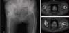
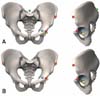
The concept of combined anteversion (CA) is to position the acetabular and femoral components in a relatively safe zone for impingement-free range of motion15). First, the femur is prepared, and next the cup anteversion is adjusted in accordance with the achieved stem anteversion. Because femoral anteversion on the right and left sides of an individual can be significantly different, each side needs to be evaluated separately to accurately apply CA in THA (Fig. 1). Komeno et al.16) have reported that the sum of cup and stem anteversion in posterior dislocated hips was significantly less than in non-dislocated hips and the sum in anterior dislocated hips was significantly greater than that in non-dislocated hips. Several other authors also have stated the importance of CA171819). The safe zone of CA was defined differently by various authors. Ranawat and Maynard18) proposed a CA of 20° to 30° in males and approximately 45° in females. Sendtner et al.20) recommended a CA of 25° to 45°, Barrack21) suggested anteversion of 10° to 20° of both the stem and cup and Dorr et al.17) proposed the mean CA of 35°, ranging between 25° to 50°. Widmer and Zurfluh19) suggested a linear equation, cup anteversion+(0.7×stem anteversion)=37.3° to calculate CA through a finite element analysis. The benefits of using CAOS in THA include the feasibility of applying the concept of CA in implant positioning and acquiring accurate implant placement by confirming implant position based on intraoperative and real-time numerical quantifications of the anteversion of the acetabular cup and femoral stem. Stefl et al.22) reported that 145 (90%) of 160 THAs using image based navigation considering CA were considered safe from impingement and patients at the highest risk are those with biological or surgical spinal fusion; patients with dangerous spinal imbalance can be safe with correct acetabular component position.
APPLICATIONS OF CAOS IN THA
CAOS is classified into passive, active, semi-active systems according to the subject of using the surgical device and the method of working. Passive systems such as navigation aid the operator in preoperative planning and informing the implant position during the procedure without active involvement in the surgical procedure. Active systems including surgical robots autonomously perform surgical steps planned by the operator before surgery. Semi-active systems provide guidance to the operator with haptic robot arm for positioning of implant that was planned preoperatively.
1. Surgical Navigation System
Navigation system provides the operator with necessary information during surgery but does not perform any active work on patients and does not restrict the operator's actions. The key components of this system comprise 3D position tracker, images, computer and peripheral equipment.
This system uses optical sensor or magnetic sensor as a 3D position sensor, and optical system is composed of a charged coupled device (CCD) camera that obtains positional information using an infrared light reflected or emitted from a dynamic reference frame (DRF) or dynamic reference base with infrared light-reflecting diodes or infrared light-emitting diodes (LED). A DRF is attached to target bones and surgical tools to track the target objects, and the measurements obtained using an optical sensor is highly accurate and rapid. Many LEDs can be tracked simultaneously without a line of sight problem between the CCD camera and DRFs. On the contrary, the magnetic sensor is influenced by the motor of an operating table or metallic tools, but there is no line of sight problem.
Navigation system is categorized into image-based or imageless system depending on the use of images. Image-based system relies on information obtained from CT, magnetic resonance imaging or fluoroscopy. Imageless system utilizes a combination of kinematics and anatomical data collected from registration. Anatomical data can be reinforced with data obtained from morphologic bone models or morphing. During surgery, the operator uses data including anatomical images, implant information, surgical technique and others acquired by computer and peripheral equipment.
1) Imageless navigation
Imageless system does not require radiologic images, and performs intraoperative morphing of hip joint to determine the center of rotation using a combination of kinematics and anatomical data collected from registration. Imageless navigation can be effectively used for applying CA technique by providing numerical information regarding the anteversion of the acetabular cup and femoral stem in real time during surgery. This technique may also assist in precisely (i.e., quantitatively) deciding the reaming direction and depth.
Since Nogler et al.23), in a cadaveric study, documented that the use of the APP obtained from an imageless system can reduce malposition of inclination and anteversion of the acetabular cup, several authors have reported that imageless navigation techniques using APP are clinically effective and accurate in primary and revision THA242526272829). Moreover, a postoperative CT evaluation in a randomized controlled trial prospective study has demonstrated that cup positioning using imageless navigation allowed for more consistent placement of the acetabular component than conventional methods30).
Meanwhile, the accuracy of imageless navigation technique is related to precise registration of bony landmarks. When using imageless navigation, inclination is less affected by registration of the ASIS, whereas anteversion is more influenced by registration of the pubic tubercle because measurement errors may occur due to the soft tissues above the pubic tubercle. In a study evaluating the reproducibility of imageless navigation technique, inclination and anteversion had standard deviations of 6.3° and 9.6°, respectively31). To decrease these variations, registration should be done close to the bone by deeply compressing the soft tissue using the pointer as much as possible. In recent years, the registration technique using ultrasound or fluoroscopy have been developed and allow for more accurate registration3233). Moreover, new registration techniques for the lateral and supine positions versus the traditional epi-cutaneous APP registration in THA were suggested to prevent inaccurate APP acquisition because of the soft tissues above the bony landmarks and showed favorable clinical results34).
Although various studies have revealed that imageless navigation technique showed more accurate results in inclination and more outstanding outcomes in anteversion compared to conventional methods, anteversion values were considered to be close to approximate values rather than exact values35). The imageless navigation technique is considered to be a useful method with its convenience in application, but further studies about landmarks as a reference for registration and cup placement are necessary. Further studies with respect to acetabular cup orientation by considering FPP and pelvic tilt are required as well.
□ Author's Experiences of Imageless Navigation in THA29)
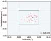
We analyzed and compared the anteversion and inclination after primary THA between 100 conventional non-navigated primary THAs and 100 imageless navigation primary THAs. Postoperatively, the inclination and anteversion of the cup was evaluated using standard anteroposterior and lateral radiograph views. A cup inclination of 40° ± 10° and anteversion of 20° ± 10° were regarded as the ‘Safe Zone’. There were 10 outliers of safe zone related to acetabular component position in the group of conventional non-navigated THA. However there were no outliers in the THA group of imageless navigation (Fig. 2).
We analyzed the cup position of cementless THAs using imageless navigation system in 100 consecutive hips. They were divided into two groups; Group I (n=71) consists of patients with body mass index (BMI)<25 kg/m2, and Group II (n=29) consists of patients with BMI>25 kg/m2. There was no statistically significant difference in anteversion (P=0.78) and inclination (P=0.47) between the two groups. This result was considered to be attributable to a small number of patients with a BMI of greater than 30 kg/m2 in our study and a low prevalence of obesity among Koreans compared to Western populations.
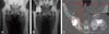
We also retrospectively analyzed the data for implant positions and clinical results in 40 patients (24 men and 16 women), who underwent a cementless revision THA using an imageless navigation with the concept of CA of Widmer1929). Postoperatively, the inclination of the cup was evaluated using standard anteroposterior radiographic views, and the anteversion of the cup and femoral stem was evaluated using CT scan. A cup inclination of 40° ± 10° and CA of the cup and femoral stem of 37° ± 10° based on Widmer's equation were regarded as the ‘Safe Zone’. The average anteversion of the revised femoral stems was 15.3° ± 2.9° (range, 9.5°-21.5°), whereas that of the remained femoral stems was 17.4° ± 9.7° (range, 4.2°-29.8°). The inclination, anteversion of the cup, and CA after revision THA were 42.3° ± 3.1° (range, 32.1°-48.2°), 25.0° ± 2.9° (range, 16.9°-29.5°), and 36.1° ± 3.4° (range, 27.2°-42.9°), respectively (Fig. 3). Therefore, the position of the implants, relative to the ‘Safe Zone’, showed no outliers after the revision surgery (Fig. 4). Neither dislocation nor osteolysis was observed after the surgery.
2) CT-based navigation
CT-based navigation was first introduced in THA by DiGioia et al.2) and Jaramaz et al.36), and nowadays has become the gold standard for surgical navigation THA. This system can offer position and alignment planning of the implant in sagittal, coronal and axial planes using CT images, and provide 3D reconstructed images of the bone and implant.
Based on the preoperative CT images, CT-based navigation processes 3D geometrical planning by reconstructing the surface of the bone using preoperative planning program and implant data. This CT based information is used for ROM simulation and registration intraoperatively. During the surgical procedure, a fixed tracker is attached to the pelvis and femur and the shape of the femur and pelvis is registered. The acetabular cup is placed in a planned orientation after acetabular reaming with the guidance of the navigation system. After resecting the femoral neck at the appropriate level, the femoral canal is broached as guided by the navigation, a technique that also helps in orienting the final placement of the femoral component. Once the joint is reduced, the hip is examined for ROM and impingement with the help of navigation system.
DiGioia et al.2) have suggested that when considering a cup inclination of 45° and anteversion of 20° as the safe zone, incidence of outliers of the safe zone for cup position was 78% using free hand technique, while position of acetabular cup were within the safety zone of 5° using CT-based navigation. In vitro study, Jolles et al.37) have reported that the accuracy of cup positioning was higher using CT-based navigation than using traditional methods of cup positioning. The usefulness of CT-based navigation has been reported by Sugano et al.38) in their study involving patients undergoing THAs with ceramic-on-ceramic bearings and Haaker et al.39) who performed cup placement using the navigation system in primary and secondary dysplastic hips.
Some disadvantages of CT-based navigation are additional patient irradiation for CT images, increased cost, and time requirements.
3) Fluoroscopy-based navigation
Fluoroscopy-based navigation was introduced to overcome a disadvantage of the time-consuming procedure of obtaining CT images in CT-based navigation. Both navigation systems have almost no difference in accuracy. However, Tannast et al.40) have stated that fluoroscopy-based navigation demonstrated no improvement in anteversion compared to conventional methods, due to error of registration of the mid-pubic point with fluoroscopy. Recent studies have recommended that fluoroscopy combined with pointer-based percutaneous palpation can increase accuracy of cup placement.
□ Meta-analysis Study for Navigated THA
To the best of our knowledge, 4 meta-analyses for computer navigation THA have been reported41424344), and all of these studies have suggested that navigated THA is more useful in achieving accurate cup placement than conventional THAs. Gandhi et al.41) reviewed 250 patients from 3 randomized controlled studies and reported that the incidence of outliers from the desired alignment of the acetabular component was significantly lower in patients who underwent computer navigation THA than those with freehand technique THA. Moskal and Capps42) did not find a statistically significant difference in acetabular component placement in navigated and conventional THA. However, in the analysis of results of 1,479 THAs from 9 studies, they observed that the acetabular components implanted with navigation are more often within the predetermined safe zone and hence the dislocations are less likely to occur as compared to the patients in conventional THA group. Xu et al.43) reviewed 1,071 hips from 13 randomized controlled studies and stated that the use of computer navigation in patients undergoing THA improved the precision of acetabular cup placement and reduced leg length discrepancy. In the analysis of 485 hips from 7 randomized controlled studies, Liu et al.44) reported that no statistically significant difference was found in mean angles of cup anteversion and inclination and deviation from the desired position of inclination between the conventional THA group and the imageless computer navigated THA group. However, they found a clear advantage of imageless navigation system in optimizing acetabular alignment, improved prostheses accuracy and reduced acetabular component outliers as compared to the conventional THA group.
2. Surgical Robot System
Although navigation system can offer 3D position of the surgical field, surgical-tool and implant, the operator may not place tools and implants on the surgical plane accurately. Moreover, conventional methods have the risk of intraoperative femur fractures, forecasting errors in implant size, leg length discrepancy and the risk of pulmonary embolism. To overcome complications derived from conventional methods, surgical robot system was developed.
Robotic system is classified into active and semi-active systems. Active system performs partial or complete milling procedures as programmed preoperatively. In semi-active system, the robotic arm is moved by the operator's hand by holding surgical tools and does not move outside of a milling path boundary.
1) Active robot system
Active surgical robots include CASPAR® (Orto Maquet, Rastatt, Germany) and ROBODOC® (Curexo Technology Corporation, Fremont, CA, USA); the ROBODOC System has been more widely used. ROBODOC® has been manufactured as TSolution One® (Think Surgical Inc., Fremont, CA, USA), a product with a new brand name since 2014. In the 1980s, this surgical robot for THA was first developed by veterinarian Howard Paul and orthopedic surgeon William Bargar with a collaboration of partners including IBM Co. and University of California, Davis. Since successful animal surgery using surgical robotics in 1989, Integrated Surgical Systems (ISS) was co-founded in 1990 to develop surgical robotic technology and commercialize ROBODOC® and ORTHODOC® to directly assist the surgeon during surgical procedures using computer programs. Since the first clinical use in Germany in 1994, several countries have started to use these surgical robots and reported clinical results. The US Food and Drug Administration (FDA) approved the ROBODOC® in 2008.
The registration methods of robot surgery are mainly divided into pin-based and pin-less methods. Initially, in a pin-base method, pins serving a fiducial marker are inserted into the greater trochanter and femoral condyles prior to the CT scan as an additional minor procedure before THA. Then the preoperative planning is registered by locating the pins and the CT Image data, based on which THA is performed within 24 hours. The robot recognizes the position of the patient's bone using implanted fiducial pins and performs milling according to the preoperative plan. On the other hand, in a pin-less method of registration, preoperative planning is done using CT images taken preoperatively. The milling plan is based on a virtual bone model and is applied to a real patient's bone by coordinating the virtual bone model and patient's bone recognized by the robot using the DigiMatch™ technique. Even though the pin-based method does not require the DigiMatch™ stage, the disadvantage is that it requires two operations. It is now rarely used due to problems arising from the use of pins. However, this registration method can be applied in patient with a fracture of the femoral head or in those having metal materials
The TSolution One® System consists of TPLAN® for a preoperative planning workstation and TCATTM (Think Surgical Inc.) for performing precise milling and reaming as planned preoperatively. TCAT™ is composed of TCAT™ arm for the control of actual movement and cutting tool connected at the tip of TCAT™ arm by coupler, and digitizer, monitor and bone motion monitor (BMM). A digitizer is used to collect points and locate the exact position of the patient's anatomy for precise surgical implementation. BMM senses patient's intraoperative motions in real-time. If bone motion occurs during surgical procedure, a bone motion monitoring system halts the system.
□ Clinical Results of Robot-Assisted THA
The first clinical study using ROBODC® in THA was an FDA-authorized multicenter randomized control study conducted in 136 hip replacements in the United States between 1994 and 1995. Although no difference was found in clinical results, radiographic findings revealed more precise alignment and fixation of the femoral stem. Three cases of intraoperative femoral fracture occurred in the control group and none in the ROBODOC® group45). In 1994, the German study reported that the surgical time decreased to 90 minutes and no intraoperative femoral fractures occurred with the use of ROBODOC® in 900 hip replacements (858 unilateral hip replacements and 42 bilateral hip replacements, including 30 revision cases)45). The ROBODOC® system has been suggested to be useful for cement removal for revision THA46). In 2003, Honl et al.47) achieved good results in limb length equality and stem orientation in THA using an active robot system, but they raised concerns over robot-assisted THA because the rate for switching to manual implantation during surgery was 18% and poor results were obtained in the robot-assisted group (dislocation rate of 18% and subsequent revision rate of 15%). Furthermore, Hananouchi et al.48) investigated the effect of the ROBODOC® surgery on periprosthetic bone remodeling and assessed dual energy X-ray absorptiometry (DEXA) and plain radiographs of 29 patients (31 hips) after ROBODOC® THA and 24 patients (27 hips) after manual THA. They observed a significantly smaller decrease of the bone mineral density ratio in the distal zones (zone 4 and 5) and more pronounced endosteal spot welds in the proximal medial portion in the ROBODOC® group (48% vs. 11% in the conventional group). In a study of the two-pin registration method through a posterior approach, Hagio et al.49) obtained better clinical scores and better stem alignment on radiographic evaluation at two years in the ROBODOC® group than in the control group. Nakamura et al.50) reported that ROBODOC® procedures also showed less variance in limb length inequality. Lim et al.51) asserted that robot-assisted short stem THA could increase the accuracy of stem alignment, improve leg length equality, and help reduce the risk of intraoperative femoral fracture as compared with manual rasping. Although there were concerns over the risk of developing osteonecrosis due to heat generation from milling of bones52), it was not clinically manifested. In addition, a transesophageal cardioechogram study demonstrated fewer incidences of pulmonary embolism in robotic milling of the femur than in manual rasping53), and a DEXA study showed less stress shielding phenomenon in the femur48). As the above findings demonstrate, robot-assisted THA has clearly improved the surgical precision of the procedure, but further studies are required, specifically those that include longer-term clinical results. In particular, there may be concerns about irradiation caused by CT imaging, soft tissue injury, and cost. Moreover, unlike in manual THA, operating time is extended by securing the patient in the fixator of the robot and also due to registration and verification procedures for coordination of 3D bone images and real bones. Therefore, the robotic surgery needs to be improved for conducting the surgical procedures through smaller incisions and shorter operating time.
2) Semi-active robot system
In semi-active system, the robotic arm follows the operator's hand by holding surgical tools and does not move outside of a milling path boundary. This robot system includes Acrobot® System (Acrobot Company Ltd., London, UK), MAKOplasty® System (Stryker, Orlando, FL, USA) and others. In the Acrobot® System, the operator manually controls the system using the drill bit at the tip of the robotic arm within a milling path boundary defined according to 3D-image-based preoperative planning. Previous study about this semi-active system54) was only for the hip resurfacing surgery. MAKOplasty® System is a semi-active boundary constrained robotic milling system that uses the RIO (Robotic Arm Interactive Orthopaedic) system and has been successfully used in precise reaming and cup placement55). MAKOplasty® was first introduced in 2004 and has begun to be applied to uni-compartmental knee arthroplasty since 2006. This system has been used in acetabular cup implantation after obtaining FDA approval for THA in 2010.
The procedure of MAKOplasty® THA including the express femoral work flow consists of three phases of planning, preparation and placement. In the planning stage, patient-specific 3D templates are formed using preoperative CT data to determine the optimal position for the cup and stem. Acetabular reaming and femoral neck resection and cavity preparation are performed for implant placement under robot guidance in the preparation stage, and implant placement is performed under stereotactic guidance and control of the robot system in the placement stage. The recent development of the enhanced femoral workflow which determines and measures stem position has enabled the application of concept of CA.
In a cadaveric study by Nawabi et al.56), MAKOplasty®-assistance showed more accurate cup positioning than manual implantation. Domb et al.57) asserted that use of the MAKOplasty® System allowed for improvement in placement of the cup within the safe zone, an important parameter that plays a significant role in long-term success of THA. Furthermore, they reported that 100% of robotic cups were placed within the Lewinnek ‘Safe Zone’ for anteversion and inclination compared to 80% of manual cases and 92% of robotic cups were placed within the Callanan ‘Safe Zone’ for anteversion and inclination compared to 62% of manual cases. Redmond et al.58) reported that learning curve of robotic THA did not result in additional clinical or technical complications.
The advantages of MAKOplasty® are that it provides accurate absolute cup position, assistance on cup placement and feedback. The disadvantages are additional patient irradiation for obtaining CT image and expensive equipment cost. Nevertheless, surgeons appear to adapt easier and more quickly to the semi-active robot system than active robot system. However, more evidence is needed to verify compatibility, safety and effectiveness8).
3. Patient Specific Template (PST) and Mechanical Navigation System
Navigation and robotics help to improve the accuracy of component positioning in THA, but broad clinical applications of these systems is hampered by high cost, additional time during intervention, problems of intraoperative man-machine interactions, and the spatially constrained arrangements of additional equipment within the operating room.
In this respect, PST has been developed as an alternative method of CAOS for more precise surgery without requiring an expensive hardware installation59). PST uses preoperative 3D images and has been applied to acetabular cup placement guide in THA and femoral guide wire insertion for hip resurfacing6061626364). However, it requires preoperative CT evaluation, a higher expense of producing the template and skill for optimal and precise preoperative planning. Moreover, PST requires a wider exposure through a larger skin incision than navigation assisted surgery.
HipSextant™ (Surgical Planning Associates Inc., Medford, MA, USA) is a patient-specific computer-assisted mechanical navigation system which is designed to guide acetabular cup placement. The instrument is adjusted for each patient based on patient-specific 3D models based on APP and a 3 point sextant plane obtained from CT imaging using a preoperative planning software application65).
ROLE OF CAOS IN COMPLEX THA
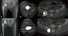
An important role of CAOS in THA is assisting more accurate surgery in difficult and complex cases. For example, precise implant placement is a challenging procedure in osteopetrosis patients with hard brittle bone and obliterated meduallry canal. The authors were able to place the acetabular cup and femoral stem in a relatively accurate position using imageless navigation for THA in a 26-year-old woman with degenerative osteoarthritis caused by osteopetrosis. The anteversion of the femoral stems and acetabular cup in this patient were 10° and 28°, respectively. The CA by equation of Widmer was 35° (Fig. 5). Egawa et al.66) have reported a favorable result of THA in osteopetrosis using computer-assisted fluoroscopic navigation. Since the femoral canal is obliterated, the use of active robot system can be more effective in accurate positioning of the femoral stem.
Furthermore, the active robot system appears to be effective in severe dysplastic hips with shallow acetabulum and narrow femoral canal. More recently, the newly developed semi-active robot system can perform more precise surgery with the robot arm fitted for controlled reaming based on the preoperative evaluation and planning of the bone defect using 3D CT images. Accurate positioning of implants may be difficult in obese patients. Gupta et al.67) reported that robotic-assisted computer navigation provided accurate and reproducible placement of the acetabular cup within safe zones for inclination and version in obese patients.
CT-based navigation or robot system requiring preoperative CT imaging may be less useful in revision THA due to metal artifacts, whereas imageless navigation can be helpful for guiding revision THA29).
RECENT EVOLUTION IN CAOS FOR THA
When using imageless navigation, even though accurate registration of the APP is acquired as the reference plane for acetabular cup position, neither the pelvic tilt nor the FPP is not taken into consideration. To overcome this limitation, Davis et al.34) reported a new method of registration in navigated hip arthroplasty without the need to register the APP (Fig. 6). In this study, the mean error in component position was −1.1° (standard deviation [SD], 3.1°) for inclination and 0.9° (SD, 4.3°) for anteversion.
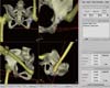
Researches regarding pelvic tilt and FPP by Miki et al.68) and Suzuki et al.11) showed the efficacy of the FPP using CT-based navigation in THA. Nishihara et al.9) reported that the individual sagittal angle of APP is not always flat in a neutral (zero) position of the hip and it can be affected by an individual's shape, aging, or spinal deformity due to osteoporosis. Then he recommended, as a pelvic plane reference, the FPP in supine which adjusts APP sagittal tilt for targeting the cup orientation using CT-based navigation (Fig. 7).
The early active robot systems for THA had a high incidence of complications, and the high complication rate was caused by low reproducibility related to pin based registration, a wide exposure by the use of a bulky proximal bone fixator clamp, and the occurrence of more muscle damage. Since then, ROBODOC® has been modified to resolve these problems by using the DigiMatch™ technique in registration and reducing the size of the proximal bone fixator clamp.
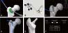
In the past, the active robot system was available only for femoral stem positioning. But recently the system has advanced and can be applied to reaming and positioning of the acetabular cup as well (Fig. 8). Technically, acetabular reaming is performed by placing the TCAT™ arm within the preoperatively planned inclination and anteversion orientation of the cup. However, the operator needs to directly adjust the depth of reaming because the function of acetabular cup placement is to provide position information and reaming direction. In addition, the robot arm is currently designed with a rotation axis added at the tip of 4-axis Selective Compliance Articulated Robot Arm (SCARA) and modification is in progress to provide the robot arm with broad range of motions, allowing for added flexibility and to integrate and operate the software of the control cabinet.
On the other hand, in the past, the semi-active robot system was available only for positioning and placement of the acetabular cup. Recently however, this system has become available in guiding femoral stem insertion as well with the development of the enhanced femoral workflow (Fig. 9). Thus, the recent development of the enhanced femoral workflow which determines and measures femoral stem position has enabled the application of concept of CA.
CONCLUSION
Though there have been substantial advancements in computer-assisted THA, its use can still be controversial at present due to the steep learning curve, intraoperative technical issues, high cost and etc. However, looking back over the history of remarkable advance in computers, the future development of CAOS will go beyond our imagination. CAOS, in the future, will certainly enable the surgeon to operate more accurately and lead to improved outcomes in THA. We need to undertake a range of efforts for more advances in the field of computer-assisted THA.


 XML Download