

 PDF
PDF ePub
ePub Citation
 Print
Print


INTRODUCTION
Due to the three-dimensional (3D) configuration of the femur neck and the head, it is unavoidable to have 3D effects on the femoral head by the femur osteotomy just after one plane osteotomy such as a varus or derotation osteotomy. The distal femur osteotomy of the frontal and sagittal plane causes clinically insignificant 3D effect on the femoral head.
Most of orthopedic surgeons know about the varus change of the neck-shaft angle of the anteroposterior (AP) hip X-ray by the internal rotation of the lower extremity1), but do not consider seriously about the 3D effect of the proximal femur osteotomy. The 3D effects of the single plane osteotomies of the proximal femur were compared and analyzed by the trigonometric method.
MATERIALS AND METHODS
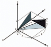
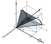
The shape of the right proximal femur was simplified as bent lines. The bent lines were the continuation of the three points; the center of the femoral head (H), the center of femoral neck at the base (N), and the center of the femoral shaft (S).
Then rotated the proximal femur at the junction of the neck and shaft with the each rotation axis of X, Y, Z, defined the frontal plane as a XY plane, sagittal plane as a YZ plane, and transverse plane as a XZ plane. The projected cervicofemoral angulation in the frontal plane was defined as 'α' that was AP neck-shaft angle, angleαis angle v plus 90, and angle v is valgus angle of femoral neck. In the sagittal plane 'β' was the flexion angle, in the transverse plane 'γ' the anteversion angle, the true neck shaft angle 'δ', and the angle between the femoral neck and the frontal plane 'φ' was the inclination angle (Fig. 1).
With just two angles of femoral neck among angles of three planes (v,β, andγ), the remaining one angle could be calculated by the following formulas.
tan v=B/A, tanβ=C/B, tanγ=C/A
tan v=tan γ/tan β, tan β=tan γ/tan v, tan γ=tan v · tan β
With these trigonometric formulas, the change of angle in each plane could be calculated (Table 1).
With the value of true head neck distance (R) and just two angles among three angle (v, β, and γ), could calculate the value of A, B, and C.
With two angles of femoral neck in three planes (v, β, γ) and true head-neck distance (R), could calculate three coordinates (A, B, C).
To avoid the confusion, the varus and valgus osteotomy was defined as the direction of movement of the distal femur after osteotomy in the frontal plane, the flexion and extension osteotomy in the sagittal plane and the external (derotation) and internal (rotation) rotation osteotomy in the transverse plane.
RESULTS
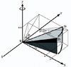
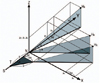
The varus osteotomy of the proximal femur in the frontal plane with the rotation axis 'Z' that meant the increase of the X coordinate and the decrease of Y coordinate with constant Z coordinate resulted in decreased anteversion in the transverse plane and increased flexion in the sagittal plane (Fig. 2).
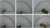
A real bone model with 2 K-wires representing x and y axis at the neck shaft junction, and 1 K-wire inserted along the center of the femur neck showed frontal neck-shaft angle of 128°(valgus angle 38°), sagittal neck-shaft angle of 15°, and transverse neck-shaft angle of 14° (Fig. 3A-C). With 20°varus rotation in the frontal plane, showed the change of the frontal neck-shaft angle to 108°(valgus angle 18°), sagittal neck-shaft angle to 17°, and transverse neck-shaft angle of 10° (Fig. 3D-F).
If two angles were changed to any correction, the other one angle is definitely confined.
If varus (20°) correction was just carried out to the proximal femur with its angle of valgus 45°, flexion 25° and anteversion 25°, final angles of the neck in each plane was valgus 25°, flexion 40°and anteversion 20°. Using the Table 1, when we were planning the varus osteotomy (v was decreasing), also got flexion (βwas increasing) and derotation (γ was decreasing) effect. When valgus angle was less than 45°, varus osteotomy could cause the more flexion effect than derotation effect, because the decrement of Y axis was bigger than the increment of X axis. Reversely when valgus angle was more than 45°, varus osteotomy could cause the more derotation effect than flexion effect.
Like the same manner, the valgus osteotomy of the proximal femur caused increased anteversion and decreased flexion.
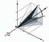
The derotation osteotomy of the proximal femur in the transverse plane with the rotation axis 'Y' that was performed by external rotation of the distal femur after osteotomy resulted in varus in the frontal plane and extension in the sagittal plane (Fig. 4).
On the contrary, the rotation osteotomy of the proximal femur caused valgus and flexion.
The flexion osteotomy of the proximal femur in the sagittal plane with the rotation axis 'X' resulted in increased anteversion in the transverse plane and varus in the frontal plane (Fig. 5).
Reversely the extension osteotomy of the proximal femur caused valgus and decreased anteversion. The effects of the every single plane osteotomy were simplified in the diagram (Table 2).
For example, varus single plane osteotomy resulted in increased X coordinate, decreased Y coordinate and constant Z coordinate (ΔX↑, ΔY↓, ΔZ→). This osteotomy makes not only decreased Y to X coordinate ratio (y0/x0>y1/x1: varus) but also increased Z to Y (z0/y0<z1/y1: flexion) and increased Z to X coordinate ratio (z0/x0>z1/x1: derotation).
In clinical practice, the site of the proximal femoral osteotomy could be distal to the neck-shaft junction, different 3D effects of this subtrochanteric osteotomy comparing to the head and neck junction osteotomy were inevitable except rotation or derotation osteotomy.
The subtrochanteric varus osteotomy could induce increase of ΔX and ΔY coordinates comparing to the varus osteotomy at the neck shaft junction with the same degrees correction (Fig. 6).
The change of Y coordinate after subtrochanteric varus osteotomy was more decreased than that of neckshaft junction varus osteotomy; ΔY=D (1-Cos α). The change of X coordinate after subtrochanteric varus osteotomy was more increased than that of neck-shaft junction varus osteotomy; Δx=D sin α.
DISCUSSION
There are many examples of 3D effects of the proximal femur by one plane movements, such as the internal rotation of femur causes the varus change of the proximal femur. For measuring a femoral anteversion, Kane et al.2) used a single roentgenographic measurement of femoral anteversion by projecting the femur longitudinally from the knee to hip with 10°to 20°abduction of the thighs and reported +1°to -6°differences from the real anteversion. These results are expected by the 3D effect of the abduction of the thighs that causes varus of the femur head, so the decreased anteversion of the femur is resulted from abduction of thighs.
Howell et al.3) calculated the angle of anteversion and varus of proximal femur in Perthes' disease by a method using single AP radiograph. They suggested that the ratio of major and minor axis of ellipse created by epiphyseal plate of femoral head on AP radiograph depends on anteversion and true neck-shaft angle.
Nelitz et al.4) stated that proximal derotation osteotomy resulted in increased varus angulation of the hip and distal derotation osteotomy resulted in increased valgus angulation of the knee due to antecurvatum of femoral shaft.
With the valgus in the AP X-ray and increased anteversion in computed tomography scan, some cases show a decreased flexion in the lateral X-ray and a normal range of AP neck-frontal plane angle, that means a normal Z coordinate, decreased X coordinate, and increased Y coordinate. The varus osteotomy with rotation axis Z is enough and no need to correct the anteversion because the increased anteversion is a pure reflection of the valgus.
With the valgus and anteversion, some cases show an increased Y coordinate, a decreased X coordinate and an increased Z coordinate. The derotation osteotomy can change the valgus also; there is no need to add the varus osteotomy to the derotation osteotomy. Some cases show an increased Y and Z coordinate with a marked decreased X coordinate. Both valgus and derotation osteotomies are necessary because the varus osteotomy or the derotation osteotomy only is not enough to correct the deformity in these cases. The normal values of the three coordinates of the proximal femur will be needed to plan any kind of corrective osteotomy in case of complex deformity.
Liu et al.5) reported that the angle of neck-frontal plane (angle 'φ') or inclination could be calculated using the true or apparent neck-shaft angle and angle of version. And they stated that varus osteotomy decreased anteversion and valgus osteotomy increased anteversion due to the relationship with version and neck-shaft angle.
Some papers suggested different measurements methods of femoral anteversion by biplane radiography67891011). With these two angulations, true femoral neck-shaft angulation and angle of anteversion could be calculated like Table 1.
The subtrochanteric varus osteotomy could induce more vertical shortening and increased medial offset than the neck-shaft junction varus osteotomy. The subtrochanteric valgus osteotomy could induce less vertical lengthening and decreased medial offset than the neck-shaft junction valgus osteotomy. The subtrochanteric flexion osteotomy could induce more vertical shortening and increased anteversion than the neck-shaft junction varus osteotomy.
The subtrochanteric extension osteotomy could induce less vertical lengthening and more decreased anteversion than the neck-shaft junction varus osteotomy. But the rotation or derotation osteotomy in the subtrochanteric site has no 3D difference with the neck-shaft junction osteotomy due to the same rotation axis.
Single plane osteotomy had single rotation axis X, Y or Z. After single plane osteotomy, one coordinate which was on the rotation axis was not changed, but the rest two coordinates which were not on the rotation axis were changed. Of the rest two coordinates, one was increased and the other was decreased. This increase and decrease of the two coordinates in single plane osteotomy could change the location of the femoral head and the angle of femoral neck in all three planes (XY, YZ, and XZ plane). Single plane osteotomy could control just two coordinates, while double or triple osteotomy controlled all three coordinates. Thus, single plane osteotomy had the effect of correction in three planes (3D effect), but it was limited owing to the fixed one coordinate.
Clinical relevance of this study is that a combined deformity correction osteotomy is simplified by the single plane osteotomy in case of the synchronous deformity. For example, if there is valgus and increased anteversion deformity of the femoral head, we might correct the whole deformity by just varus osteotomy or derotation osteotomy alone. But if there is varus and increased anteversion deformity of the femoral head, we have to do combined valgus and derotation osteotomy to correct the deformity.
Using Table 1, we can expect the remaining plane neckshaft angle after changing the 2 plane neck-shaft angles by corrective osteotomy of the proximal femur. For example, if we make AP neck-shaft angle and anteversion angle to 135°and 15°each by the osteotomy, then we find that lateral neck-shaft angle is fixed to 15°


 XML Download