

 PDF
PDF ePub
ePub Citation
 Print
Print


INTRODUCTION
Plain radiographic examination is the most basic and critical method for the diagnosis of hip disorders. An appropriate image examination and understanding of standard radiographic techniques can help to achieve better diagnostic accuracy. In the present review, we discuss plain radiographic techniques, image features, and proper interpretation of images.
STANDARD RADIOGRAPHIC TECHNIQUES
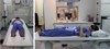
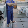
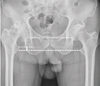
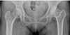
In plain radiography (X-ray), anteroposterior and lateral hip radiographs are usually taken. An anteroposterior hip radiograph includes images of both sides of the hip on the same film and projects towards the middle of the line connecting the upper symphysis pubis and anterior-superior iliac spine; the distance between the X-ray tube and the film should be 1.2 m. If anteroposterior hip radiographs are taken in a supine position, one of the most common mistakes is image distortion as the hip is externally rotated1). Thus, either both patellae should be facing forward or lower extremities should be internally rotated by 15°-20° to accommodate femoral anteversion in anteroposterior hip radiographs (Fig. 1). Flexion contracture may increase or decrease image magnification. In such cases, accurate anteroposterior images may not be achievable, and the patient should be removed from the table and then both legs should be positioned perpendicularly in a flexion position for radiography.
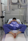
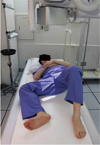
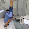
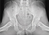
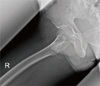
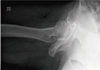
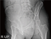
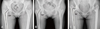
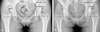
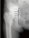
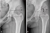
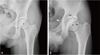
There are multiple imaging techniques for lateral hip radiography, including the frog-leg lateral view, Löwenstein view, and cross-table lateral view. In the frog-leg lateral view, both sides are shown on one image and the knee joint is flexed 30°-40° in a supine position, while the hip is externally rotated by 45° so that the image is taken toward the middle of the line connecting the upper symphysis pubis and the anterior-superior iliac spine (Fig. 2). In the Löwenstein view, patient is turned onto the affected hip at least 45° with the hip flexion angle of 90° and internal rotation angle of 45° in a supine position and then images of each side are taken vertically from the groin region (Fig. 3). In the cross-table lateral view, a lower extremity is internally rotated by 15°-20° in a supine position and then the hip and knee joints on the other side are flexed to prevent interference in radiographic projection; a cassette is positioned on the side of the hip at the right angle relative to the incidence angle, thereby projecting toward the groin region at 35°-45° of incidence parallel to the longitudinal axis of the femur (Fig. 4). Lastly, the false-profile view of the hip is obtained with the pelvis rotated 65° relative to the bucky wall stand, with the foot on the affected side parallel to the radiographic cassette (Fig. 5).
EVALUATION OF IMAGES
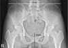
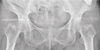
In order to evaluate an image, it is critical to confirm that it was properly taken and the patient was in an appropriate position. In particular, the tilt and rotation of the pelvis should be known precisely during evaluation of an anteroposterior hip radiograph. In a standard anteroposterior hip radiograph, the coccyx and symphysis pubis should be in a straight line and positioned in the middle line of the image, both sides of the iliac wings and obturator foramina should be symmetric, while the distance between the superior border of the pubic symphysis and the tip of the coccyx should be between 1 and 3 cm2) (Fig. 6). In addition, the greater and lesser trochanters should be clearly distinguishable, while the greater trochanter may not significantly overlap with the femoral neck; the calcar femoris needs to be clearly visible and there should be very little elliptical overlap between the anterior and posterior margins of the head-neck junction. The likelihood of inappropriate correction of femoral anteversion was reported to be lower if the thickness of the lesser trochanter is less than 5 mm3). As mentioned above, the most common error in taking an anteroposterior hip radiograph is that the hip is externally rotated while the image is being taken; in this case, the greater trochanter overlaps with the femoral head and the posterior head-neck junction is projected to the superior to the anterior head-neck junction, thereby distorting the image. These errors may negatively affect fracture diagnosis. For instance, they may make it difficult to diagnose a valgus-impacted fracture of the femoral neck and lead to a misdiagnosis of an osteophyte as a stress fracture. Lastly, accurate preoperative templating may not be achieved and measurement errors could be resulted when performing studies dealing with radiographic assessments1).
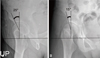
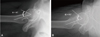
Various lateral hip radiographs have specific advantages and limitations. For example, the frog-leg lateral view can be taken multiple times in a similar position and makes is easy to evaluate the sphericity of the femoral head, joint congruency, and the shape and offset of the head-neck junction (Fig. 7). Similarly, in the Löwenstein view, it is easy to take radiographs of each side (Fig. 8). One should note however that both these views may have disadvantages as the head-neck junction is often not clearly visible because it is obscured by the greater trochanter; therefore, these two views are rarely used to diagnose fractures. In the cross-table lateral view, the greater trochanter is positioned posteriorly so that the femoral head-neck junction is well defined, but bony landmarks may not be clear in obese patients (Fig. 9). In the false-profile view, the anterior coverage of the femoral head can be assessed (Fig. 10).
Every radiograph provides important information critical for accurate diagnosis of hip disorders4). Generally, anteroposterior and false-profile views provide information on the shape of the acetabulum, whereas other lateral images provide information on proximal femoral parts, including the femoral head. The following specific information can be obtained from anteroposterior hip radiographs: 1) leg length, 2) neck-shaft angle, 3) acetabular coverage: the lateral center-edge (CE) angle and femoral head extrusion index, 4) acetabular depth, 5) acetabular inclination, 6) acetabular version, 7) head sphericity, and 8) joint space width.
1) Leg length: Leg length differences can be assessed by comparing with the height of the iliac crests on both sides. It can also be assessed by measuring the difference in distance between the most prominent part of the lesser trochanter and a parallel line connecting either the teardrop or ischial tuberosity (Fig. 11).
2) Neck-shaft angle: This is the angle formed by the longitudinal axis of the femoral shaft and the line drawn along the axis of the femoral neck, which passes through the center the femoral head. The normal range of the neck-shaft angle is between 125° and 140°. If the angle is either larger or smaller than this range, it is defined as coxa valga or coxa vara, respectively (Fig. 12).
3) Acetabular coverage: There are two methods to measure the degree of acetabular coverage, the lateral CE angle and femoral head extrusion index5) (Fig. 13). The lateral CE angle is defined as the angle between the vertical line from the center of the femoral head and the line connecting the lateral margin of the acetabulum; the normal range of this angle is between 25° and 40° and acetabular dysplasia is diagnosed if it is less than 20°. If it is more than 40°, acetabular coverage might be considered as excessive. The femoral head extrusion index indicates the percentage of the femoral head not covered by the acetabulum and is considered normal if it is less than 25%.
4) Acetabular depth: The positions of the acetabular fossa and femoral head are judged on the basis of the ilioischial line. If the acetabular fossa meets the ilioischial line, it is diagnosed as coxa profunda, whereas protrusio acetabuli is diagnosed if the femoral head is medially displaced and overlaps with the ilioischial line (Fig. 14).
5) Acetabular inclination: Although it should be termed as the acetabular roof angle of Tönnis, it is often abbreviated as the Tönnis angle5). The first line is drawn through the inferior aspect of the sclerotic acetabular sourcil parallel to the inter-teardrop line. The second line connects the inferior and lateral aspects of the sclerotic acetabular sourcil. The angle created by the intersection of these two lines is the Tönnis angle (Fig. 15). The Tönnis angle between 0° and 10° is considered normal. If it exceeds 10°, the likelihood of hip instability might be increased, whereas if it is less than 0°, pincer-type femoroacetabular impingement can easily occur.
6) Acetabular version: Depending on the presence of a crossover or figure-of-eight sign, all acetabula are classified as either anteverted or retroverted, respectively6). Anteversion is defined as the absence of an intersection between the line connecting the anterior margin of the acetabulum and a line connecting its posterior margin, whereas retroversion is defined as the presence of such intersection. A deficient posterior wall (the center of the femoral head is positioned lateral to the posterior margin of the acetabulum) and a prominent projection of the ischial spine into the pelvic cavity are additional signs of acetabular retroversion7) (Fig. 16). In particular, one should be careful when evaluating acetabular version because it can vary considerably in terms of tilt and rotation. Increased pelvic tilt or rotation to the ipsilateral hip leads to a more pronounced retroversion sign and vice versa2).
7) Head sphericity: The head shape can be classified into either spherical or aspherical; if the epiphysis of the femoral head deviates more than 2 mm from the reference circle, it is classified as aspherical (Fig. 17).
8) Joint space width: Joint space width is measured using standing anteroposterior hip radiographs; it is defined as the minimum interbone distance between the highest margin of the femoral head and lowest margin of the acetabulum. Joint space width is often used for the Tönnis classification of ostarthritis (Fig. 18).
In the false-profile view, the anterior CE angle of the acetabulum can be assessed8). To measure it, the angle between the vertical line from the center of the femoral head and the posterior margin of the acetabulum is measured; if this angle is smaller than 20°, the anterior coverage of the acetabulum is considered as insufficient (Fig. 19).
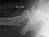
In lateral hip radiographs, the shape and offset of the femoral head-neck junction as well as the offset alpha angle are assessed9). The anterior femoral head-neck junction can be classified into three types in relation to the posterior head-neck junction on the basis of the gross appearance of the radius of curvature. It is considered as normal if the anterior and posterior concavities are grossly symmetric. If the anterior one is less concave than the posterior, it is considered to have a decreased head-neck offset, and if the anterior shape is convex, it is diagnosed as a cam deformity10). The quantitative methods used to measure femoral head-neck junction morphology include the head-neck offset ratio and the alpha angle4). The head-neck offset ratio can be assessed using three lines: (1) a horizontal line between the center of the long axis of the femoral neck and the center of the femoral head; (2) a line parallel to line 1 through the anteriormost aspect of the femoral neck; and (3) a line parallel to line 1 through the anteriormost aspect of the femoral head. The head-neck offset ratio is calculated by dividing the distance between lines 2 and 3 by the diameter of the femoral head (Fig. 20). If the ratio is less than 0.15, a cam deformity is likely present. Although the alpha angle can be measured more accurately using an axial computed tomography or magnetic resonance imaging, it can also be assessed with the use of lateral radiographs by measuring the angle between a line connecting the center of the long axis of the femoral neck and the center of the femoral head, and a line from the center of the femoral head to the point on the anterolateral head-neck junction where the radius of the femoral head begins to increase beyond the radius found more centrally in the acetabulum, where the head is more spherical (Fig. 21). A cam deformity is diagnosed if the alpha angle exceeds 50°-55°
 XML Download