

 PDF
PDF ePub
ePub Citation
 Print
Print


INTRODUCTION
We orthodontists should treat an orthodontic patient without extracting teeth depending on the circumstances of a case or the patient's demand. To treat maxillary arch without extraction of premolars, distalization of the maxillary molars is required and extraction of upper third molars is needed. For this case several kinds of orthodontic appliances, e.g., headgear, pendulum, and other appliances have been used for molar distalization.123 Headgear is the most commonly used extra-oral orthodontic appliance, but headgear is not quite aesthetic and requires patient's compliance. Hence, intra-oral appliances are commonly used for these purposes more effectively.4
Mini-screws and mini-plates are widely used for distalization of posterior teeth because of the recent developments of skeletal anchorage systems. In the maxilla, more effective treatment alternative can be provided by applying skeletal anchorages in case of less effective treatments using traditional orthodontic appliances.56 Distalization of mandibular molars is more difficult than distalizing maxillary molars. The anatomical structure of the mandible such as the lingual cortex of it7 can be an obstacle for distalizing mandibular molars. Therefore, using a conventional removable appliance or a headgear in the mandible is clinically less effective and skeletal anchorages should be considered due to the anatomical nature of the mandible. For example, dento-alveolar and skeletal Class III malocclusion treatment cases were reported to have received an effective treatment through distalization of posterior teeth by inserting mini-screw or mini-plate in retromolar areas.89
Effective distalization of posterior teeth requires applying orthodontic forces to appropriate position of target teeth. Therefore, a type of finite element (FE) analysis is needed to figure out the proper position of applying orthodontic forces. FE analysis is widely used to analyze and forecast biomechanical characteristics of object movements. In orthodontics, a type of FE analysis can be used as a useful interpretation tool for an orthodontic force analysis. In particular, identifying biomechanical properties of dentition by using FE method will be helpful to provide more effective and less time consuming treatments to orthodontic patients.10 The aim of this study was to analyze the biomechanical characteristics of distalizing mandibular molars through a FE analysis according to changing the vertical positions of orthodontic forces using a modified L-type mini-plate.
MATERIALS AND METHODS
Construction of the finite element model
The individual tooth model of mandibular right side (Model B3-305; Nissin Dental Products Inc., Kyoto, Japan) was scanned to make teeth images. The mandibular arch model (Model 400; Hanil Dental Inc., Paju, Korea) was scanned to make the mandibular teeth alignment image. Scanned these images and the general mandibular skull image were used as the basis to reconstruct the mesh model of the mandibular right side for the FE analysis.
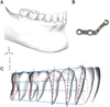
The visual reconstruction of bone and tooth images was performed with ADINA version 9.2 (ADINA R&D Inc., Watertown, MA, USA) to get a three-dimensional (3D) model (Figure 1A). This reconstructed model of teeth and bone was also modeled for the FE analysis and total 427,864 nodes and 1,892,370 solid elements (4-node tetra type) were used in this model. FE analysis was performed with ADINA version 9.2. The 3D FE model of alveolar bone was generated to fit the teeth and the periodontal ligament. The alveolar bone design was under the cemento-enamel junction relation.1112 The thickness of periodontal ligament was set as a 0.2 mm uniform layer.
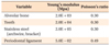
The design of the bracket followed MBT® brackets (3M Unitek, Monrovia, CA, USA). In the analysis model, constructed brackets were set from the mandibular canine to the mandibular second molar for the efficient teeth distalization. The mini-plate was designed on the basis of a modified L-type mini-plate (MCT, Yongin, Korea) (Figure 1B). The main archwire was modeled according to 0.016 × 0.022 inch stainless steel archwire and engaged only from the lower canine to second molar in right-sided mandible excluding lower anterior teeth. It was the reason that we tried to assume initial retraction of lower posterior teeth clinically without jiggling effect1314 of lower anterior teeth in non-extraction case. A 0.016 × 0.022 inch stainless steel archwire as a minimum rectangular archwire was needed to retract lower canine and posterior teeth in current study. There were no-play and a rigid-link relationship between brackets and the archwire because it is not necessary to slide the archwire within the brackets. The contact relationship of bracket slot and the archwire was the surface contact. And, all teeth used in this study had the surface contact relationships with each other as an independent object. All materials were considered to be homogenous, isotropic, and had linear elasticity. According to previous study, Table 1 shows materials' properties such as Young's modulus and Poisson's ratio.15
Distalization method
A modified L-type mini-plate was placed on the ramus area of the mandible. We assumed that the mini-plate and the mandible was a rigid-link relationship in FE model. Force was applied at the bracket level of mandibular canine and at the cemento-enamel junction level of the mandibular canine by bending the archwire vertically to make a lever-arm on the mesial side of the mandibular canine. The vertical position of a modified L type mini-plate's hook could be changed by bending of the mini-plate (Figure 2A and 2B). Figure 2C shows the horizontal force vector on occlusal view which is engaged from the center of the mandibular canine bracket slot to the distal end of the mandibular second molar bracket slot.
The 200g of the distalization force was applied at the mandibular canine. Force was applied at the bracket level of mandibular canine and at the cemento-enamel junction. The results of displacement were expressed in each X, Y, Z axis. X axis is the direction of transverse movement. Y axis is the direction of the anterior-posterior movement. Z axis is the vertical movement. The positive values of each X, Y, Z axis means right, anterior, upward movement.
Three points were selected at the position dividing the coronal, middle, and apical thirds of each tooth into four parts respectively. Hence, total 9 points were selected for each tooth displacement evaluation. The distal roots of the mandibular first and second molar were selected (Figure 1C).
RESULTS
Tooth movements according to force application at bracket level
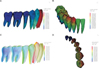
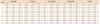
In the Y-axis, the displacement amount became greater at the coronal area of posterior teeth. Tipping movements were more prominent toward posterior teeth. In the X-axis, the crown parts of teeth showed the buccal movement in the mandibular arch. However, the movement pattern of the root areas showed the lingual movement in the mandibular arch. The intrusive movement increased toward posterior teeth of the mandible except the mandibular canine (Figure 3, Table 2).
Tooth movements according to force application at the cemento-enamel junction level
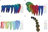
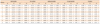
In the Y-axis, the displacement amounts at the apical area of each tooth were greater than the coronal area. The displacement amounts showed mostly similar in root areas (Table 3). Figure 4 showed almost bodily movements in all teeth except the mandibular canine. In the X-axis, all areas of teeth showed the buccal movement in the mandibular arch. In the vertical movement, the extrusive movement tendency became prominent toward the posterior teeth except the mandibular canine (Figure 4, Table 3).
Comparison of the mode of tooth movement according to vertical force application at the mandibular canine (Bracket level versus cemento-enamel junction level)
In the Y-axis, resultant displacement was larger in the root area when orthodontic force was applied at the cemento-enamel junction level compared to bracket level (Tables 2 and 3). Both force application produced tipping movement. However, more bodily displacement was produced at the cemento-enamel junction level than the bracket level. In the X-axis, all crown areas of teeth showed the outward movement of the mandibular arch. For the vertical movement, the unwanted extrusive movement was produced when applying the force at the cemento-enamel junction level compared to the bracket level (Figures 3 and 4). The displacement magnitude is the sum of all axes displacement and express total displacement of the movement in the 3D space. The rotation of teeth was less when force applying to the cemento-enamel junction level compared to the force application at the bracket level (Figures 3D and 4D).
DISCUSSION
For orthodontic treatment, a non-extraction approach should be considered, according to a patient's skeletal pattern and dental alignment. Mandibular molar distalization and uprighting can be applied clinically to correct slight crowding, or to facilitate prosthodontic treatment.
The clinical procedure to distalize mandibular teeth is highly complicated and therefore challenging. Conventional orthodontic appliances have historically tended to elicit tipping rather than bodily movement, before the advent of skeletal anchorage protocols such as orthodontic mini-screws and mini-plates. The degree to which tipping occurs is at least partially dependent upon the appliance type. And compliance should be considered when using intraoral removable appliances or extraoral appliances. Generally compliance was low in young patients.16
Various methods of skeletal anchorage have been developed, such as mini-screws and mini-plates, and have enjoyed longtime widespread usage. A case using mini-screws and modified palatal anchorage plates to treat an adolescent skeletal Class II patient with an anterior open bite was reported.17 In addition, other studies have demonstrated the usefulness of skeletal anchorage in improving bialveolar protrusion, or alternatively for protraction of maxillary teeth.1819 Movement patterns for mandibular versus maxillary teeth are different due to the anatomic nature of mandibular bone.7 Hence, mandibular molars distalization is more challenging than distalization of maxillary molars. Lower molar distalization can generally only occur in smaller increments as compared with maxillary molars. Therefore, it is vital to design and apply the proper vectors of orthodontic force in order to achieve effective treatment results.
In this FE analysis, orthodontic force for mandibular molar distalization was not applied beyond the mandibular canines. An important clinical consideration concerns unwanted anterior displacement that could occur if orthodontic distalization forces were to be extended into these areas. Hence, mandibular orthodontic brackets were bonded only from the second molar to the canine.
The mandibular FE model as described was based on a hemi-mandibular form (Figure 1A). Vertical and horizontal forces were applied in order to determine optimal points of application for mandibular molar distalization (Figure 2). Displacement of the lower posterior teeth within the computed FE model was measured at the coronal, middle, and apical thirds for each tooth (Figure 1C). In the Y-axis, the amounts of movement were assigned specific colors for improved visual interpretation. Therefore, if a tooth was assigned more than one color, the results implied a possible combination of resultant movement types (e.g., tipping, bodily movement, and varying magnitudes of movement). In this study, the higher the proportion of uniform color along a tooth axis, the more likely that the tooth would undergo bodily movement as opposed to tipping (Figures 3A and 4A). If each part of a given tooth (coronal, middle, and apical thirds) had been assigned the same color, the degree of displacement would tend to be consistent. However, if each tooth section had been assigned a different color, it indicated that, when measured at various points along the tooth's axis, the tooth would tend to manifest differing degrees of displacement.
In the Y-axis, the similarity of indexing color of target teeth was higher when the force was applied to the cemento-enamel junction level as compared with the bracket level (Figures 3A and 4A). These results showed that displacement within the mandibular molar region was likely to be bodily movement. Therefore, if the point of force application is moved vertically, from bracket level to the cemento-enamel junction level, then the application of orthodontic force can engender more bodily movement. Vertical position of force application is, therefore, an important consideration, since more efficient translatory movement was achieved by changing the vertical force position. It is thought that the as the cemento-enamel junction level of the mandibular canine was below that of posterior teeth, it would be in the vicinity of the center of resistance vertically in all posterior teeth of this study, even though we cannot digitize the exact position of the center of resistance in them. Jo et al.20 showed that the center of resistance of the 4 mandibular anterior teeth group, 6 mandibular anterior teeth group, and the complete mandibular dentition group. However, it is not appropriate to adopt their results to our study because the current study had a different condition. I.e., only five teeth of one-sided mandible were used to simulate distalization of lower teeth.
Sung et al.21 reported that displacement of the entire maxillary arch may be dictated by a direct relationship between the center of resistance of the whole arch and the line of action generated between the miniscrews and force application points at the archwire. In addition, Sohn22 also proved that lower second molar were tipped distally in all experimental group according to changing the hook length while retracting maxillary and mandibular dentition using a mini-screw. Their results were not consistent with our study in the pattern of root movements. We think that the pattern of displacement may change according to the anterior-posterior and vertical position of the skeletal anchorage as well as force application points.
In the X-axis, the unwanted buccal movement was produced in both force application (Figures 3B and 4B). However, because our FE model was constructed as the mandibular hemisphere, the buccal movement would be less in the real patient's treatment which the full-arch wire would be inserted. On the occlusal view of the displacement magnitude which related the X-axis movement of teeth, the rotation was less when applying the force on the cemento-enamel junction level (Figures 3D and 4D). It means that for the efficient movement of the mandibular arch, the vertical force position should be considered like the X-axis movement.
The vertical movement should be considered because the extrusive movement can affect the treatment efficiency and results when distalizing mandibular molars. As Figures 3C and 4C shows, the extrusive movement was mostly produced when applying the force at the cemento-enamel junction level unlike the force at the bracket level which produced the intrusive movement of teeth. This result should be considered because the force application of the cemento-enamel junction level always would not cause the favorable orthodontic movement. Considering the alignment of posterior teeth and the mode of orthodontic movement, the vertical level of force should be planned for the appropriate teeth movement. For example, extrusion of mandibular posterior teeth should be avoided in the treatment of severe dolicho-facial patients.23
Meanwhile, The vertical movement of the mandibular canine itself showed the extrusive movement when applying orthodontic force on the bracket level (Figure 3C, Table 2) and the intrusive movement of the mandibular canine when applying the force at the cemento-enamel junction level (Figure 4C, Table 3). The vertical movement patterns of mandibular canine could differ from that of mandibular premolars and molars at both force application system because the mandibular canine was the direct force application point for mandibular teeth distalization.
It is impossible to make the absolute bodily movement of mandibular posterior dentition with a mini-screw or a mini-plate. However, several studies showed that the tipping movement became less with these skeletal anchorages similar to the results of this study, and the force direction also should be considered to make the extrusive or intrusive movement.232425 In this study, the extrusive movements occurred at the cemento-enamel junction level and slight intrusive movements occurred at bracket level. Nakamura et al.26 proved that if more intrusive movement is needed, the downward force vector relative to the occlusal plane could be considered in photoelastic stress analysis. Hence, we think that it is necessary to elucidate more clearly the vertical movements of mandibular posterior teeth during distalization of them in several situations through a FE analysis in the future study.
Anchorage stability also needs to be considered when providing orthodontic treatment. In studies comparing skeletal Class II correction with headgears, mini-screws and mini-plates, the application of skeletal anchorage elicits greater changes within the anterior skeletal regions with less anchorage loss and the application of mini-plates can be used to implement absolute intrusion of maxillary molars.27 Because the mandible has the unfavorable anatomical structure than that of the maxilla for teeth movement, more stable skeletal anchorage such as a mini-plate28 should be considered preferentially for orthodontic treatment cases in which lower molar distalization and/or intrusion is being considered. With these possibilities, appropriate force application and positioning combined with effective anchorage can favor teeth movement in the mandible.
CONCLUSION
This study has showed that, if distalization of mandibular molars is planned prior to treatment, the appropriate application of orthodontic forces on the mandibular canines using a mini-plate, at the cemento-enamel junction level or the bracket level, can help us to achieve desired tooth movements more effectively.

 XML Download