

 PDF
PDF ePub
ePub Citation
 Print
Print


INTRODUCTION
The recent use of temporary anchorage devices (TADs) in the form of intraosseous appliances, e.g., miniscrews or C-plates, has facilitated a variety of treatments such as total distalization and absolute intrusion, which were previously considered too difficult to perform.1 However, to accurately predict the displacement pattern of teeth subjected to these treatments, an understanding of the center of resistance of the corresponding teeth group is essential. To date, studies have employed a variety of techniques, such as finite-element analysis,2345 electrical resistance strain gauge method,67 laser reflection measurement,8910 laser holography method,11 and photoelasticity method,12 to determine the center of resistance. However, most of these studies have focused mainly on the maxillary dentition and very few have analyzed the mandibular dentition.
Finite-element analysis is a computational method used to analyze the effects of external forces and other physical properties on the deformation and stress distribution over objects such as artificial hard tissues and human anatomical structures. Past studies have used relatively simple models, but more recent finite-element models have benefitted from the advent of three-dimensional (3D) laser scanning as well as increased computing power and powerful software, which have enabled the production of more sophisticated models of the tooth-periodontal membrane and their analyses.11
The purpose of this study was to use 3D finite-element analysis to analyze and determine the 3D center of resistance of three teeth groups, namely, the 4 mandibular anterior teeth, 6 mandibular anterior teeth, and complete mandibular dentition groups, for establishing actual clinical treatment plans by observing the initial displacement pattern of the teeth groups subjected to horizontal and vertical forces.
MATERIALS AND METHODS
In this study, the location of the center of resistance of the mandibular dentition was evaluated using the method described by Jeong et al.13 The specific method is as follows.
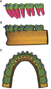
For developing the 3D finite-element model of the mandible, the outline of the teeth was obtained by 3D laser scanning of each of the mandibular right teeth of the Nissin teeth model (Model-i21D-400G; Nissin Dental Products, Kyoto, Japan), which was created via a sampling study of adults with normal occlusion. Referring to the studies of Coolidge14 and Kronfeld,15 the thickness of the periodontal ligament was uniformly modeled to 0.20 mm. After the alveolar bone was formed along the curvature of the cemento-enamel junction (CEJ) at a distance of 1 mm below the CEJ,16 a 3D finite-element model of the 14 teeth of the complete mandibular dentition, periodontal ligament, and alveolar bone was created ensuring left-right symmetry. In the finite-element model, the teeth, alveolar bone, bracket, and periodontal ligament were composed of tetrahedral elements with four nodes, the teeth and bracket were connected without interference, and the teeth were in contact with each other through the contact point as an independent object (Figure 1).
In this study, the teeth, alveolar bone, and periodontal ligament were assumed to be isotropic, homogeneous, linear elastic materials, and the material properties were assigned according to the studies of Tanne et al.,17 Jeong et al.,18 Chung et al.,19 Ziegler et al.,20 and Poppe et al.21 (Table 1). For finite-element analysis, the HP XW6400 workstation (Hewlett-Packard Co., Palo Alto, CA, USA) and ANSYS 11 (Swanson Analysis System, Canonsburg, PA, USA), which is a general-purpose finite-element analysis program, were used.
The dental arch form and tooth arrangement
Setting up the coordinate system
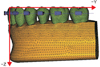
The midpoint of the line extending between the incisal edges of the two mandibular central incisors on both sides was set as the origin, the mediolateral direction as the X-axis, the labiolingual direction as the Y-axis, and the vertical direction as the Z-axis, in which the direction of the mandibular left central incisor was defined as +X, the labial direction as +Y, the apical direction as −Z, the lingual direction as −Y, and the XY plane as the occlusal plane of the teeth (Figure 2).
The dental arch form and arrangement
The dental arch form was arranged with reference to the broad arch form of Ormco® Inc. (Glendora, CA, USA), and the inclination and angulation of each tooth were arranged with reference to the studies of Andrews,22 Germane et al.23 and Park and Yang,24 without the Spee curve and Wilson curve (Figure 1).
Modeling the teeth group
Three groups were formed according to the number of teeth, i.e., the 4 mandibular anterior teeth group, the 6 mandibular anterior teeth group, and the complete mandibular dentition group. Each tooth was connected with the corresponding buccal and lingual arches. The material properties of the rigid body were assigned to the arch, and the brackets and buccal arch were connected by a complete coupling of two contact points to exclude any involvement of play. Along the apical (−Z) and lingual (−Y) directions from the origin of the coordinate system, the mandibular central incisors were connected with a rigid wire beam, to which an orthodontic force was applied. In order to prevent the occurrence of excessive elastic deformation in the mandibular central incisors connected with the rigid wire during the application of force and to ensure even distribution and delivery of force to all teeth belonging to each teeth group, the teeth were reinforced by connecting them with labial and lingual splint wires (Figures 2 and 3).
Investigation details and the conditions for force application
Analysis of the vertical center of resistance of the teeth groups
A 200-g retraction force was applied to the 4 mandibular anterior teeth group, 6 mandibular anterior teeth group, and complete mandibular dentition group. The forces were applied 0 mm, 5 mm, 10 mm, 15 mm, and 20 mm apically from the center of the incisal edge of the mandibular central incisors to the lingual direction (−Y). Within the predictable position for the center of resistance, the force was applied by subdividing it into 0.5-mm intervals.
Analysis of the horizontal (anteroposterior) center of resistance of the teeth groups
A 200-g intrusion force was applied to the 4 mandibular anterior teeth group, 6 mandibular anterior teeth group, and complete mandibular dentition group. For the 4 mandibular anterior teeth group and 6 mandibular anterior teeth group, the forces were applied 0 mm, −5 mm, −10 mm, −15 mm, and −20 mm along the Y-axis from the center of the incisal edge of the mandibular central incisors to the apical direction. For the complete mandibular dentition group, the forces were applied −20 mm, −25 mm, −30 mm, and −35 mm to the apical direction as well as the abovementioned positions. Within the predictable position for the center of resistance, the force was applied by sub-dividing it into 0.5-mm intervals.
The analysis method
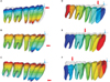
Because each tooth was independent and because a fine elastic deformation was observed in each tooth during force application in the finite-element model, all teeth belonging to each teeth group did not move equally in parallel. Therefore, in this study, the force application point that moved the teeth belonging to each teeth group as much as possible in parallel was defined as the center of resistance when the force was applied (Figure 4).
In order to examine the displacement of the tooth depending on the position of the applied force, nodal points were selected on the midpoint of the incisal edge or cusp tip and the root apex to interpret their movement as the movement of the tooth. The displacement of the selected node was represented along three directions (X-, Y-, and Z-axes), in which the displacement along each direction was assigned values of Δx, Δy, and Δz, respectively. The Δx, Δy, and Δz at the application point of each force were determined.
The vertical position of the center of resistance
When a retraction force was applied to a teeth group, all teeth in that group moved, and this was presented as displacement at the nodal point (the midpoint of the incisal edge, buccal cusp tip, or mesiobuccal cusp tip) selected for each tooth and the root apex (mesial root apex in molar). Anteroposterior changes in the position of the teeth (i.e., the selected nodal points) were represented as displacement along the Y-axis (Δy). If the displacement of the nodal point selected for each tooth and the displacement of the root apex were identical when the retraction force was applied, the tooth was considered to have moved in parallel to the posterior direction. Thus, the value obtained by subtracting Δy of the selected nodal point from the Δy of the root apex of each tooth was defined as the differential displacement. The position of force applied when the sum of the differential displacements obtained by adding up all the differential displacements of all teeth belonging to each teeth group became zero was determined to be the vertical position of the center of resistance.13
The horizontal (anteroposterior) position of the center of resistance
The horizontal position of the center of resistance of each teeth group was determined to be the position of the force applied when the vertical distance of the apical movement of the selected nodal points (the midpoint of the incisal edge, buccal cusp tip, or mesiobuccal cusp tip) of the teeth belonging to each teeth group was as uniform as possible on the application of an intrusion force. When the intrusion force was applied to each teeth group, vertical displacement was generated at the selected nodal points of the teeth, and this was represented as Δz along the Z-axis. When the values of Δz at the nodal points selected for each tooth were the same in all the teeth when the intrusion force was applied, i.e., when the standard deviations of Δz of each tooth were close to zero, the tooth in each teeth group was considered to have moved in parallel. Therefore, the position at which the intrusion force was applied when the standard deviation of Δz was closest to zero was determined to be the horizontal center of resistance of that teeth group.13
RESULTS
The position of the center of resistance of the 4 mandibular anterior teeth group
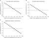
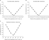
The vertical position of the center of resistance was the position where the sum of the differential displacements was close to zero; this position was 13.0 mm apical to the incisal edge of the mandibular central incisors (Figure 5). The anteroposterior position of the center of resistance was the position where the value of the standard deviation was minimum, and this was located 6.0 mm posterior to the incisal edge of the mandibular central incisors (Figure 6).
DISCUSSION
Bechtold et al.25 reported that while maxillary distalization using a single miniscrew led to maxillary distalization and a clockwise rotation in skeletal Class II treatment, the application of force in the direction of the maxillary center of resistance by using dual miniscrews led to both maxillary distalization and intrusion, which was a favorable outcome for such molar-related corrections. Moreover, Jing et al.26 reported that mandibular distalization using a miniscrew in skeletal Class III treatment led to a counterclockwise rotation of the occlusal plane and clockwise rotation of the mandible, which enabled treatment with esthetic and functional satisfaction without the need for surgery. As seen in these examples, the current widespread use of diverse TADs, the use of higher forces, and the availability of diverse directions for force application27 have enabled many treatments that were impossible in the past. Therefore, the identification of the exact position of the center of resistance has become ever more critical for predicting the movement and ensuring effective movement of teeth groups during treatment.12 Although many studies have investigated the position of the center of resistance, most of these studies have analyzed only the maxillary dentition, and very few studies have analyzed the mandibular dentition.
In their research on the center of resistance of an individual tooth, Burstone and Pryputniewicz28 reported that the position of the center of resistance of the tooth was in the cervical 1/3. Davidovitch and Rebellato29 indicated that the position of the center of resistance of the 6 mandibular anterior teeth group was at the cervical 1/3 of the mandibular canine root and Jing et al.26 indicated that the position of the center of resistance of the complete mandibular anterior dentition was between the first and second premolars. However, these studies merely indicated the approximate position of the center of resistance of the mandibular teeth groups rather than indicating the position as objective digitized values. Therefore, the purpose of the current study was to determine the position of the center of resistance more accurately by digitizing the position of the center of resistance of the mandibular teeth to facilitate its application in orthodontic treatment.
In the analysis of the center of resistance using finite-element analysis, Reimann et al.3 indicated the center of resistance as a range, and not a point. According to these authors, the size of the wire used to fix the teeth was reported to be related with the center of resistance, which is thought to be due to the effect of variables such as the play between the bracket and the wire and the deformation of the wire. Therefore, in the current study, material properties of the rigid body were assigned to the wire and no play between the bracket and the wire was allowed; the model was created to minimize those aspects. Despite the prediction in the investigation process that all teeth of the dentition group would move equally because of the retraction and intrusion forces, each tooth showed slightly different movement because of elastic deformation. Therefore, the position of the center of resistance was determined to be a position where the sum of the differential displacements of all teeth in the corresponding teeth group was close to zero or the standard deviation was the lowest.13
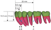
The results of this study showed that the position of the center of resistance of the 4 mandibular anterior teeth group was 13.0 mm apical and 6.0 mm posterior to the incisal edge of the mandibular central incisors. The position of the center of resistance of the 6 mandibular anterior teeth group was 13.5 mm apical and 8.5 mm posterior to the incisal edge of the mandibular central incisors. The position of the center of resistance of the complete mandibular dentition group was 13.5 mm apical and 25.0 mm posterior to the incisal edge of the mandibular central incisors (Figure 7). The position of the center of resistance of the mandibular teeth group obtained in this study appeared to be more apical than that of the maxillary teeth group obtained in the research by Jeong et al.13 Choy et al.30 showed that the center of resistance of a tooth is affected by the shape of the root. In the case of the anterior teeth, The roots of the maxillary anterior teeth were conical, their tapering became larger when moving from the cervical region to the root apex. However, the roots of the mandibular anterior teeth were cylindrical, the degree of tapering was weak. In the case of the premolar teeth, while the trunk region was well developed and could be divided into the buccal and palatal roots in the maxillary dentition, but only one root was present in the mandibular dentition. In addition, given that the maxillary molar has three roots and the mandibular molar has two, the cervical 1/3 region of the maxillary root is more developed, because it is likely to cause the center of resistance of the maxillary teeth group to be located in the border area of the cervical 1/3 and middle 1/3, and that of the mandibular teeth group to be in a more apical area. In terms of the anteroposterior position of the center of resistance, because the inclination of the maxillary anterior teeth is larger than that of the mandibular anterior teeth and because the size of the maxillary anterior teeth is larger than that of the mandibular anterior teeth, the position of the center of resistance is in the vicinity of the root of the second premolar tooth, but the center of resistance of the mandibular dentition seems to be located between the second premolar and the first molar.
A limitation of this finite-element analysis is that although it simulates the shape and mechanical properties of the corresponding object, it cannot reflect the biological response of the bone tissues over time. Moreover, this study focused on initial teeth displacement. Although the teeth groups were reinforced with rigid wires, initial elastic deformation of the teeth and alveolar bones could have affected the results. Given that the modeling was based on the average shape and size of teeth, the model may not help identify the exact center of resistance of an individual patient's dentition; nevertheless, the model is advantageous in that the conditions can be easily modified to draw valid conclusions.23
The effect of an orthodontic force applied using TADs on a tooth will be difficult to predict using traditional research methods. However, the use of finite-element models will be greatly helpful not only for identifying the center of resistance of the tooth, but also for inferring the expected displacement pattern of the tooth by applying the force in advance. Park et al.31 suggested that the skeletal patterns and degree of tooth exposure of the patient, as well as the desirable posttreatment occlusal plane, should be considered while planning the corrective improvement of deep bite. In addition, they used the most fundamental method for investigating mandibular anterior teeth intrusion by studying the amount of anterior inclination and stress distribution depending on the positions of the screw and application of intrusion force by using miniscrews for correcting the finite-element model during mandibular intrusion in the 4 and 6 mandibular anterior teeth. They suggested that miniscrews be placed distal to the lateral incisor in the 4 mandibular anterior teeth and distal to the canine in the 6 mandibular anterior teeth. The results of the present study were similar to those of Park et al.31 with regard to the location of the center of resistance of the 4 and 6 mandibular anterior teeth. Nowadays, many approaches are available for changing the occlusal plane in orthodontic treatment,222632 and these changes may require the application of greater force or the use of multiple TADs. In such cases, applying a force in advance by taking advantage of a finite-element model will help predict the movement of teeth, prevent incorrect movement of teeth, and facilitate more accurate and rapid treatment.
CONCLUSION
Finite-element analysis was useful in determining the 3D position of the center of resistance of the 4 anterior teeth group, the 6 mandibular anterior teeth group, and the complete mandibular dentition group, which was 13.0 mm apical and 6.0 mm posterior, 13.5 mm apical and 8.5 mm posterior, and 13.5 mm apical and 25.0 mm posterior, respectively, to the incisal edge of the mandibular central incisors.


 XML Download