Journal List > Korean J Orthod > v.47(3) > 1081224

Koo, Choi, Keum, Yu, Hwang, Melsen, and Lee: Maxillomandibular arch width differences at estimated centers of resistance: Comparison between normal occlusion and skeletal Class III malocclusion

Abstract

Objective

To evaluate the differences in maxillomandibular transverse measurements at either the crown or the estimated center of resistance (CR), and to compare values between normal occlusion and Class III malocclusion groups.

Methods

Dental casts and computed tomography (CT) data from 30 individuals with normal occlusion and 30 with skeletal Class III malocclusions were evaluated. Using the casts, dental arch widths (DAWs) were measured from the cusp tips, and basal arch widths (BAWs-cast) were measured as the distance between the points at the mucogingival junction adjacent to the respective cusp tips. The BAWs determined from CT (BAWs-CT) images were measured from the estimated CRs of the teeth.

Results

None of the DAW measurements or maxillomandibular DAW differences showed statistically significant intergroup differences. In contrast, the maxillary BAWs-CT and BAWs-cast were lesser in the Class III malocclusion group than in the normal occlusion group. The mandibular BAWs-CT were significantly greater in the Class III malocclusion group than in the normal occlusion group. Moreover, the maxillomandibular BAW differences on both CT and cast showed significant intergroup differences in all transverse measurements.

Conclusions

The maxillomandibular DAW differences showed no significant intergroup differences. In contrast, the maxillomandibular BAW differences on both CT and cast showed significant intergroup differences in all transverse measurements. The maxillomandibular BAW differences at the estimated CRs, measured using CT or casts, can reveal underlying transverse maxillary basal arch deficiencies in patients with skeletal Class III malocclusions.

INTRODUCTION

Nearly half of the patients with skeletal Class III malocclusions have maxillary skeletal retrusion, which contributes to transverse discrepancies between the maxilla and mandible.123 Hence, maxillary transverse deficiency is frequently addressed in these patients. Uysal et al.4 reported that the maxillary interpremolar, intermolar, and all of the maxillary alveolar widths were significantly narrower in patients with Class III malocclusions than in individuals with normal occlusion. Therefore, to ensure appropriate treatment and stability after orthodontic and/or orthognathic surgery in patients with Class III malocclusions, the presence of transverse discrepancy, not just the disharmonies in the sagittal and vertical dimension should be identified.
To date, posteroanterior cephalograms have been widely used for transverse skeletal analysis. Although cephalograms enable the measurement of basal bone widths at the jugal points and antegonial notches, they provide a poor representation of alveolar bone width, especially in the mandible.56 Additionally, conventional two-dimensional radiographs have some limitations, including image magnification and projection errors, due to the rotation of the head.78 For transverse dental analysis, casts have been used to measure intercanine and intermolar widths between the cusp tips or the fossae. However, in this method, dentoalveolar compensation could mask the underlying transverse deficiencies in patients with Class III malocclusions. Previous studies have shown significant buccal tipping of the maxillary molars coupled with lingual tipping of the mandibular molars on the side to which the mandible shifted in adult patients with skeletal Class III malocclusions who required orthognathic surgery.910
The center of resistance (CR), or centroid, represents the center of gravity in a restrained body; it is considered a reasonable landmark to define tooth position and its displacement.11121314 Unlike the cusp tips or root apices, the CR is not readily affected by the simple tilting movement of a tooth. Many previous studies have used the location of CR points determined from lateral cephalograms for evaluating tooth movement along the sagittal plane.111215 Unfortunately, using the location of CR points on posteroanterior cephalograms to analyze the transverse dimension is not feasible due to overlapping structures in the posterior teeth area of the image. Recent attempts to overcome this issue include the use of three-dimensional computed tomography (3D CT). Distortion-free slice images may be used effectively to locate CR points for evaluating transverse discrepancies between the maxillary and mandibular basal arch widths (BAWs).
Therefore, the aim of this study was to evaluate the maxillomandibular transverse differences measured at either the crown or the estimated CR, and to compare these values between individuals with normal occlusion and patients with Class III malocclusions.

MATERIALS AND METHODS

Subjects

A priori power analysis suggested that 30 subjects were required to achieve a power level of 80% with an α significance level of 0.05. The dental casts, cephalograms, and CT images from 30 subjects (20 men and 10 women) exhibiting normal occlusion and skeletal Class I relationships were retrieved from the archives at Yonsei University in Seoul, Korea.16 The patients in the normal occlusion group had been included in previous studies, and their ages ranged from 21 to 30 years (mean age, 22.7 years). The Class III malocclusion group included 30 patients (17 men and 13 women) with skeletal Class III malocclusions and severe mandibular prognathism, retrospectively selected from among the orthognathic surgery cases in the Department of Orthodontics, Yonsei Dental Hospital in Seoul, Korea. Their ages ranged from 19 to 34 years (mean age, 21.6 years). The study protocol conformed to the Declaration of Helsinki and was approved by the Institutional Review Board of Yonsei Dental Hospital (IRB No. 2-2015-0012).
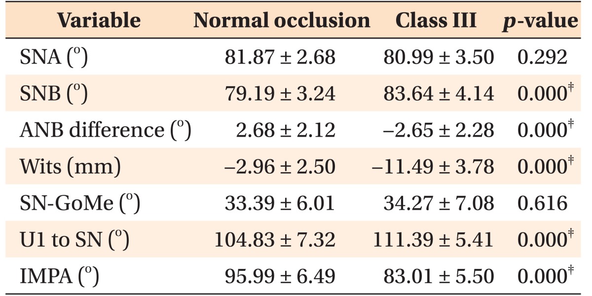
Patients with marked dental asymmetry, including a menton deviation greater than 4 mm and occlusal canting greater than 4°, were excluded from the study. The inclusion criteria for both groups were as follows: 1) all permanent teeth, including the second molars, were present and fully erupted; 2) crowding of less than 3 mm existed in each arch; 3) no history of orthodontic treatment; and 4) no severe dental anomalies of the crown/root shape. The cephalometric measurements collected from the subjects in the two groups are displayed in Table 1. The dental casts, cephalograms, and CT images of patients with Class III malocclusions were obtained to establish orthodontic and surgical treatment plans on an intend-to-treat basis.

Cast measurements

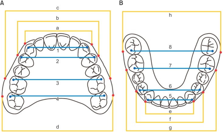
All cast measurements for assessing the dental arch width (DAW) and BAW-cast were obtained using digital calipers (Mitutoyo Corporation, Kawasaki, Japan). The DAWs were measured at the respective cusp tips, and the BAWs-cast measured the distance between the points at the mucogingival junction above the respective cusp tips. The DAW and BAW-cast measurements are shown in Figure 1.

CT measurements

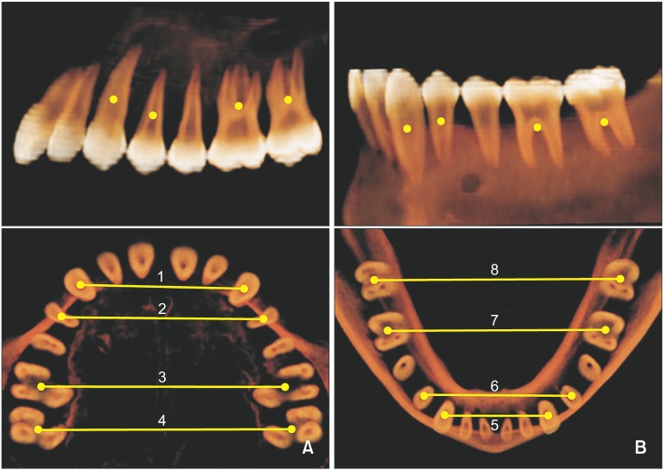
Three-dimensional X-ray images were obtained using a high-speed helical CT scanner (HiSpeed Advantage; GE Medical System, Milwaukee, WI, USA), programmed at 120 kVp and 180 mA. The digital imaging and communications in medicine (DICOM) images were created with a 1.0-mm slice thickness after scanning and were imported to a dental software program (InVivoDental® version 5.1; Anatomage, San Jose, CA, USA). Based on the findings of previous studies,1315 we determined the BAWs from the CT scans (BAWs-CT) by digitizing the estimated CR at the level of the coronal one-third for a single rooted tooth and at the furcation for a multirooted tooth. Positions of the estimated CRs were pinpointed on the axial, sagittal, and coronal sections by using a slice locator in the InVivoDental® software program (Figure 2). The CT measurements were calibrated using a dry skull, as described in a previous study.16

Reliability

One trained and calibrated investigator conducted the repeated measurements for each variable, with a two-week interval between measurements, from 15 randomly selected dental casts and 15 randomly selected CT images. Method error was calculated using Dahlberg's formula.

Statistical analysis

All statistical analyses were performed using IBM SPSS Statistics version 20.0 (IBM Co., Armonk, NY, USA). The Shapiro-Wilk test was used to verify the normality of data distribution. Independent t-test was applied for comparison of the DAW, BAW-CT, and BAW-cast values between the normal occlusion and skeletal Class III malocclusion groups. Statistical significance was set at the 5% level.

RESULTS

In this study, the method errors ranged from 0.21 to 0.53 mm for linear measurements. A Mann-Whitney U-test was conducted to investigate sex differences in each group. The results showed that except for the DAWs and BAWs of the maxillary premolars, the transverse measurements in the two groups revealed no significant sex differences. Therefore, errors caused by gender difference were considered minimal in this study.
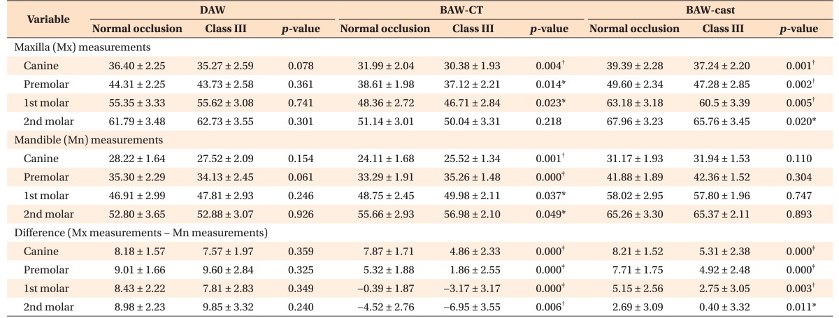
Table 2 summarizes the transverse measurements in each group, including the DAWs, BAWs, and their differences between the maxilla and mandible. None of the individual DAW measurements or maxillomandibular DAW differences showed statistically significant intergroup differences. In contrast, the maxillary BAWs-CT were lesser in the Class III malocclusion group than in the normal occlusion group (p < 0.01 for canines; p < 0.05 for premolars and first molars). The maxillary BAWs-cast were also lesser in the Class III malocclusion group than in the normal occlusion group (p < 0.01 except for second molars; p < 0.05 for second molars). In addition, all the mandibular BAWs-CT were significantly greater in the Class III malocclusion group than in the normal occlusion group (p < 0.01 for canines and premolars, p < 0.05 for first and second molars). In contrast, none of the mandibular BAWs-cast showed statistically significant intergroup differences. The maxillomandibular BAW differences on both CT images and casts showed significant intergroup differences in all transverse measurements (p < 0.05).
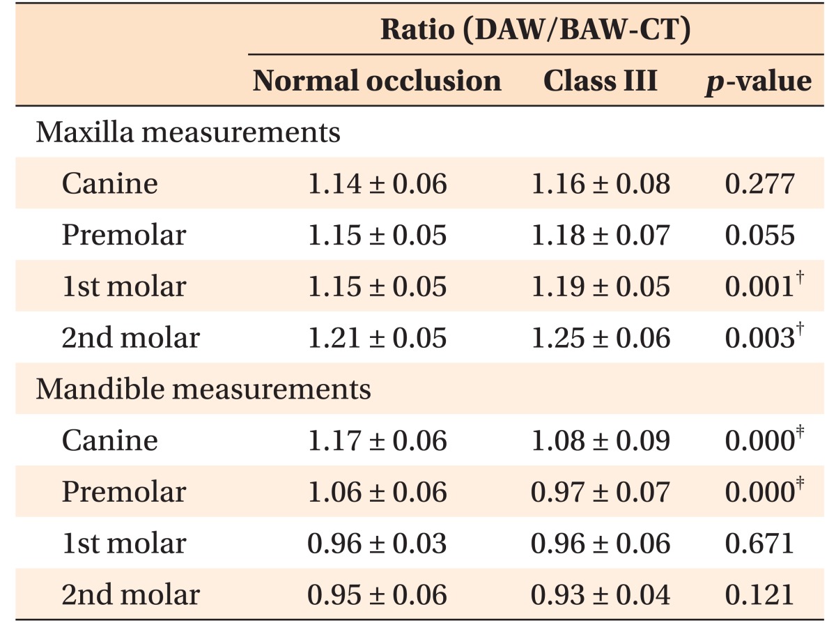
The ratios between the DAW and BAW-CT reflect the degree of transverse dental compensation (Table 3). Compared to the normal occlusion group, the Class III malocclusion group showed significantly larger ratios in the maxillary molar area and significantly smaller ratios in the mandibular canine and premolar areas (p < 0.01).

DISCUSSION

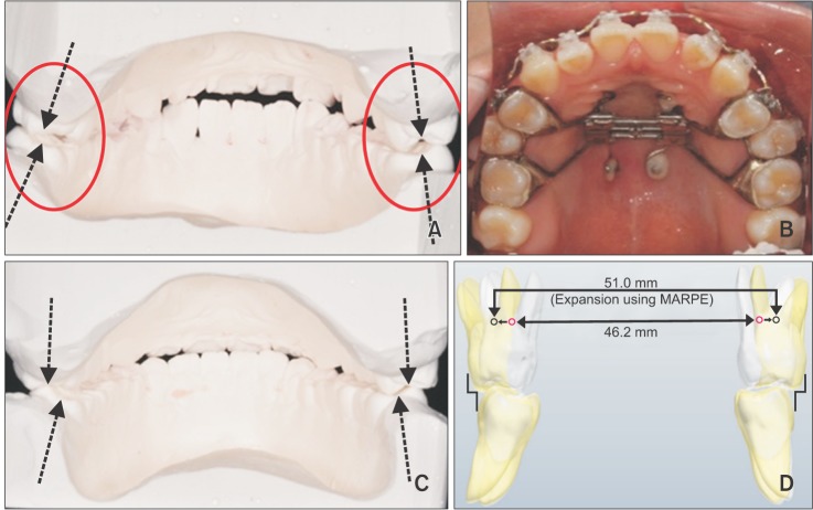
Appropriate diagnostic methods are required to define underlying transverse discrepancies. Undetected maxillary constriction, for instance, may lead to an inadequate and unstable buccal relationship and may adversely affect the periodontal tissue towards the end of treatment.17 Figure 3 shows that transverse dental compensation can mask the underlying transverse deficiency.18
It is of foremost importance to access the balance in the maxillomandibular transverse dimension in each individual case in order to establish a desirable occlusal scheme. However, few studies have investigated the appropriate maxillary and mandibular basal arch dimensions in the normal occlusion and/or Class III malocclusion groups. In particular, the transverse relationship in the second molar area has been difficult to define.
The datasets used in this study were from two sources: the DAWs and BAWs-cast were obtained from dental casts and BAWs-CT from CT images. Lim and Lim19 found no significant differences between dental measurements obtained from plaster models and those from CT images obtained with the mouth open, suggesting that CT image analysis could replace plaster model analysis. However, the present study used CT images acquired at the position of maximum intercuspation, where the density of teeth and streak artifacts from minor dental restorations could affect the accuracy of dental landmarks.20 Therefore, additional calibration was performed for the measurements obtained from CT images.
The transverse dental dimension in patients with Class III malocclusions and those with normal occlusion varies between studies. Kuntz et al.21 demonstrated smaller maxillary molar DAWs in patients with Class III malocclusions than in those with normal occlusion. In contrast, Lee and Son22 reported that the ratios of the mandibular DAWs to the maxillary DAWs were not significantly different between the two groups, because the DAWs of the Class III malocclusion group were well compensated. The present study also showed no significant differences in DAWs between the Class III malocclusion and normal occlusion groups, indicating that the arch dimension is affected by the degree of compensation. Therefore, a comparison of the maxillomandibular differences in the basal bone area may have more clinical significance.
In this study, the BAWs showed remarkable differences in the group comparison (Table 2). With the exception of the second molar location, the maxillary BAWs-CT and all of the maxillary BAWs-cast were significantly lesser in the Class III malocclusion group than in the normal occlusion group. In addition, all of the mandibular BAWs-CT were significantly greater in the Class III malocclusion group than in the normal occlusion group. However, none of the mandibular BAWs-cast showed statistically significant intergroup differences. This finding is supported by a previous study that showed no significant difference in BAWs between the normal occlusion and Class III malocclusion groups in the mandibular first molar area.21 However, transverse analysis of the basal bone on the dental cast is known to be hindered by the presence of bones of varying thicknesses and soft tissues covering the roots, depending on the vertical facial pattern and/or masticatory function.23 To overcome these limitations, Suk et al.24 introduced root center points, similar to the CRs, to evaluate the mandibular arch form. However, the authors admitted that the root center points could only be used in the flat occlusal plane. Therefore, estimated CR has been suggested for the use in transverse dental analysis to help understand occlusal phenotypes. Use of estimated CR may enable area-specific evaluation of the transverse dimension at the basal bone level, regardless of the thickness of the buccal plate and the flatness of the occlusal plane.
In the normal occlusion group, the maxillomandibular DAW differences were relatively uniform, ranging from 8.18 to 9.01 mm (Table 2). The Class III group also did not show significant differences in the maxillomandibular DAW differences compared to the normal occlusion group. However, this study indicated that the maxillomandibular BAW-CT differences were significantly greater in the Class III malocclusion group than in the normal occlusion group both at the first and second molars, thereby implying a possible inherent transverse discrepancy in the skeletal Class III malocclusion group.
Unlike the relatively large differences in DAWs, the maxillomandibular BAW-CT difference at the first molar was −0.39 ± 1.87 mm in the normal occlusion group. This suggests that the CRs of the first molars are aligned along the vertical axes of occlusion, and facilitate the distribution of masticatory load through the stress trajectories.25 In this context, the maxillomandibular BAW-CT difference at the second molar (−4.52 ± 2.76 mm) in the normal occlusion group is somewhat striking. However, to date, very few studies have calculated the transverse basal dimension in the second molar area, possibly due to technical limitations using the dental casts.3 These measurements may reflect an inherent transverse deficiency in the rearmost area, despite the adequate dimension in the first molar area. This presumably substantiates the frequent occlusal aberration at the second molar, such as buccal crossbite, and the non-working side interferences caused by the prominent palatal cusp tip of the second molar.3
The ratios between DAWs and BAWs-CT reflected the degree of transverse compensation. The ratios indicated that even without an obvious transverse discrepancy, an underlying basal discrepancy may exist, particularly in patients with skeletal Class III malocclusions. In the Class III malocclusion group, transverse compensation of the molars occurred in the maxilla mainly by buccal tipping (Table 3). According to the equilibrium theory, the position of the tooth is determined by the resting pressure of the buccolingual soft tissue.26 This notion was shown to be associated with the posture of the tongue.27 Previous reports have speculated that gradual forward growth of the mandible contributes to the increase in the lateral tongue dimensions, which in turn may cause narrowing of the maxillary basal bone and inhibit lingual tipping of the mandibular molars.28 Therefore, more frequent orthodontic and/or surgical intervention to achieve maxillary expansion may be required for establishing normal transverse occlusion in patients with Class III malocclusions. As shown in Figure 4, in patients with severe Class III malocclusions, accurate diagnosis is crucial to determine the need for active transverse correction of the basal bone by using treatment modalities such as surgically assisted or nonsurgical palatal expansion or segmental surgery.2930
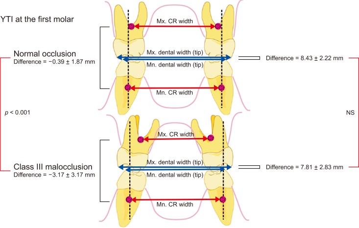
The results from this study suggests that when the maxillomandibular BAW-CT difference (−0.39 ± 1.87 mm) and BAW-cast difference (5.15 ± 2.56 mm) of the first molar are taken together into consideration, they can provide a useful index (Yonsei Transverse Index) for assessing the transverse relationship between the maxilla and mandible regardless of the presence of an abnormal occlusal phenotype (Figure 5). Additionally, since this study focused mainly on the relationship between anteroposterior and transverse discrepancies, further studies are required to identify additional factors affecting the transverse dimension, for example, the vertical facial pattern.

CONCLUSION

None of the DAW measurements or maxillomandibular DAW differences showed statistically significant intergroup differences. However, the maxillomandibular BAW differences on both CT and cast showed significant intergroup differences in all transverse measurements. In the Class III malocclusion group, the maxillomandibular transverse differences measured at the estimated CR were greater than those measured at the estimated crown level. Therefore, in order to accurately define the underlying transverse discrepancy especially in the skeletal Class III malocclusion group, we recommend the use of maxillomandibular transverse differences measured at the estimated CR by using CT or casts. This is because the transverse dental decompensation of the molar would occur in the form of rotation around the center of rotation near its CR by a moment during alignment with rectangular wire. Additionally, we suggest combined evaluation of both maxillomandibular BAW-CT difference (−0.39 ± 1.87 mm) and BAW-cast difference (5.15 ± 2.56 mm) of the first molar, as the Yonsei Transverse Index, for accurate diagnosis of the underlying maxillomandibular transverse discrepancy.

Notes

This study was supported by a research grant from the College of Dentistry, Yonsei University, 2009 (6-2009-0142).

The authors report no commercial, proprietary, or financial interest in the products or companies described in this article.

References

1. Franchi L, Baccetti T. Transverse maxillary deficiency in Class II and Class III malocclusions: a cephalometric and morphometric study on postero-anterior films. Orthod Craniofac Res. 2005; 8:21–28. PMID: 15667642.
crossref
2. Proffit WR, Phillips C, Prewitt JW, Turvey TA. Stability after surgical-orthodontic correction of skeletal Class III malocclusion. 2. Maxillary advancement. Int J Adult Orthodon Orthognath Surg. 1991; 6:71–80. PMID: 1811032.
3. McNamara JA. Maxillary transverse deficiency. Am J Orthod Dentofacial Orthop. 2000; 117:567–570. PMID: 10799117.
4. Uysal T, Usumez S, Memili B, Sari Z. Dental and alveolar arch widths in normal occlusion and Class III malocclusion. Angle Orthod. 2005; 75:809–813. PMID: 16279827.
5. Ricketts RM. Perspectives in the clinical application of cephalometrics. The first fifty years. Angle Orthod. 1981; 51:115–150. PMID: 6942666.
6. Hesby RM, Marshall SD, Dawson DV, Southard KA, Casko JS, Franciscus RG, et al. Transverse skeletal and dentoalveolar changes during growth. Am J Orthod Dentofacial Orthop. 2006; 130:721–731. PMID: 17169734.
crossref
7. Leonardi R, Annunziata A, Caltabiano M. Landmark identification error in posteroanterior cephalometric radiography. A systematic review. Angle Orthod. 2008; 78:761–765. PMID: 18302479.
8. Jung PK, Lee GC, Moon CH. Comparison of cone-beam computed tomography cephalometric measurements using a midsagittal projection and conventional two-dimensional cephalometric measurements. Korean J Orthod. 2015; 45:282–288. PMID: 26629474.
crossref
9. Kusayama M, Motohashi N, Kuroda T. Relationship between transverse dental anomalies and skeletal asymmetry. Am J Orthod Dentofacial Orthop. 2003; 123:329–337. PMID: 12637905.
crossref
10. Tyan S, Park HS, Janchivdorj M, Han SH, Kim SJ, Ahn HW. Three-dimensional analysis of molar compensation in patients with facial asymmetry and mandibular prognathism. Angle Orthod. 2016; 86:421–430. PMID: 26192894.
crossref
11. Burstone CR. Deep overbite correction by intrusion. Am J Orthod. 1977; 72:1–22. PMID: 267433.
crossref
12. Melsen B, Agerbaek N, Markenstam G. Intrusion of incisors in adult patients with marginal bone loss. Am J Orthod Dentofacial Orthop. 1989; 96:232–241. PMID: 2773869.
crossref
13. Smith RJ, Burstone CJ. Mechanics of tooth movement. Am J Orthod. 1984; 85:294–307. PMID: 6585147.
crossref
14. Jo AR, Mo SS, Lee KJ, Sung SJ, Chun YS. Finite-element analysis of the center of resistance of the mandibular dentition. Korean J Orthod. 2017; 47:21–30. PMID: 28127536.
crossref
15. van Steenbergen E, Burstone CJ, Prahl-Andersen B, Aartman IH. Influence of buccal segment size on prevention of side effects from incisor intrusion. Am J Orthod Dentofacial Orthop. 2006; 129:658–665. PMID: 16679206.
crossref
16. Lee KJ, Joo E, Kim KD, Lee JS, Park YC, Yu HS. Computed tomographic analysis of tooth-bearing alveolar bone for orthodontic miniscrew placement. Am J Orthod Dentofacial Orthop. 2009; 135:486–494. PMID: 19361735.
crossref
17. Vanarsdall RL Jr. Transverse dimension and long-term stability. Semin Orthod. 1999; 5:171–180. PMID: 10860069.
crossref
18. Burstone CJ, Choy K. The biomechanical foundation of clinical orthodontics. Chicago: Quintessence Publishing Co, Inc.;2015.
19. Lim MY, Lim SH. Comparison of model analysis measurements among plaster model, laser scan digital model, and cone beam CT image. Korean J Orthod. 2009; 39:6–17.
crossref
20. Barrett JF, Keat N. Artifacts in CT: recognition and avoidance. Radiographics. 2004; 24:1679–1691. PMID: 15537976.
crossref
21. Kuntz TR, Staley RN, Bigelow HF, Kremenak CR, Kohout FJ, Jakobsen JR. Arch widths in adults with Class I crowded and Class III malocclusions compared with normal occlusions. Angle Orthod. 2008; 78:597–603. PMID: 18302456.
crossref
22. Lee HK, Son WS. A study on basal and dental arch width in skeletal class III malocclusion. Korean J Orthod. 2002; 32:117–127.
23. Masumoto T, Hayashi I, Kawamura A, Tanaka K, Kasai K. Relationships among facial type, buccolingual molar inclination, and cortical bone thickness of the mandible. Eur J Orthod. 2001; 23:15–23. PMID: 11296507.
crossref
24. Suk KE, Park JH, Bayome M, Nam YO, Sameshima GT, Kook YA. Comparison between dental and basal arch forms in normal occlusion and Class III malocclusions utilizing cone-beam computed tomography. Korean J Orthod. 2013; 43:15–22. PMID: 23504406.
crossref
25. Robert WE. Bone physiology, metabolism, biomechanics in orthodontic practice. In : Graber LE, Vanarsdall RL, Vig KW, editors. Orthodontics: current principles and techniques. 5th ed. Philadelphia, PA: Elsevier/Mosby;2012.
26. Proffit WR. Equilibrium theory revisited: factors influencing position of the teeth. Angle Orthod. 1978; 48:175–186. PMID: 280125.
27. Ovsenik M, Primožič J. How to push the limits in the transverse dimension? Facial asymmetry, palatal volume and tongue posture in children with unilateral posterior cross bite: a three-dimensional evaluation of early treatment. Orthod Fr. 2014; 85:139–149. PMID: 24923214.
28. Braun S, Hnat WP, Fender DE, Legan HL. The form of the human dental arch. Angle Orthod. 1998; 68:29–36. PMID: 9503132.
29. Choi SH, Shi KK, Cha JY, Park YC, Lee KJ. Nonsurgical miniscrew-assisted rapid maxillary expansion results in acceptable stability in young adults. Angle Orthod. 2016; 86:713–720. PMID: 26938955.
crossref
30. Lee KJ, Park YC, Park JY, Hwang WS. Miniscrew-assisted nonsurgical palatal expansion before orthognathic surgery for a patient with severe mandibular prognathism. Am J Orthod Dentofacial Orthop. 2010; 137:830–839. PMID: 20685540.
crossref
Figure 1

Dental arch width on cast (DAW). A, Maxilla: 1, canine; 2, premolar; 3, 1st molar; 4, 2nd molar. B, Mandible: 5, canine; 6, premolar; 7, 1st molar; 8, 2nd molar. Basal arch width on cast (BAW-cast). A, Maxilla: a, canine; b, premolar; c, first molar; d, second molar. B, Mandible: e, canine; f, premolar; g, first molar; h, second molar.

kjod-47-167-g001
Figure 2

Basal arch width on three-dimensional computed tomography (BAW-CT). The digitization of centers of resistance: a single-rooted tooth, at the level of the coronal one-third; a multirooted tooth, at the level of the furcation. A, Maxilla: 1, canine; 2, premolar; 3, 1st molar; 4, 2nd molar. B, Mandible: 5, canine; 6, premolar; 7, 1st molar; 8, 2nd molar.

kjod-47-167-g002
Figure 3

Dental compensation of the maxillary and mandibular posterior teeth. A, A patient exhibiting a constricted mandibular arch with several lingually tilted posterior teeth at initial treatment. B, An end-to-end relationship on the left second molar side is shown after alignment. Red circle indicates estimated center of resistance. C, The superimposition via three-dimensional (3D) rendering shows the changes in the transverse molar relationship before (white) and after (yellow) alignment. Unknown moment on the maxillary and mandibular first molars resulted in uncontrolled rotation, leading to iatrogenic transverse dental decompensation. No differences were observed in the BAW-CT of both the arches at the first molar before and after alignment using a rectangular wire. Purple circle, the estimated center of resistance of the maxillary and mandibular first molar.

BAW-CT, Basal arch width on the computed tomography image.
kjod-47-167-g003
Figure 4

Correction of the maxillary basal arch width (BAW) by using a miniscrew-assisted rapid palatal expansion appliance (MARPE). A, A patient exhibiting a constricted maxillary arch and initial transverse dental compensation of the maxillary posterior teeth. B, MARPE is used to expand the maxillary BAW. C, The posttreatment dental cast shows that ideal occlusion was established with the proper long axis of the maxillary posterior teeth. D, The superimposition via three dimensional rendering shows that the maxillary (BAW-CT) at the first molar was corrected from 46.2 to 51.0 mm before (white) and after treatment (yellow), respectively. The estimated center of resistance of the maxillary first molar displaced before (purple circle) and after treatment (gray circle) using MARPE.

kjod-47-167-g004
Figure 5

A schematic diagram for the Yonsei Transverse Index (YTI).

Mx., Maxilla; Mn., mandible; CR, center of resistance; NS, not significant.
kjod-47-167-g005
Table 1

Sample characteristics of the normal occlusion and Class III malocclusion groups

kjod-47-167-i001

Values are presented as mean ± standard deviation.

p-values were calculated using independent t-tests.

SNA, Sella-nasion-A point angle; SNB, sella-nasion-B point angle; ANB, A point-nasion-B point angle; SN-GoMee, SN plane-mandibular plane angle; IMPA, incisor mandibular plane angle.

p < 0.001.

Table 2

DAWs and BAWs of the normal occlusion and Class III malocclusion groups (unit: mm)

kjod-47-167-i002

Values are presented as mean ± standard deviation.

DAW, Dental arch width; BAW-cast, basal arch width on the cast; BAW-CT, basal arch width on the computed tomography image.

p-values were calculated using independent t-tests.

*p < 0.05; p < 0.01; p < 0.001.

Table 3

The ratios between DAW and BAW-CT in the normal occlusion and Class III malocclusion groups

kjod-47-167-i003

Values are presented as mean ± standard deviation.

DAW, Dental arch width; BAW-CT, basal arch width on the computed tomography image.

p-values were calculated using independent t-tests.

p < 0.01; p < 0.001.

TOOLS
Similar articles