

 PDF
PDF ePub
ePub Citation
 Print
Print


INTRODUCTION
Miniscrews have been used to provide temporary skeletal anchorage during orthodontic treatment. Miniscrews have several advantages including small size, easy insertion and removal, and relatively low cost, which enable them to be placed in various areas without damaging anatomic structures; moreover, they can be loaded immediately after insertion.12
However, the miniscrew success rate in clinical practice has been reported to range from 83.9% to 93.3%.356 Various factors have been reported to influence miniscrew stability, including design (tapered or cylindrical),78 diameter,9 surface treatment,1011 cortical bone thickness,1213 implantation location,314 and insertion angle.1516
To prevent root injury, Kyung et al.17 recommended miniscrew insertion at angles of 30° to 40° in the maxilla and 10° to 20° in the mandible rather than perpendicular to the bone surface. Previous studies have also suggested that insertion angles between 50° and 70° might be advisable to achieve greater miniscrew stability under loading conditions.1819 Other researchers have reported that placing miniscrews at a 90° angle to the bone surface reduced the stress concentration, and that placing miniscrews at angles less than 90° to the alveolar process surface did not offer advantages in terms of anchorage resistance force.151620 However, these studies were performed with a single type of miniscrew, and only stress distributions adjacent to alveolar bone were investigated.
The purpose of this study was to analyze stress distributions in the roots, periodontal ligaments (PDLs), and bone around the miniscrew resulting from the insertion of cylindrical and tapered miniscrews at different angles using a finite element analysis. The null hypothesis was that the stress distributions in the roots, PDL, and bone would be similar between cylindrical and tapered miniscrews during miniscrew insertion and en masse retraction of anterior teeth, regardless of insertion angle.
MATERIALS AND METHODS
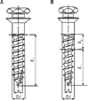
A maxilla model of a dentition with extracted first premolars was obtained via three-dimensional (3D) laser scanning of a normal adult occlusion model (Nissin Dental Products, Kyoto, Japan). The 3D models of the cylindrical and tapered miniscrews were based on computer-aided design data from 1508C and 1508T screws (orthodontic Ti-6Al-4V miniscrews; diameter, 1.45 mm; length, 8 mm; single-threaded; Biomaterials Korea, Seoul, Korea) using HyperWorks version 8.0 software (Altair, Troy, MI, USA) (Figure 1, Table 1).
The dental arch form was arranged in accordance with a broad arch form provided by the Ormco Corporation (Orange, CA, USA), and all teeth were aligned with respect to the facial axis point according to Andrews.21 The curves of Spee and Wilson were not added.
The PDLs were modeled based on the exterior geometries of the roots. Based on studies by Kronfeld22 and Coolidge,23 PDL thickness was set at 0.25 mm throughout, although it differs according to age, tooth type, and individual variation. The alveolar bone was assumed to be normal and was formed 1 mm below the cementoenamel junction (CEJ), as dictated by the shape of the CEJ. The thickness of the cortical bone was set at 1.5 mm.
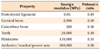
The model was meshed automatically with a 4-node tetrahedral element. Approximately 86,300 nodes and 461,400 elements were used in the model construction. The bone, teeth, PDLs, and miniscrews were all defined as linearly elastic, homogeneous, and isotropic materials. Although values for the Young's modulus and Poisson's ratio of the PDL vary widely according to references, the Young's modulus and Poisson's ratio for the PDL, bone, teeth, miniscrew, bracket, and wire in the present study followed those of previous studies on the en masse retraction of anterior teeth using miniscrews in sliding mechanics (Table 2).1524 Especially, the PDL was assumed to behave isotropically and symmetrically under compression and tension conditions. Of course, this does not reflect the PDL's complex structure and behavior perfectly. However, this assumption was sufficient to describe initial tooth movements under orthodontic loading conditions.25
To ensure the convergence of the finite element model, 0.8 mm was determined as an appropriate mesh element size for all mesh models. All interfaces between the teeth, PDLs, bone, and miniscrews were assumed to be bonded. The proximal and distal bone surfaces were fixed in all directions as boundary conditions.
It was assumed that each miniscrew was inserted 6 mm above the alveolar crest in the interradicular space between the maxillary second premolar and maxillary first molar. The tooth axes of the second premolar and first molar were assumed to be parallel to each other and perpendicular to the occlusal plane. The distance between the center of the miniscrew and root surface was 1.5 mm. A flat bone surface without curvature was assumed at the insertion site.
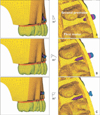
The miniscrews were inserted at 30°, 60°, and 90° angles to the bone surface. The miniscrew insertion was designed such that the cortical bone would cover all miniscrew threads when the miniscrew was inserted at 90° to the bone surface. This meant that portions of the screw threads were exposed at other insertion angles. For the 30° and 60° insertion angles, the miniscrew head was oriented towards the occlusal plane (Figure 2).
Because of technical difficulties in reproducing the drilling process in the finite element analysis, a 1.2-mm diameter hole was formed in the bone. Thereafter, a 1.45-mm diameter miniscrew was seated in the hole. An external force was not applied when placing miniscrews into the holes in the bone. The stress distribution during miniscrew insertion was measured when the hole 1.2 mm in diameter was expanded by a miniscrew 1.45 mm in diameter. It was assumed that there was no stress in the peri-miniscrew area prior to applying a horizontal force to the inserted miniscrew.
After miniscrew insertion, a horizontal force of 2 N pulling mesially was applied at the top surface of the miniscrew parallel to the occlusal plane to simulate an en-masse retraction of anterior teeth based on previous studies.2627
The von Mises stresses were measured in the roots and PDLs of the maxillary second premolars, first molars, cortical bone, and cancellous bone during miniscrew insertion and after orthodontic force loading at placement angles of 30°, 60°, and 90°.
RESULTS
Stress during miniscrew insertion
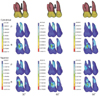
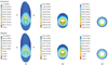
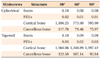
Roots (Table 3, Figure 3)
For both types of miniscrews, the maximum von Mises stresses occurred at the center of the furcation of the first molar root. The maximum von Mises stresses from tapered miniscrews were greater than those from cylindrical miniscrews at all insertion angles, but the differences were not clinically important.
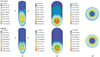
PDLs (Table 3, Figure 4)
The maximum von Mises stress occurred in the mesiobuccal root of the maxillary first molar. As the insertion angle was reduced, the maximum von Mises stresses for both miniscrew types moved toward the buccal side of the maxillary first molar. The maximum von Mises stresses of tapered miniscrews were greater than those of cylindrical miniscrews at all insertion angles, but the differences were not clinically important.
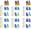
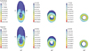
Cortical bone (Table 3, Figure 5)
For both types of miniscrews, von Mises stress distributions were observed continuously at the cortical bone peripheries proximal to the 90° miniscrew insertion sites. The maximum von Mises stresses of cylindrical miniscrews increased as insertion angle decreased. The von Mises stresses of tapered miniscrews were greatest at 30° and least at 60°. Tapered miniscrews exhibited greater maximum von Mises stresses than cylindrical miniscrews.
Stress distributions during force application
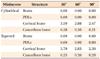
Roots and PDLs (Table 4)
The maximum von Mises stresses from cylindrical and tapered miniscrews were near zero, regardless of insertion angle.
Cortical bone (Table 4, Figure 7)
For both miniscrew types, the maximum von Mises stresses occurred on the mesial side of the cortical bone near the miniscrew at 90°; maximum von Mises stresses increased as insertion angle decreased. Cylindrical miniscrews exhibited greater von Mises stresses than tapered miniscrews at 60° and 90°, but the differences were not clinically important.
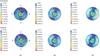
Cancellous bone (Table 4, Figure 8)
For both types of miniscrews, the maximum von Mises stresses at 60° were larger than those observed at other angles. Cylindrical miniscrews exhibited higher von Mises stresses than tapered miniscrews regardless of insertion angle, but the differences were not clinically important.
DISCUSSION
Increasing the diameter of a miniscrew increases primary stability more effectively than increasing length.9 However, a larger screw diameter can limit placement options because of root proximity. Therefore, various tapered miniscrews have been designed to solve this problem. A tapered miniscrew can increase primary stability by inducing a controlled compressive force in the cortical bone.28 However, excessive insertion torque may cause deformations in the surrounding bone that result in congestion and necrosis at the bone interface.2930 Increased deformation from excessive stress might attract more inflammatory mediators to the site and could possibly result in bone resorption and remodeling, which may cause miniscrew failure.15
In this study, tapered miniscrews demonstrated maximum von Mises stresses twice as large as cylindrical miniscrews at 90° during placement in cortical bone. In contrast, there was no difference in maximum von Mises stresses during force application between the 2 groups. This result suggests that the anchorage resistances of these types of miniscrews were not different. Cha et al.7 reported that tapered miniscrews exhibited greater mean initial and removal torques than cylindrical miniscrews until 3 weeks, but there was no difference in secondary stability in Beagle dogs. Yoo et al.28 also reported that tapered miniscrews exhibited greater initial stability than cylindrical miniscrews; however, the clinical success rates and removal torques of the 2 designs were similar in clinical practice.
In this study, the maximum von Mises stresses increased as insertion angle decreased during miniscrew placement and with horizontal force application to inserted miniscrews in both groups. The stresses in cortical and cancellous bone were lowest for miniscrews placed at 90° to the bone surface, regardless of miniscrew design. Deguchi et al.31 reported that compared with placing miniscrews perpendicular to the long axis of the tooth, placing the miniscrew at a 30° angle increased the contact area with cortical bone by as much as 1.5-fold. If the insertion angle is small, the contact area between the miniscrew and cortical bone increases, but the stress between the screw and cortical bone appears to increase regardless of miniscrew type. This finding is consistent with the results of previous studies151620 demonstrating that maximum von Mises stresses in miniscrews and cortical bone decreased as insertion angle increased. An analysis of stress distributions in cortical and cancellous bone showed that the stress was absorbed mostly by cortical bone, and little was transmitted to cancellous bone.15 However, in these studies, von Mises stresses were not considered in the roots or PDLs during cylindrical and tapered miniscrew insertion or during force application. In this study, the maximum von Mises stresses of tapered miniscrews were greater than those of cylindrical miniscrews in the roots and PDLs, but the differences were not clinically important during miniscrew insertion. Additionally, the maximum von Mises stresses of both miniscrews at the roots and PDLs were near zero during force application, regardless of insertion angle.
Lin et al.32 reported that the exposed lengths of miniscrews were significantly associated with cortical bone stress during force application. Neither insertion angle nor orthodontic force direction affect cortical bone stress significantly.32 In this study, the exposed length of the miniscrew was longer at 30° than at other insertion angles. Because the miniscrew heads were oriented toward the occlusal plane at 30° and 60°, the increase in bending moment with elongation of the moment arm allowed for more stress to be induced in the surrounding cortical bone at 30° than at other insertion angles.32
The maximum von Mises stress appeared on the occlusal side of the cortical bone close to the miniscrew during force application as insertion angle decreased (Figure 8). Moreover, compressive stress appeared on the mesial side of the cortical bone close to the miniscrew at all insertion angles. The von Mises stress represents the maximum distortion energy. The results of this study indicate that the occlusal side of the cortical bone close to the miniscrews at 30° and 60° is more readily distorted than the other side of the cortical bone. As the miniscrew head tilts occlusally with decreases in insertion angle, the force application site on the miniscrew also moves occlusally.
The stress was mostly absorbed by cortical bone, and very little stress was transmitted to the root, PDL, and cancellous bone. Because the von Mises stresses in the PDLs and roots were significantly lower than those in cortical bone, the effects on the PDLs and roots from the miniscrew insertion procedure and horizontal force applied to the miniscrew were not clinically important.
Based on this study's results, we recommend the perpendicular insertion of miniscrews, regardless of miniscrew type, because placing miniscrews at 90° could offer better anchorage and lower stresses than other angles in clinical orthodontic practice. Additionally, cylindrical miniscrews are recommended because they could result in lower stresses in the surrounding bone than tapered miniscrews during insertion, and there was no difference in maximum von Mises stresses during force application between the 2 groups. However, stresses surrounding the miniscrews can be affected by different factors such as individual anatomical variation and placement site.
There are several limitations to this study that should be taken into consideration when interpreting the data. The cortical bone thickness of the maxilla model was selected based on previous studies.31 A cortical bone thickness of 1.5 mm was utilized to simplify model construction. Because the experiment was performed under a single set of conditions, further research is needed to determine the effects of changes in cortical bone thickness and/or cancellous bone density. Anatomical considerations are required during miniscrew insertion because root curvatures and appearances of cortical bone vary. Whereas the peri-miniscrew area exhibits heterogeneity and anisotropy under physiological conditions, this experiment was performed with an isotropic and homogeneous model that considered only physical features. Further investigations should allow our findings to be applied in clinical practice.
CONCLUSION
Stress in the cortical bone area was affected more strongly by miniscrew insertion and horizontal force application than in other areas, including the roots, PDLs, and cancellous bone.
Tapered miniscrews demonstrated 2-fold greater maximum von Mises stresses than cylindrical miniscrews at 90° during miniscrew placement in cortical bone, but there was no difference between the 2 groups in maximum von Mises stresses during force application.
Maximum von Mises stresses increased as insertion angles decreased in all areas, except in cancellous bone.
Placing a miniscrew as perpendicular to the bone surface as possible is recommended for both cylindrical and tapered designs to reduce stress in the surrounding bone during miniscrew insertion and force application.

 XML Download