

 PDF
PDF ePub
ePub Citation
 Print
Print


INTRODUCTION
In orthodontic diagnosis, lateral cephalometric radiography (LCR) is an important diagnostic method for analyzing the hard and soft tissue of the head and teeth. Since its introduction in 1931, LCR has been widely used in studies of oromaxillofacial growth and development.1 The cephalometric normative value, which has been accumulated through many studies, provides useful information in orthodontic diagnosis. However, it presents some issues, such as image magnification, errors in designating the measuring-point, and rotation of the head, due to the limitations of expressing a three-dimensional (3D) structure in two dimensions.23
Studies of 3D cone-beam computed tomography (3D-CBCT) are actively being pursued in orthodontics.456 CBCT emits less radiation than conventional CT, and it is less likely to result in magnified or distorted images than two-dimensional (2D) radiographic images.789 Designation of the measuring-points in a multi-planar reconstruction (MPR) view has been shown to be highly reproducible and reliable.10 On the other hand, considering the large amount of information that CBCT provides, its utilization is limited and it still cannot replace the widely used LCR, because studies of the normative value data are insufficient.
Many studies have examined how to derive 2D-LCR information from 3D-CBCT. In some studies,1112131415 2D-LCR images extracted from 3D-CBCT data were compared with those obtained using conventional 2D-LCR. In other studies,16171819 landmarks were chosen directly from a 3D-CBCT image, without conversion to a 2D image, and these were then compared with those of conventional 2D-LCR. However, these studies did not consider the possible differences induced by the use of different reorientation methods.
This study examined whether 2D normative values can be applied to CBCT analyses, without conversion to a 2D image, regardless of the type of reorientation method used.
MATERIALS AND METHODS
Subjects
This retrospective study was performed with institutional review board approval of the Gachon University Gil Medical Center (GDIRB2014-07). Among the patients who visited the Department of Orthodontics in the Gil Medical Center from January 2012 to June 2013 with the chief complaint of orthodontic treatment, 437 patients, who had undergone both LCR and CBCT on the same day due to impacted teeth, orthognathic surgery, temporomandibular joint disorder, etc., were selected. Among those selected, 50 patients were chosen randomly using a randomization table. These subjects were 12 males and 38 females with an average age of 19.40 ± 6.40 years.
The subjects satisfied the following criteria:
- The patients had no facial deformity (e.g., cleft lip and palate or Menton deviation > 2 mm);
- The patients had intact upper and lower incisors and stable occlusion; and
- The patient's LCR and CBCT images showed clear resolution, and were suitable for evaluation.
Acquisition of LCR and CBCT images
The exposure conditions for LCR were 68 kV and 5 mA, using a Proline XC model (Planmeca Oy, Helsinki, Finland). The head was positioned using an ear rod and head holder, and images were taken with the FH plane parallel to the surface of the earth. The LCR data was traced routinely using V-ceph 4.0 (Cybermed Inc., Seoul, Korea) and parameters were measured.
The exposure conditions for CBCT (3D eXam scanner; KaVo Dental GmbH, Bismarckring, Germany) were set to 120 kV, 5 mA, and a 0.3 mm voxel size, and the scope of the shot was set to 230 × 170 mm. The subjects were seated comfortably maintaining a maximum intercuspal position and asked to stare at their own eyes in a mirror reflection, with the mirror located 1.5 m in front of them. CBCT images of all subjects were taken for the purpose of orthodontic treatment. The Digital Imaging and Communications in Medicine (DICOM) image data obtained from CBCT was analyzed using InVivoDental 5.2 (Anatomage Inc., San Jose, CA, USA).
Setting of reorientation methods
CBCT reorientation was set using the following 3 methods.20
Method 1: After setting the left Po, the right Po, and the midpoint between the left Po and right Po as the horizontal plane, the midsagittal plane, including Cg and Ba, was set.
Method 2: After setting a midsagittal plane, including Cg, ANS, and Ba, the horizontal plane, including the midpoint between the left and right Po and the midpoint between the left and right Or, was set.
Method 3: After setting a midsagittal plane vertical to a straight line linking the right and left FZ and including Cg, a horizontal plane, including the midpoint between the right and left Po and the midpoint between the left and right Or, was set.
Value measurement
Eighteen LCR measuring-points were set for this study (Table 1). Based upon these measuring-points, 12 angle values, which have commonly been used by the authors for LCR, and 8 length values, which were considered to be appropriate for comparing the horizontal length, vertical length, and diagonal length, were selected. Twelve angle values and 8 length values were measured in LCR and CBCT (Table 2). All measurements were taken by one experimenter.
LCR was standardized so that the length on the radiographic image and the actual length were identical in the calibration mode of the analysis program,21 and tracing was performed as per standard techniques. In the CBCT image, the measuring-points were designated using an MPR view and the 3D-volume rendering view (Figure 1). Reorientation was later performed using 3 methods, and the midsagittal plane was then set (Figure 2). The measuring-point was projected onto the midsagittal plane, and the parameter identical to that in LCR was measured (Table 2). The bilateral measuring-points were measured after designating the left and right measuring-points, using the midpoint between these 2 points.
Statistical analysis
In this study, the SPSS WIN ver. 17.0 (SPSS, Chicago, IL, USA) program was used for statistical analysis. To evaluate the reproducibility of the parameter measurements, 25 people were selected randomly among 50 subjects, using a randomization table. 2D and 3D measurements of the selected subjects were taken twice every 2 weeks by the same experimenter, and the reproducibility of these measurements was evaluated using the intra-class correlation coefficient (ICC). The mean and standard deviation of each parameter was calculated, and a test of normality and a homoscedasticity test were implemented on all these variables. Repeated measures analysis of variance (RM ANOVA) was used to compare the 2D-LCR and CBCT measurements by 3 different reorientation methods. A Bonferroni correction for multiple comparisons was used to investigate the difference between the groups. A significance level of 5% was used throughout.
RESULTS
In evaluating the reproducibility of the measured values, all variables showed a significant ICC, greater than 0.9.
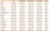
A comparison of the 2D-LCR and the 3 different types of CBCTs revealed statistically significant differences in the 7 angular and 5 linear measurements. Of these 12 measurements, none of the pairwise multiple comparisons showed a statistically significant difference for 6 parameters (ANB, AB to FH, IMPA, FMA, Co-Gn, Go-Me). LCR was significantly different from each type of CBCT in the 3 angular (SN to FH, interincisal angle, FMIA) and 2 linear (S-Go, Co-ANS) measurements. S-N was not significantly different in each pairwise comparison, except for that between CBCT methods 2 and 3. However, the disparity between the mean values in all items was within the range of clinical measurement error (Table 2).
DISCUSSION
CBCT is a useful diagnostic tool that provides considerable information to clinicians. Compared to conventional CT, in CBCT, the level of radiation is lower. Moreover, designating a measuring-point using the MPR view guarantees higher reproducibility, reliability,10 and accuracy89 of the length measurements than conventional LCR.
Considerable efforts have been made to substitute conventional LCR by means of a 2D image synthesized from a software image after CBCT. Indeed, Kumar et al.11 reported that a cephalogram synthesized in CBCT could substitute for conventional LCR. In particular, the orthogonal projection was excellent. In addition, Kumar et al.14 reported that additional LCR would not be required if a CBCT synthesized cephalogram was used. This method, however, has disadvantages in that it has low resolution than LCR, because it needs to be analyzed after the 3D data of CBCT has been converted to 2D data, and that it is impossible to designate a measuring-point in the MPR view, unlike with CBCT.
Other studies compared the measurement values of the 3D cephalometric analysis of CBCT and 2D cephalometric analysis, without converting the 3D images to 2D. Nalçaci et al.17 reported that there was no statistically significant difference in 12 of 14 angular measurements between the 2D and 3D methods. Gribel et al.19 reported that none of the angle and length values measured in CBCT were significantly different if a certain algorithm based on a trigonometric principle was applied. Unlike the aforementioned studies, the present study showed that only 6 of 12 measurements were not significantly different between the 2D and 3D analyses. The large sample size of this study may partially have accounted for the discrepancies in the findings of this and previous studies. Nalçaci et al.17 and Gribel et al.19 used a smaller sample size of 10 and 13, respectively, than that used in this study, and statistical power increases with increased sample size. The difference in the algorithm used to correct magnification of LCR may be another reason of the different results.
Damstra et al.22 used a point where a line joining the right and left measuring-point met the midsagittal plane for measuring, instead of using only one point among the bilateral measuring-point sets in CBCT. However, they did not consider the CBCT image reorientation that determined the midsagittal plane.
This study used a method in which all CBCT measuring-points were projected onto the midsagittal plane and analyzed. The one measuring-point commonly used in general orthodontic analysis was selected, and the measuring-points that appeared to overlap in LCR were excluded,23 as a designation is impossible in CBCT. The midsagittal plane was set using 3 different reorientation methods. In the case of pitch, the midpoint between the left and right Po and the midpoint between the left and right or were used to mimic LCR conditions. The CBCT measurements using these 3 types of reorientations were then compared with LCR measurements (Table 2).
When the measurements of CBCT and those of LCR were compared, there were significant differences in 7 angle values, i.e., ANB, SN to FH, AB to FH, the interincisal angle, IMPA, FMIA, and FMA, as well as in 5 length values, i.e., Co-Gn, S-Go, Co-ANS, Go-Me, and S-N. In previous studies of conventional LCR, the error range was large when setting the measuring-points because overlap occurred at bilateral measuring-points, such as the condylion, porion, and gonion.24 Stabrun and Danielsen25 reported that a periapical region was unclear in 75% of LCR, and Dibbets and Nolte26 also reported that it was difficult to identify the structures accurately in the incisal edge of the central and lateral incisors and in the apical region of the root. Although there was a significant difference in the measurement values of CBCT analysis and those of LCR in this study, the difference in the mean values of all parameters was less than ± 1 mm and less than ± 1°. In many studies, ± 2 mm or ± 2° is used as a potential threshold for clinically meaningful differences.1427 Therefore, the differences found in our results fall within the clinically acceptable range of measurement error.
CBCT is a useful diagnostic tool with many advantages and its frequency of use has been increasing gradually in clinical orthodontics in recent years. CBCT is likely to replace LCR completely as the field progresses. On the other hand, the 2D normative reference value of LCR is an important standard in diagnosis. CBCT cephalometric analysis using the midsagittal plane has advantages in that it is possible to designate a precise measurement-point using the MPR view, and it can be analyzed without additional programs. In addition, our results showed that CBCT cephalometric analysis could replace LCR because there was no clinically significant difference in either the angle or length measurements, regardless of the reorientation method used, when comparing the results of this study with those of conventional LCR. Nevertheless, it should be investigated whether is possible to use the 2D normative reference value in soft tissue analysis, as this study was limited to hard tissue analysis.
In this study, patients with facial deformity, such as cleft lip and palate, and a Menton deviation greater than 2 mm, were excluded to reduce the errors of 2D-LCR tracing, which is a limitation of this study.
CONCLUSION
No clinically significant difference was observed between CBCT analysis using the midsagittal plane and conventional LCR analysis, regardless of the reorientation methods applied to each CBCT analysis.
These results suggest that CBCT analysis using the midsagittal plane is a useful method that allows the use of 2D LCR normative values in hard tissue analysis.


 XML Download