

 PDF
PDF ePub
ePub Citation
 Print
Print


INTRODUCTION
Monocortical miniscrew-type temporary anchorage devices have been widely used to move a single tooth or segments of teeth.1,2 In addition, some studies have proposed simultaneous distalization of the entire dentition by applying force vector(s) from interradicular miniscrews to the main archwire.3 The underlying concept is that a distalizing force applied to the anterior segment might be transmitted to the posterior segment along the continuous archwire and proximal contact points, leading to distalization of the molars as well as the incisors. These reports are encouraging in terms of the efficiency of correcting a Class II relation showing Class II molars and canines and an increased overjet, in contrast to extraoral appliances or intermaxillary elastics which require patient compliance, or intraoral distalizers which cause forward movement of the anterior segment.4
Since an elastic chain connecting the miniscrew head and the archwire hook delivers a relatively constant single line of force, it is conceivable that the initial force system may be a strong determinant of the resultant displacement of the target segment. Previous studies have mainly focused on control of the anterior segment in cases of bicuspid extraction,5,6 as if respective anterior and posterior segments were independent. Along a continuous archwire tied to a non-extraction model, however, displacement of the anterior segment may affect the placement of the posterior segment due to the rigid connection between the segments. It is known that the resultant displacement pattern of an object is a function of the relationship between the center of resistance and the line of force. However, to date little is known about the effect of varying force vectors on the displacement of overall dentition, specifically with regard to the anteroposterior and vertical displacement of each segment. For instance, it is not yet clear whether a single force vector applied to the anterior segment would induce translation or rotation of the posterior segment. In addition to the clinical evidence, experimental investigation of the displacement pattern in response to force vectors with varying angulations would clarify aspects of simultaneous total arch movement.
The experimental methods that have been utilized for the interpretation of force systems and the resultant displacement patterns include the photoelasticity method,7 laser holography method,8 electrical resistance straingauge method,9 and finite element method (FEM).10 The FEM is a powerful tool, as it enables quantitative visualization of an object in three dimensions. It also allows simple and objective manipulation of geometrical configurations, material properties, loading conditions, and boundary conditions. In order to observe the differential movement pattern within the maxillary arch, three-dimensional modeling is crucial.
The purpose of this study was to investigate the stress distribution and displacement pattern of the entire maxillary arch, with regard to various distalizing force vectors applied by interdental miniscrews, to assess the possibility and predictability of movement of the entire arch.
MATERIALS AND METHODS
Model creation and boundary conditions
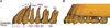
A finite element model was constructed via laser scanning of a maxillary dentition from a Nissin dental model (Nissin Dental Products, Kyoto, Japan), according to the average teeth dimensions of Asian adults with normal occlusion.11 The constructed teeth were aligned and leveled using a broad arch form (Ormco, Glendora, CA, USA) as a template, while referring to the Andrews12 prescription for inclination and angulation. The thickness of the periodontal ligament was assumed to be uniform (0.25 mm),13 and the alveolar bone crest was constructed to follow the curvature of the cementoenamel junction (CEJ) 1 mm apical to the CEJ (Figure 1).14
The dimensions of Micro-arch brackets (Tomy, Tokyo, Japan) were simulated as attachments to the teeth. The interface between the teeth and the bracket was completely joined, to omit the intervention of the composite bonding material. The distance from the incisal edge of the maxillary central incisor to the bracket slot was 4.5 mm (perpendicular to the occlusal plane), 11 mm to the labial CEJ, and 11.8 mm to the labial alveolar crest. The main archwire was modeled according to the dimensions of a 0.017 × 0.025-inch (in) stainless steel archwire, and it was assumed that there was no play between the brackets and the archwire. At the interfacial nodes between the archwire and the brackets, translational degrees of freedom along the axial direction of the archwire were not constrained, to simulate free sliding of the archwire.15 The retraction hook was modeled using a rigid (0.036-in) stainless steel wire, in order to reduce the deflection when retraction force was applied. The midpoints of incisal edges, buccal cusp tips, and root apices were used as landmarks for the assessment of displacement, and the occlusal plane was defined by connecting the midpoint of the central incisal edge and the mesiobuccal cusp of the first molar (Figure 1A). The miniscrew position was set at 8 mm apical to the archwire, at the midpoint between adjacent brackets (Figure 1B).
The teeth, alveolar bone, brackets, periodontal ligament, and archwire were all constructed using fine tetrahedron solid elements, and were all assumed to be isoparametric and homogeneous linear elastic bodies. Altogether, the model was constructed with 53,665 nodes and 272,118 elements. Due to the large number of elements, teeth and bone were approximated as uniform structures, without differentiation into enamel/dentin or cortical/trabecular bone respectively.16 Each tooth contacted the adjacent tooth at the contact point as an individual element. At the interface between the archwire and the brackets, transitional degrees of freedom were not constrained and the friction in the interface was ignored.15 Other flexural directions of the archwire were coupled at the connected nodes at the junction, to eliminate possible bracket-wire play. The Young's modulus and Poisson's ratio of the elements were obtained from previous studies (Table 1).15,17 In view of the displacement of the dentition within the basal bone, the model was constrained at the nasal floor side of the alveolar bone in all directions.
Simulation of force vectors
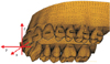
In order to investigate the influence of the height of the retraction hook on the displacement pattern and stress distribution, a retraction hook was located between the maxillary lateral incisor and canine. A single force vector (200 g) was applied by a miniscrew positioned between the maxillary second premolar and first molar to retraction hooks extending 0, 2, 4, 6, 8, and 10 mm apical to the archwire (Figure 2A). The influence of antero-posterior positioning of the retraction hook was then examined. The length of the hook was set at 0 mm, and a single postero-superior force (200 g) was applied from the same miniscrew position to each interbracket retraction hook, resulting in increasingly vertical angulations (Figure 2B).
A standard coordinate system was constructed with the x-axis corresponding to the bucco-palatal direction, the y-axis the antero-posterior direction, and the z-axis the superior-inferior direction. A +x value was defined as the medial direction, +y as the anterior direction, and +z as the apical direction (Figure 3). The displacements of the teeth were calculated by applying the x, y, and z coordinates at the midpoints of the incisal edges of the central and lateral incisors, the cusp tip of the canine, the buccal cusp tips of the premolars, the mesiobuccal cusp tips of the molars, and the root apices of each tooth. The changes in teeth axes were calculated in each plane of space. Furthermore, the von Mises stress distribution along the periodontal ligament was calculated and visualized in the contour plot, as σH = (σ1 + σ2 + σ3)/3, where σ represents the principal stresses in each dimension. Universal finite element software (Ansys version 11; Ansys Inc., Canonsburg, PA, USA) was used to calculate and visualize the results.
RESULTS
The effects of distalizing force application to variable lengths of lever arm
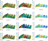
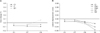
When a posterior single force (200 g) was applied to the retraction hook between the lateral incisor and canine, initial displacement of the teeth mainly occurred in the anterior segment. Distalizing force was also expressed in the posterior segment, albeit a small amount, resulting in mild distal tipping of the molars (Figures 4 and 5A). The von Mises stress was highly concentrated on the anterior teeth, especially at the lateral incisor and canine close to the retraction hook. The stress decreased in the posterior segment and showed relatively uniform distribution over the entirety of the root surfaces (Figure 5C).
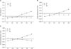
Applying force to lower level retraction hooks (conditions 1 and 2) led to greater lingual and coronal displacement of the incisal edges of anterior teeth than was apparent in the rest of the conditions, due to lingual rotation of the incisors. Bodily movement of the anterior teeth was likely to occur when force was applied to 4 mm or 6 mm retraction hooks (conditions 3 and 4). When force was applied to higher level hooks that extended more apically, lingual root movement and labial crown movement of the anterior teeth occurred, as well as intrusion of the anterior teeth and extrusion of the posterior segment, resulting in a flattening rotation of the occlusal plane (conditions 5 and 6). The rotational and vertical changes were greater in the anterior segment according to the change of vector angulation, in contrast to the constant distalization in the posterior segment evident in all conditions (Figures 4 and 5). The amount of molar distalization increased slightly as the length of the lever arm increased, due to the greater horizontal vector of the distalizing force (Figure 4B).
The effect of distalizing force application on the main archwire with variable points of force application
As the retraction hook point moved posteriorly (conditions 7 and 8), lingual inclination of the anterior teeth became more pronounced. The molars, in contrast, showed less distal tipping and even slight mesial tipping in condition 8, due to the elastic bowing of the archwire between the second premolar and first molar (Figure 6A).
When viewed from the front, greater vertical angulation of the vector induced more buccal tipping in all teeth, possibly due to the increased vertical component of the force on the buccal side (Figure 6B), leading to broadening of the arch form. Broadening of the arch was a uniform finding in conditions 1, 7, 8, and 9 possibly due to the mere buccal component of force created by the miniscrew positioned on the buccal side (Figure 6B). Within the boundary of this study, minimal buccal displacement was found when the hook was positioned distal to the canine (condition 7), indicating effective distalization with minimal buccal tipping of the posterior segment.
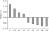
Rotation of the occlusal plane according to the line of action of the distalizing force
Figure 7 shows the rotation of the occlusal plane in conditions 1 to 9, presented in descending order of the degree of rotation. Condition 6 elicited the most pronounced flattening of the occlusal plane. As the lever arm shortened, the amount of rotation became smaller, resulting in conversion of the direction of rotation between conditions 2 and 3. As the point of force application moved posteriorly, the occlusal plane became steeper (Figure 7).
DISCUSSION
Unlike predicting the movement of a single unencumbered tooth or a segment of teeth, it is difficult to predict the movement of an individual tooth tied to a continuous archwire, because inherently the system is a large segment, which has been characterized as being statically indeterminate.18 Therefore, instead of mathematical calculations, the type of modeling described herein may predict the resultant displacement patterns more accurately, thus providing better clinical guidelines for the manipulation of the entire dental arch. As the finite element model in this study involved multiple interfaces between each material, i.e., tooth, bone, periodontal ligament, bracket, and wire, the material properties and each interface were approximated according to previous reports, to simulate the clinical situation within the practical limitations of the experiment. Cattaneo et al.19 claimed that load transfer did not differ between homogenous and density-based alveolar bone. Since the present study focused more on the overall displacement pattern of a large segment, rather than the specific stress distribution in a small area, a homogenous model was considered appropriate. The material properties of the periodontal ligament have historically been rather controversial, with the elastic modulus ranging from 0.01 MPa to 100 MPa.17,20,21 While some insist on the non-linearity of its elastic modulus,16 it has been shown that the non-linearity mainly affects the magnitude of the stress, and not the actual movement pattern of the teeth.19 Using an iterative calculation method, Andersen et al.22 claimed that the material properties did not significantly reverse the resulting displacement pattern. Since the effect of the force system is exerted by direct contact with juxtaposed elastic materials, any voids or plays were not defined at each interface between the bracket and wire, or between the bracket and tooth.15 Although it was anticipated that archwire deformation would cause flexure of the long teeth segment, an archwire with indefinite strength was considered unrealistic,23 so the archwire in the present study was defined as an elastic material.
In the present model, the point of force application in the alveolus was set 8 mm from the archwire, after considering the average crown height and the level of the mucogingival junction in healthy subjects.24,25 The displacement pattern of the dentition was analyzed when 200 g of distalizing force was applied at varying points of force application along the archwire.
When the distalizing force was applied to the retraction hook between the lateral incisor and canine at various heights, stress and the initial displacement of the teeth were found mainly around the anterior segment. However, the stress also spread to the second molar, leading to its posterior movement and distal tipping. This finding may be valid evidence in support of the assumption that when distalizing force is applied to an anteriorly located hook, movement of the total arch is effectively induced.
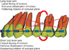
When force was applied to lower level hooks, initial displacement of the anterior segment led to lingual inclination and downward displacement of the incisal edges, as well as intrusion of the posterior segment, including the premolars and molars, which resulted in steepening of the occlusal plane. In contrast, when force was applied to higher level hooks, lingual root movement and labial crown movement of the anterior teeth and extrusion of the posterior segment occurred, resulting in flattening of the occlusal plane. Although these occlusal plane rotations were somewhat exaggerated by the wire deflection in the anterior segment, they can be explained by changes in the relationship between the center of resistance of the entire dentition and the line of action. Jeong et al.23 reported that the center of resistance of the full maxillary dentition was 11.0 mm apical to and 26.5 mm posterior to the incisal edge of the upper central incisor when using the same finite element model employed in this study. Thus, the force applied to lower level retraction hooks has a line of action that passes below the center of the resistance that causes a steepening rotation of the occlusal plane, and vice versa for forces applied to higher-level retraction hooks. These findings are not concordant with those of Billiet et al.,8 who reported that translation of the maxillary dentition was observed when the force vector applied by the head-gear passed through the area of the key-ridge. This is because they applied extraoral force from outside the maxillary complex, while the distalizing force in this study was from miniscrews placed within the maxillary complex, resulting in the displacement of maxillary dentition relative to the maxilla, with the periodontal ligament as an interface. Thus, the results of this study appear to be more applicable to the clinical situation using miniscrews,26 and the displacement pattern of the entire arch may be a function of the relationship between the line of action and the center of resistance of the maxillary dentition, which can be applied to arbitrary movement of the entire arch (Figure 8).
The lingual root movement of the anterior teeth when force is applied to higher-level hooks can also be explained by the line of action passing above the center of resistance of the anterior teeth. However, deflection of the wire may also affect displacement, exaggerating the labial lifting of the incisors.5 Therefore, a long retraction hook can be effectively applied in cases that call for lingual root movement of the anterior teeth, while being cautious of extrusion of the posterior segment. Deflection of the archwire can be minimized by loading the orthodontic force periodically to provide sufficient time for rebounding of the archwire, or by using a more rigid archwire.
In contrast to the significant conversion in the displacement pattern of the anterior segment associated with the length of the retraction hook, the posterior segment showed relatively consistent and mild displacement in the distal direction. This result is encouraging, as conventional intraoral distalizers have shown a tendency to cause significant distal tipping of the molars.4 Choy et al.27 suggested that the s2 (variance of distribution of stress) value increased with blunting of the root, and that a tooth with a large s2 value might be less prone to tipping, as the axis of rotation is more manageable. Applying this concept, the posterior segment can be described as a long object antero-posteriorly, relative to the line of action, presumably with a larger s2 value and greater resistance to tipping than the anterior segment, which can be described as a short object antero-posteriorly. Therefore, highly accurate appliance design, such as lever arm design, is more important for control of the anterior segment than the posterior segment. A relatively uniform distalization pattern, regardless of the level of the line of action, encourages distalization of the molars using a continuous archwire, suggesting a fail-safe distalization system.
When postero-superior distalizing force was applied to the main archwire, the vertical component of the force, which increased as the retraction hook was located more posteriorly, led to intrusion and buccal tipping of the molars. This finding is reasonable, since the force was applied to buccal surfaces of the teeth, which generated a moment of force tipping them buccally. The moment of force increased with the increase in vertical force vector. This can be clinically relevant when an intrusive force is applied from a miniscrew placed in buccal interdental alveolar bone to treat an anterior open bite, as buccal tipping of the molars can cause extrusion of the palatal cusps, which in turn might worsen the open bite.28,29 However, a single distalizing force on the buccal side may not have to be balanced by another force on the lingual side, as long as the vertical component of force remains minimal.3 The buccal component (x-axis) of force also partially contributed to the buccal tipping tendency, especially when the retraction hook was located between the lateral incisor and canine. Schematic guidelines taking these findings into consideration are proposed in Figure 8, in terms of distalization and/or intrusion of the entire maxillary arch. These may still be theoretical, but there have already been substantial clinical reports and studies that support them.26,30 Overall, arbitrary control of the entire maxillary dentition, encompassing rotation and translation, is expected to be feasible.
The design of this study has some limitations. Firstly, the study intended to theoretically visualize the initial displacement and stress distribution of forces during full arch distalization using a FEM, so the results may not reflect exact clinical outcomes, which are influenced by the cumulative effects of continuous bone reactions and rebounding of the archwire related to secondary displacement of the teeth. Secondly, the thickness of the periodontal ligament was assumed to be uniform (0.25 mm), whereas in reality, it has a hour-glass shape with the narrowest zone at the mid-root level.17 Furthermore, other material properties assumed in this study may differ from those found in the corresponding natural structures. For instance, the exact thicknesses of the cortical bone and trabecular bone were not incorporated into the FEM model, since they were not considered determinants of the initial displacement. Lastly, there are other factors that were not taken into consideration, such as deformation of the bone tissue and brackets, occlusal force, and soft tissue pressure from perioral muscles and gingival fibers. Nonetheless, when supplemented with clinical, cytological, and biochemical research, the findings of this study may be effectively applied to clinical situations.
CONCLUSION
1. A single distalizing force applied at the archwire level induced initial lingual inclination of the anterior segment, and slight intrusive distal tipping of the posterior segment. In contrast, applying force from a retraction hook at a higher level resulted in initial lingual root movement of the anterior segment, and extrusive distal translation of the posterior segment.
2. When a postero-superior force was applied, deflection of the archwire increased as the retraction hook was located more posteriorly, increasing the tendency for lingual inclination and extrusion of the anterior segment. Also, the vertical component of the force led to intrusion and buccal tipping of the molars.
3. The rotation of the occlusal plane was anticipated according to the relationship between the line of force and the possible center of resistance of the entire arch.


 XML Download