

 PDF
PDF ePub
ePub Citation
 Print
Print


INTRODUCTION
In general, orthognathic surgery is preceded by presurgical orthodontic treatment such as dental alignment, dental decompensation, and arch coordination to determine the prognosis, treatment plan, and safety of the surgical procedure.1,2 However, orthodontic treatment prior to orthognathic surgery has disadvantages such as discomfort in mastication for the duration of the treatment and deterioration in facial form due to dental decompensation.
To overcome the disadvantages of presurgical orthodontic treatment, recent studies have reported orthognathic surgery methods that precede orthodontic treatment or shorten its duration.3,4,5,6,7,8,9,10 In the surgeryfirst approach, dental alignment is evaluated based on a cast model set up, a surgical procedure is outlined based on the degree of movement of the maxilla and mandible, and model surgery is performed to produce a surgical wafer.3 However, the surgery-first approach has a tendency toward high error rates as it involves an extra remounting step that can increase the chance of error.11 Recently, the development of a three-dimensional (3D) rapid prototyping technique has enabled a 3D virtual setup,12 3D surgical simulation,13 and the production of a surgical wafer,14 which may reduce the chance of errors by eliminating the need for laboratory procedures such as mounting. Combining the 3D technique with the surgery-first approach is expected to result in more accurate and predictable diagnoses, treatment plans, and outcomes.
The authors report a case of skeletal Class III malocclusion. The diagnosis and treatment plan were carried out through a 3D virtual setup and 3D surgical simulation, and a surgical wafer was produced using the stereolithography technique. Thus, the surgery-first approach was incorporated into the treatment process without presurgical orthodontic treatment, and a favorable treatment outcome was eventually achieved.
Go to : 
DIAGNOSIS AND ETIOLOGY
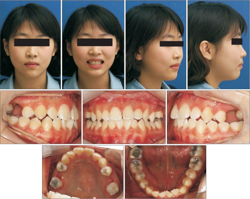
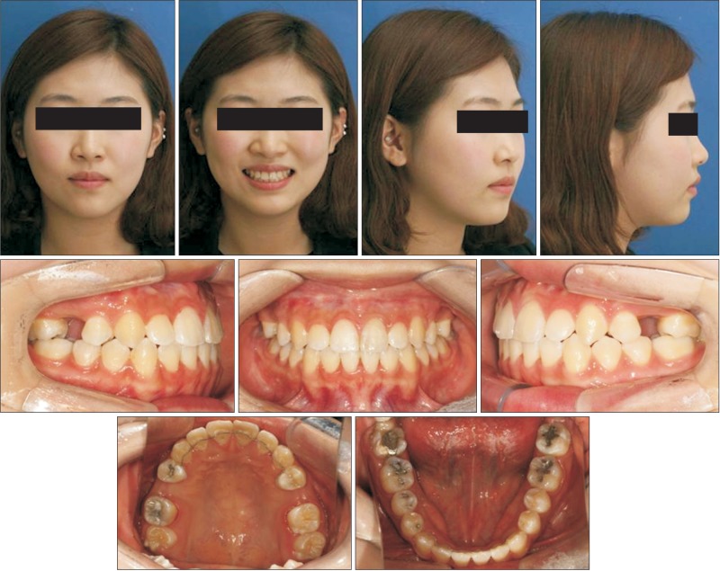
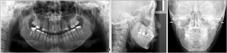
A 19-year-old woman presented to the dental clinic with anterior crossbite and mandibular prognathism. The patient had a concave profile, long face, and Angle Class III molar relationship. She had crowding and dental midline deviation (Figure 1).
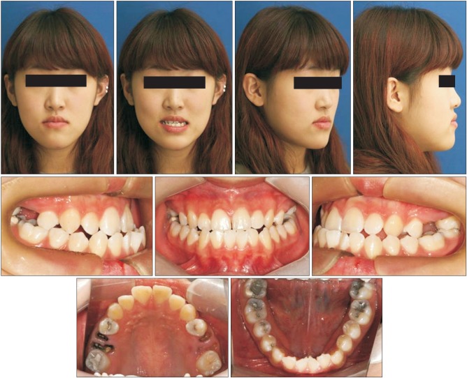
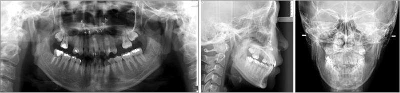
Radiological examination revealed missing left and right second premolars in the maxilla, retained root rest of the left and right first molars, and eruption of the third molar in the maxilla (Figure 2). Cephalometric analysis revealed a skeletal Class III malocclussion with minor deficiency in the maxilla; posteroanterior view revealed canting down of the maxilla to the right, and deviation of the chin toward the left side of the mandible (Table 1). However, computed tomography (CT) revealed that there was no canting of the maxilla, and the longer body length of the right side of the mandible caused the chin point deviation (Figure 3).
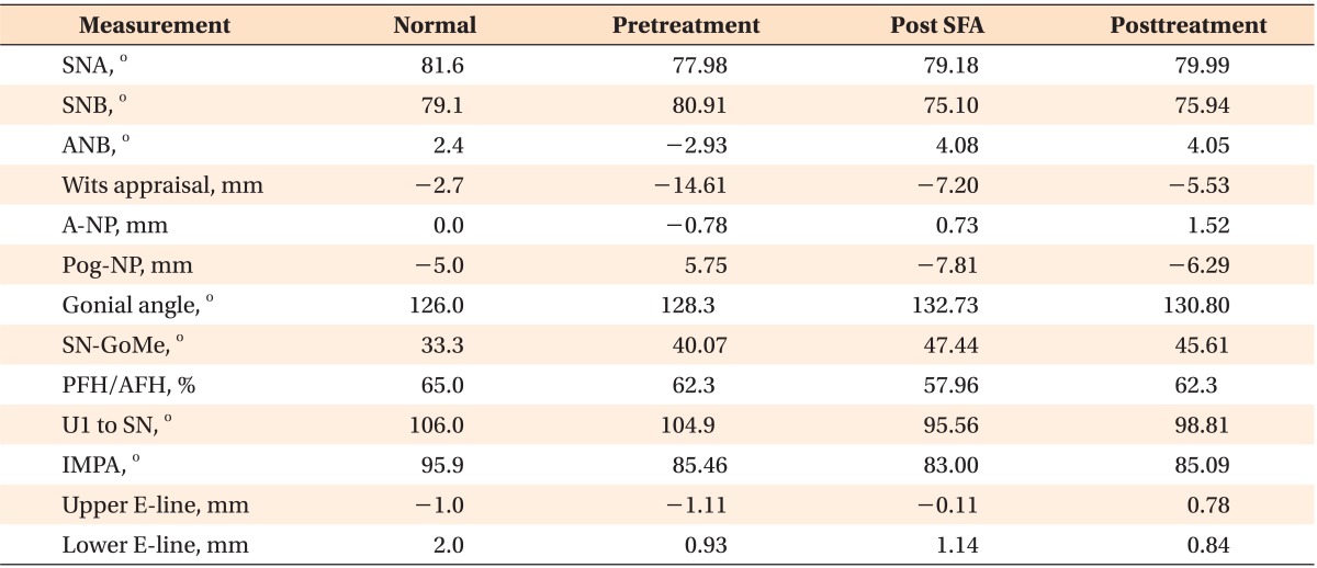

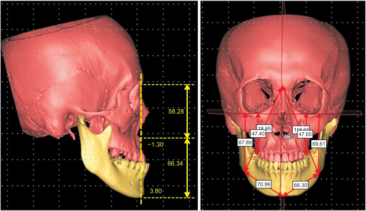
Table 1
Findings of the cephalometric analysis conducted for the patient
SFA, Surgery-first approach; SNA, sella-nasion-A point angle; SNB, sella-nasion-B point angle; ANB, A point-nasion-B point angle; A-NP, nasion perpendicular to A point; Pog-NP, nasion perpendicular to pogonion; SN-GoMe, gonion-menton line to sella-nasion line angle; PFH/AFH, posterior facial height/anterior facial height; U1 to SN, upper incisor to sella-nasion line angle; IMPA, incisor mandibular plane angle; upper E-line, upper lip to Ricketts' E-line; lower E-line, lower lip to Ricketts' E-line.
![]()
Go to :
TREATMENT OBJECTIVES
The treatment objectives were to attain a well-balanced facial form, correct the Angle Class III molar relationship and crossbite, and establish proper overjet.
Go to :
TREATMENT ALTERNATIVES
The first treatment option was orthodontic treatment with orthognathic surgery, which involves arch coordination, dental decompensation, and resolution of crowding through the conventional method of presurgical orthodontic treatment followed by postsurgical orthodontic treatment. The second treatment option was the surgery-first approach, which involves orthognathic surgery followed by postsurgical orthodontic treatment. The third treatment option was camouflage, which involves extraction of the mandibular first premolar. Camouflage would resolve the patient's chief complaint of anterior crossbite, but it would result in no improvement in facial form and worsening of the lingual inclination of the mandibular anterior teeth.
In this patient, the surgery-first approach was chosen, as the patient desired fast resolution and improvement of the facial form; in addition, occlusion was stable enough for the surgery-first approach, horizontal and vertical disharmony was low, and additional tooth extraction was not indicated.
Go to :
TREATMENT PROGRESS
3D virtual setup and surgical simulation
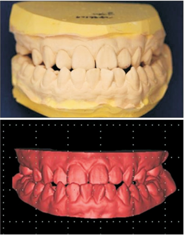
A 1-mm CT slice was converted into a 3D image using Mimics® 14.0 (Materialise, Leuven, Belgium), with separation of the maxilla and mandible. The patient's initial cast model was transformed into a 3D digital cast model (initial digital cast model) using a 3D light scanner (Rexcan DS2; Solutionix, Seoul, Korea; Figure 4). A clear dental image was obtained by removing the dentition from the 3D CT image, followed by superimposition of the initial digital cast model onto the 3D CT image (Figure 5). Then, each tooth on the digital cast model was separated using Mimics® 14.0, and the virtual setup was initiated by predicting the presurgical orthodontic treatment, which resulted in the production of the virtual setup cast model (Figure 6). Based on this model, the surgical plan was confirmed by carrying out the surgical simulation on Mimics® 14.0 (Figure 7). The virtual setup cast model was substituted into the initial digital cast model for the production of the surgical wafer, and the premature contact was resolved through mandible autorotation with the condyle axis as a reference. The surgery was processed with the intermediate and final surgical wafer, which was produced using the rapid prototyping technique.

Orthognathic surgery by the surgery-first approach
The orthognathic surgery plan for the patient was as follows: 2-jaw surgery, 2-mm total impaction, and 2-mm advancement though Le Fort I osteotomy of the maxilla, and bilateral intraoral vertical ramus osteotomy (IVRO) setback (right side 8 mm setback, left side 6 mm setback) of the mandible. The retained root rests of the first molars on both sides of the maxilla and the third molars on both sides of the mandible were extracted prior to surgery, and the surgical wire that was produced from the initial cast was directly bonded (Transbond XT®; 3M Unitek, St. Paul, MN, USA) onto the teeth.
Postoperative orthodontic treatment
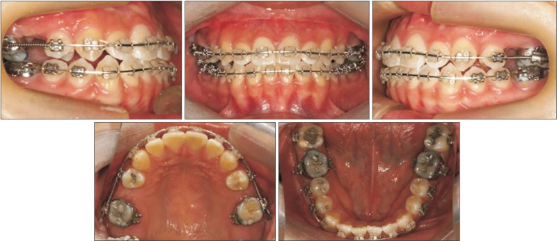
Physiotherapy was carried out at the department of oral and maxillofacial surgery for 6 weeks after the surgery. After confirmation of the recovery of concrescence and function of the maxilla and mandible, postsurgical orthodontic treatment was initiated at the department of orthodontics (Figures 8 and 9).
At the initial visit for postsurgical orthodontic treatment, the surgical wire was removed (Figure 8). The full bonding through the 0.022-inch slot of Clarity® brackets (3M Unitek, Monrovia, CA, USA) resulted in the alignment of the maxillary and mandibular dentition and decompensation of the mandibular dentition. The spaces of the second premolar and the first molar on both sides of the maxilla were maintained to provide restoration of a second premolar, and the third molar on both sides of the maxilla was substituted as the second molar.
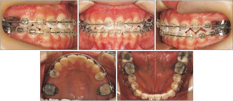
To correct the transverse discrepancy, a constriction lingual arch (0.032 × 0.032 TMA [titanium molybdenum alloy]) was applied to the mandiblular arch (Figure 10). Three months after start of treatment, 0.016 × 0.022 nickel-titanium (NiTi) wire was engaged on the upper and lower dentition, and Class III elastics were used to correct the minor Class III canine key on the right side; in addition, an open coil spring was used to regain space for the second premolar on the left side of the maxilla (Figure 11).

Six months after start of treatment, 0.019 × 0.025 NiTi wires were engaged on the upper and lower dentition, but the space for the second premolar was still not sufficient, and eruption of the third molar on the left side of the maxilla was seen (Figure 12).
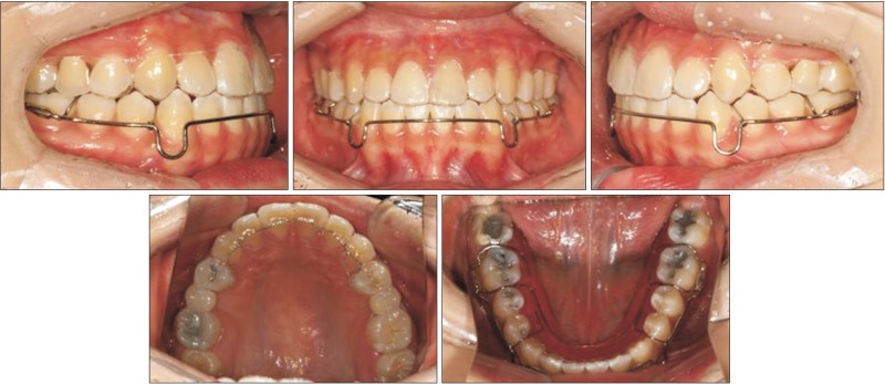
Twelve months after start of postsurgical orthodontic treatment, the space for the second maxillary premolar was appropriately formed and debonding was carried out. Since then, a clear retainer with pontic has been worn full-time to maintain the space of the second premolar of the maxilla (Figure 13). Implants are being placed at present.
Go to :
RESULTS
The treatment resulted in a symmetrical, balanced facial form and transformation of the concave profile into a mild convex profile. The concordance of the midline of the face and the midline of the dentition of both maxilla and mandible was confirmed. The substitution of the second molar for the first molar resulted in a Class I canine and molar relationship on both sides, and appropriate overjet and overbite was achieved (Figure 14).
Root parallelism was confirmed on a panoramic radiograph. When the lateral cephalometric radiographic superimposition was carried out, a greater posterior impaction was seen relative to the surgical plan; therefore, the degree of the occlusal plane and clockwise rotation of the mandible were increased, but these were still within the normal range. With the increase in the occlusal plane, the flat smile arc was changed, which led to a consonant smile arc. The disappearance of the chin point deviation was seen from the frontal view (Figure 15).
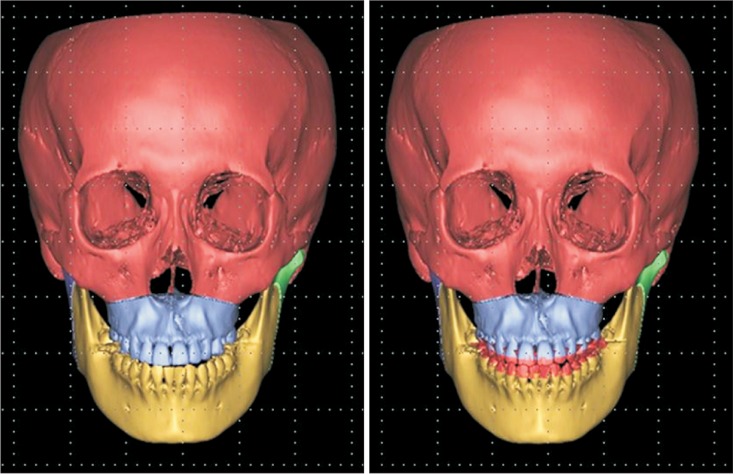
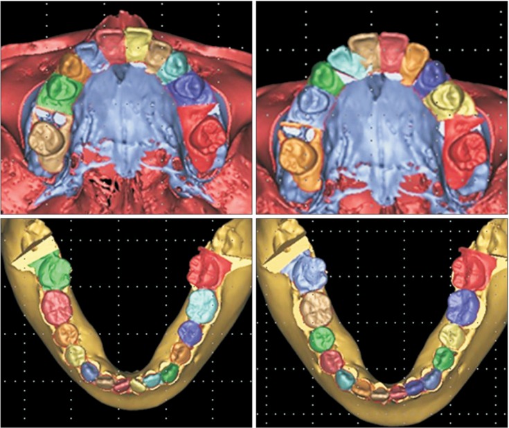
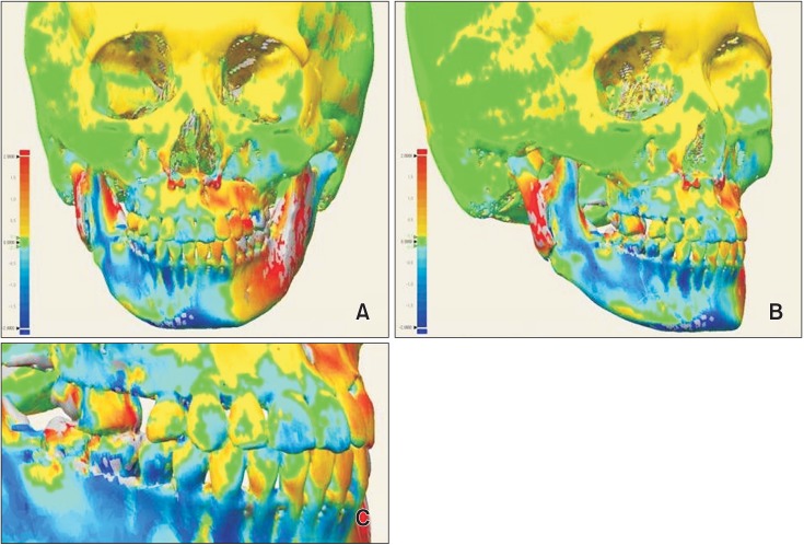
A comparison of the 3D virtual setup, surgical simulation image, and posttreatment CT image was performed by superimposition and a color-coded discrepancy map using Rapidform XOV2 software (INUS Technology, Seoul, Korea; Figure 16). Discrepancies were color-coded and evaluated in the 3D image based on the range of difference values in the simulated cast, pretreatment CT images, and posttreatment CT image.
Go to :
DISCUSSION
The patient described herein had skeletal Class III malocclusion, and the diagnosis and treatment plan were established through a 3D virtual setup and 3D surgical simulation. The surgical wafer was produced using the stereolithography technique, and the treatment was carried out using the surgery-first approach.
Recently, a number of reports regarding surgical orthodontic treatment without preoperative orthodontic treatment (i.e., the surgery-first approach) have been published.3,7,8,9,15,16
The advantages of the surgery-first approach are as follows: high patient satisfaction due to immediate improvement of facial profile at the beginning of the treatment,3,6,7,16 shorter duration of treatment3,7,15 due to rapid tooth movement,17,18,19 and the possibility of physiologic decompensation3,6,7 through facilitation of the soft tissue as a result of improvement in the maxillary and mandibular discrepancy.
However, the surgery-first approach has the following disadvantages: the inability to use presurgical occlusion as a guide, difficulty in obtaining stable occlusion after surgery,7 and need of a clinician's experience for the exact prediction of tooth movement in presurgical orthodontic treatment and the exact prediction of the approach notwithstanding structural discrepancies.3 Therefore, the surgery-first approach is mainly chosen when there are at least 3 stable occlusal contact points, a minor curve of speed and vertical problem, minor or no transverse discrepancy, and when there is no indication for extraction.3,6
To achieve predictable results in orthognathic surgery, the following factors must be considered: 1) the exact diagnosis, 2) accuracy of laboratory procedures in the model surgery and production of surgical tools, and 3) skill of the oral and maxillofacial surgeon. To reduce errors in the process of establishing the diagnosis and treatment plan, recent studies have been conducted using the 3D virtual technique.20,21
The development of computer-aided surgery has facilitated a reduction in the duration of presurgical orthodontic treatment. Kang et al.10 reported the results of orthognathic surgery with reduced duration of presurgical orthodontic treatment. After 3D analysis, the occlusion of the final surgical wafer was determined, followed by superimposition of the current occlusion status. Then, the surgery plan was finalized through 3D virtual surgery, and the entire process of making the surgical wafer was carried out on a computer. Cevidanes et al.13 reported that computer-aided surgery could make the elaboration of the surgical plan a more flexible process, increase the plan's level of detail and accuracy, yield higher operative precision and control, and enhance documentation of cases.
With the surgery-first approach, the surgical plan is finalized prior to presurgical orthodontic treatment, which requires much effort to ensure a predictable result; a set method has not been established, although various studies have reported this approach. Nagasaka et al.7 established a plan for the surgery-first approach through a cephalometric radiograph and occlusogram. Villegas et al.16 and Liou et al.6 established a surgical plan through model surgery using an initial cast model.
However, if the surgery-first approach is followed without the cast model setup, the range and degree of predictions would increase, which can lead to a reduction in accuracy. Baek et al.3 established a surgical plan that included the cast model setup process for the prediction and simulation of dentition, decompensation of the whole dentition, and arch coordination. To achieve a more accurate surgical plan in the laboratory, the patient's occlusal status is transferred to a semi-adjustable articulator. Then, the cast model setup that predicts the presurgical orthodontic treatment is initiated, and this becomes the reference for the model surgery to be carried out. Based on the confirmed surgical plan, the cast model setup is replaced by the initial preoperative cast model to produce the intermediate and final surgical wafers.
Sharifi et al.11 reported the occurrence of errors when the facebow is transferred and the cast is mounted during model planning for orthognathic surgery; the possibility for errors increases even further during substitution of the final setup cast model for the initial preoperative cast model. These errors in laboratory procedures can be overcome by using the 3D virtual technique. The possibility of errors associated with 2D diagnosis can be reduced and a more accurate diagnosis can be facilitated through 3D analysis of the recomposed 3D CT image.14,20,22
In our case, to obtain predictable results and to reduce errors during the establishment of a diagnosis and treatment plan, 3D diagnosis, 3D digital model setup, and 3D virtual surgery were used, which were facilitated by the initial patient data. For the utilization of the reconstructed CT image, the steps of facebow transfer and articular mounting to transfer the position of the maxilla and mandible to the cranial base were omitted, thereby decreasing the chance of error. The cast model setup to predict the presurgical orthodontic treatment also used 3D digital imaging,12 and Mimics® 14.0 was used for the surgical simulation. Thus, an accurate treatment plan was established.
Consequently, no errors are encountered when the initial digital cast model is replaced by the intermediate and final wafer, because the use of 3D imaging software allows several 3D objects (virtual setup cast model and initial digital cast model) to be moved equally at the same time, and 3D objects can be exchanged with each other without replacement of the initial digital cast model by the virtual setup cast model by superimposition. In other words, the initial digital cast model can be substituted by the virtual setup cast model by moving the virtual setup cast model and initial digital cast model at the same time during the surgical simulation. The intermediate and final surgical wafers can also be produced through stereolithographic technology.10,23
Using 3D models, all of the procedures for diagnosis and wafer production in the model surgery can be simulated, intermediate assessment can be conducted, and the intermediate and final surgical wafers can be produced. Therefore, errors encountered during laboratory procedures can be minimized.
The cranium in the posttreatment CT images was used as a reference for superimposition of the simulated and posttreatment data, and results were acceptable after evaluation by a color-coded discrepancy map.
The only possibility for error would arise during the superimposition of the scanned initial digital cast model to the dentition of CT image. On the CT image, it is difficult to obtain the precise image because of artifacts on the dentition; therefore, an error can occur because of an unclear reference when the 3D digital cast model, which is transformed from the patient's initial cast model through the optical scanner, is superimposed onto the CT image.
Go to :
CONCLUSION
In the surgery-first approach, which increases patient satisfaction due to fast improvement of facial profile and aims for physiological movement of teeth, the dental cast set up and surgery simulation using a 3D technique can help orthodontists and oral surgeons to establish an accurate diagnosis and treatment plan and to obtain predictable results.
Go to :
 XML Download