

 PDF
PDF ePub
ePub Citation
 Print
Print


INTRODUCTION
Soft tissue pressure is a factor that influences craniofacial growth and development patterns.1,2 Further, prior reports have indicated that a correlation exists between tongue position and malocclusion.3,4 A low tongue posture or tongue-thrusting habit can produce an anterior open-bite and mandibular prognathism. Moreover, abnormal tongue position and functioning are reported to cause relapses after treatment for anterior open-bite, and are potential risk factors for long-term stability.5,6
A relapse of anterior open-bite during the retention period is common, and clinicians often face the challenge of retaining treatment results, or retreating a relapsed open-bite. To date, various retention protocols have been suggested for preventing relapses caused by low tongue posture and tongue-tie. Reports have indicated the success of the tongue crib appliance in treating an anterior open-bite malocclusion in young patients with a tongue thrusting habit.7,8,9 Likewise, tongue reduction has been effective in preserving treatment results in patients with macroglossia.10,11,12 Orofacial myofunctional therapy has also been effective in maintaining closure of anterior open-bite malocclusions that result from changes in tongue position and functioning patterns.13,14 Conversely, no consensus exists regarding the indications, timing, or method of surgical repair of tongue-tie anomalies.3,15,16,17,18 A lingual frenectomy is usually recommended in cases of tongue-tie, but surgical intervention is not always justified, especially in cases in which the patient has no specific complaints of discomfort.18
Herein, we present findings from the 10-year follow-up of a patient who was retreated for a relapsed anterior open-bite without surgical intervention. Treatment of the patient with molar intrusion using temporary skeletal anchorage was initially successful, but the anterior open-bite reoccurred during the retention period due to a persistent low tongue posture. A tongue elevator was subsequently applied as an active retreatment alternative, and was used thereafter as a retainer. The result was successful bite closure and long-term stability. Accordingly, the purpose of this report is to suggest the use of a tongue elevator as a treatment or retention alternative for anterior open-bite.
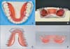
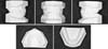
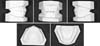
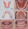
A tongue elevator is a removable appliance comprising an acrylic base, occlusal rests, and several retentive elements (Figure 1). The acrylic base occupies the entire sublingual space, except for the lingual frenum, and the occlusal rests are placed in the lingual occlusal grooves of the posterior teeth. For retention, a labial bow and other retentive clasps can be added.
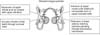
The function of the tongue elevator is to keep the tongue in a higher than usual position, which is accomplished by the sheer volume of the acrylic base. The positional change induced by the tongue elevator brings about three dentoalveolar effects (Figure 2).19,20 First, the tongue tends to go back to its original position when elevated, which generates a downward force. This force is then transmitted to the occlusal rests of the appliance, which results in intrusion of the lower posterior teeth. Second, when elevated, the tongue occupies the space under the palatal vault, and contacts the upper dentition. In this position, the tongue exerts an outward force that results in upper arch expansion. Finally, the pushing force exerted by the elevated tongue can be used in conjunction with a transpalatal arch, or upper removable retainer with occlusal rests, to intrude the upper posterior teeth. Thus, the anterior open-bite can be corrected by inhibition of posterior alveolar growth.
The tongue elevator was first described by Chung19 as a mechanism to correct cases of low tongue posture with anterior open-bite. Subsequently, the effectiveness of the tongue elevator was reported by Kim et al.,20 who demonstrated the improvement of open-bite in patients with low tongue posture.
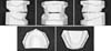
The amount of tongue elevation required for each treatment is determined by clinician experience. In cases of tongue-tie, the volume and height of the resin component of the appliance should be reduced, because excessive tension is generated in these patients compared to normal patients with an equal degree of tongue elevation (Figure 1C and 1D). The modified form of the appliance, when used in patients with tongue-tie, produces the appropriate amount of tongue elevation and tension, and results in comfort to the patient.
After wearing the appliance in the lower arch, the patient was asked to perform tongue movements in all directions. He was instructed to swallow with the upper and lower teeth occluded, and the lips in contact. As well, the application of thumb pressure under the chin proved helpful. This exercise was integral in achieving the proper effects of the appliance, and in avoiding any undesirable iatrogenic tongue thrust.
DIAGNOSIS AND ETIOLOGY
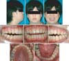
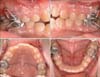
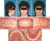
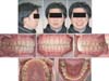
A 19-year-old male patient presented with the chief complaint of difficulty in chewing his food. Clinical examination revealed a retrusive chin, incompetent lips, open-bite, Class III molar relationship, and a negative anterior overbite with shallow overjet (Figures 3 and 4). A minimal amount of crowding was observed and, although the tongue was normal in size, it was positioned low and had tongue-tie (Figures 3 to 5). The patient did not complain of any discomfort or difficulty in function or pronunciation. Lateral cephalometric analysis revealed a Class II skeletal relationship and hyperdivergent pattern (ANB = 5.9°, FMA = 31°; Table 1 and Figure 5A). No indications or symptoms of respiratory disturbances were apparent, and there were no pathologic findings in the temporomandibular joint area.
TREATMENT OBJECTIVES
The treatment goals were to (1) correct the open-bite, (2) improve facial esthetics, and (3) improve the tongue posture for stability.
TREATMENT ALTERNATIVES
Depending on the individual causative factors, various approaches including orthodontic extrusion of anterior teeth, intrusion of posterior teeth, and a combination of orthodontic and orthognathic surgeries can be used to treat anterior open-bite. Orthodontic extrusion of anterior teeth may reduce anterior open-bite; however, it does not cause any skeletal changes. Conversely, the other treatment options are known to induce skeletal effects. Intrusion of posterior teeth, as well as surgical impaction of the posterior maxilla, can result in a counterclockwise rotation of the mandible, closure of the anterior open-bite, and forward and upward displacement of B-point and pogonion. Additionally, the results may improve a retrognathic profile to a Class I skeletal relationship. The difference between the two options is dependent on the dental or skeletal causative factor, the amount of vertical correction, and the risks of the surgical procedure. To attain long-term stability, however, a lingual frenectomy and tongue exercises are also required to minimize the risk factors for relapse.
After discussing the various treatment options and the importance of correct tongue posture, the patient opted to receive only orthodontic treatment, without any surgical procedure. In order to correct the anterior open-bite, plans were made to intrude the upper and lower posterior teeth with the aid of temporary skeletal anchorage. The patient opted not to have a lingual frenectomy, as he felt no tongue discomfort. Instead, he promised to comply with the tongue exercises, acknowledging the potential for relapse if the exercises were not performed.
TREATMENT PROGRESS
Four C-tube plates (Jin Biomed Co., Bucheon, Korea) were installed with mini-screws (4 mm in length and 1.5 mm in diameter, Jin Biomed Co.), at the zygomatic buttress in the maxilla and the mandibular posterior buccal cortical bone between the first molar and second molar (Figure 6). A transpalatal arch and lingual arch were incorporated in the upper and lower dentition, respectively, to maintain the torque of the first molar and the intermolar width. The patient was reminded of the importance of tongue position during treatment, and was instructed to swallow in a manner that forced the tongue to contact the palatal surface. After four months, during which time contact of the opposing premolars was established, the fixed orthodontic appliance was combined with further molar intrusion and Class III elastics, to achieve an appropriate overbite and overjet, as well as better interdigitation.
RESULTS
Treatment results and relapse after 3-year follow-up
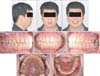
A class I molar and canine relationship, and a positive overbite were obtained over an 11-month treatment course using the described technique (Figures 5B, 7, and 8). The treatment also resulted in good periodontal health with minimal root resorption. The total amount of intrusion for the upper first molar was 1.1 mm, and 0.9 mm for the lower first molar (Table 1 and Figure 9A), while the overbite improved from -4 mm to 1.5 mm. As a result, the mandible rotated counterclockwise (FMA = 31° vs. 28°, respectively), and the B point and pogonion moved forward (SNB = 78° vs. 79.5°; Pog to N-perp = -11.5 mm vs. -9 mm; Table 1). Collectively, the results contributed to an improvement in lip competency and facial profile.
The patient regularly performed the prescribed tongue exercises. During treatment, the tongue posture was maintained in a normal position of contact with the palatal surface, and seemed to adapt to the post-orthodontic intraoral conditions. Upper and lower wrap-around removable retainers, as well as a lower anterior lingual fixed retainer, were used. The patient was advised to chew his food thoroughly, and to exercise his tongue to ensure contact with the palatal surface.
Nevertheless, after a 3-year retention period, the patient exhibited an anterior open-bite relapse (Figure 10). Lateral cephalograms revealed a relapse of the intruded posterior molars (U6-PP = 26.5 mm vs. 27.4 mm; L6-MP = 33.6 mm vs. 34.4 mm, respectively; Table 1 and Figures 9B, 10, 11), and clockwise rotation of the mandible (FMA = 28° vs. 29.5°, respectively). Moreover, the tongue had moved to a lower position (mean tongue-to-palate distance = 3.4 mm vs. 8.9 mm, respectively), which was not observed during treatment or the early retention period, and may have been a primary cause of the anterior open-bite relapse.
Retreatment using a tongue elevator
The patient declined to repeat the entire treatment protocol with the full fixed appliance, because of the associated discomfort, cost, and time. Likewise, the patient remained unwilling to undergo a lingual frenectomy, despite the low tongue posture. Therefore, a minimally invasive treatment approach involving the use of a tongue elevator was selected to retreat the relapsed anterior open-bite and low tongue posture. This appliance eliminated the risk factors related to low tongue posture, and instead utilized the tongue force to prevent relapse of the intruded molars.
A tongue elevator modified for tongue-tie was used in the lower dentition. A wrap-around retainer with occlusal rests and a reduced resin plate that allowed adequate vertical support of the maxillary molars and maintained room for the elevated tongue was used in the upper dentition (Figure 12). To correct the rotated upper right incisor, a spring was added. An exercise protocol was communicated, and the patient was reminded of the proper tongue position at rest. The appliances were worn for 24 hours a day for three months, and the overbite improved. Afterwards, the appliance was worn only at night. Using the modified retainers, the tongue shifted to an upward position and, even after four years, the overbite was retained in the corrected position (Figure 13). The upper and lower molars were intruded by 0.7 mm and 0.8 mm, respectively (Table 1 and Figure 9C), the mandible was rotated counterclockwise, and the anterior open-bite was closed (FMA = 29.5° vs. 28.7°; overbite= -1 mm vs. 0.5 mm; Table 1 and Figure 9C). The improved conditions were subsequently retained for six years following the use of the tongue elevator (Figures 9D, 14, and 15).
DISCUSSION
Depending on the individual causative factors, various orthodontic treatment modalities such as orthodontic extrusion of anterior teeth, intrusion of posterior teeth, and a combination of orthodontic treatment and orthognathic surgery can be used to correct anterior open-bite. However, prior studies have reported that only 75% of surgical or non-surgical anterior open-bite treatments have exhibited long-term success.22,23,24
Intrusion of posterior teeth has an effect similar to posterior impaction of the maxilla. Specifically, both conditions tend to result in the rotation of the mandible counterclockwise, thereby resulting in closure of the anterior open-bite, as well as forward and upward displacement of B-point and pogonion. These changes allow Class II skeletal malocclusions with associated open-bite to be corrected to a Class I relationship without surgical intervention.25,26,27 Despite successful treatment results with molar intrusion, relapse has been reported in long-term studies. Sugawara et al.26 reported that intrusion of mandibular molars using miniplates resulted in relapse within the first year in approximately 30% of cases. Similarly, Baek et al.27 reported that a significant number of relapses occurred in maxillary molars intruded with miniscrews within three years of retention, with over 80% of the total relapses occurring in the first year.
Soft tissue pressure, in particular the pressure that results from tongue position and function, has been reported to affect anterior open-bite, and could pose a potential risk for long-term stability of treatment results.5,6 Although previous studies have investigated the effects of tongue posture and function,28,29 clinical examination of the tongue is both limited and subjective, due to its muscular nature and surrounding anatomic structures. Moreover, there is no universally accepted classification system or randomized controlled trial.3,15,16,17,18
In this particular case, superimpositions of lateral cephalograms indicated that the relapse of the anterior open-bite could be attributed to molar extrusion and a low tongue posture (Figure 9). During the active treatment and early retention periods, tongue exercises alone seemed to be effective in altering the tongue posture. However, at the 3-year retention, the tongue posture moved to a lower position. The shift in tongue posture may have caused the extrusion of the intruded molars, which in turn may have been affected by the tongue-tie.
Surgical and non-surgical approaches are available for treatment of tongue-tie. However, a generally accepted classification system or treatment strategy has not been established for surgical intervention of tongue-tie,3,15,16,17,18 and complications have been reported.15 Thus, a lingual frenectomy is typically performed, especially if patients complain of discomfort including limited motion or speech, and are agreeable to surgical treatment. Meanwhile, conservative non-surgical approaches include myofunctional therapy, and the use of removable or fixed appliances. Myofunctional therapy is effective in maintaining the closure of an anterior open-bite malocclusion.13,14 Further, tongue posture after treatment with myofunctional therapy has been reported to remain stable over the 2-year follow-up period.21,30 However, this requires continual patient compliance, and thus very few studies have reported long-term stability. Furthermore, a change in tongue posture alone might not be sufficient to prevent the relapse of intruded molars. Other conservative approaches in the treatment of abnormal tongue positions include habit appliances such as a tongue crib or spur. Prior reports have indicated that use of a tongue crib corrected open-bite in young patients, and changed the tongue position and functioning patterns.7,8,9 However, these appliances are indicated in cases of abnormal tongue posture with tongue thrust, but not with tongue-tie. Moreover, such appliances cannot utilize the tongue force to intrude the molars.
In order to correct a low tongue posture with tongue-tie, and to utilize the tongue as an active treatment method, tongue elevation and the force generated from the elevated tongue should be considered. A tongue elevator is a unique appliance that can correct the tongue position and intrude molars simultaneously (Figures 1, 2, and 12).19,20 The advantages of the tongue elevator are attributed to its ability to utilize the tongue force that results from correcting the tongue posture. An elevated tongue position generates forces and provides vertical control of the mandibular molars, as well as vertical and transverse support of maxillary molars. In addition, tongue exercises can be performed at the elevated position.
In the current case, the tongue was normal in size and function despite the presence of tongue-tie. Nonetheless, the patient was reluctant to undergo corrective surgery. Therefore, instead of retreatment with fixed orthodontic appliances, a modified tongue elevator was applied as an active retainer to correct the low tongue posture resulting from tongue-tie (Figures 1 and 12). Since the elevated tongue tends to move downward, a downward force was transmitted on the lower molars through the occlusal rests in the tongue elevator. Further, the elevated tongue supported the upper molars in the same manner. After three months of using the tongue elevator, the open-bite was closed with intrusion of the mandibular and maxillary molars and counterclockwise rotation of the mandible. Additionally, the corrective conditions were successfully retained for six years following the initial use of the tongue elevator.
This report describes the 10-year follow-up and 6-year long-term stability of an adult male patient treated with a tongue elevator for relapsed anterior open-bite, in which retreatment with the tongue elevator successfully reversed initial treatment relapse. The results of this case suggest the possible use of a tongue elevator appliance as a conservative method for the nonsurgical treatment of anterior open-bite with tongue-tie, and for the long-term maintenance of treatment results. Nonetheless, despite the promising results, a lack of standardized and quantified diagnostic tools for tongue abnormalities exists. Therefore, a prospective study should be developed to enable precise diagnosis of the tongue, and to evaluate the forces generated in various tongue positions.
CONCLUSION
The current report presents the details of a 10-year follow-up of a patient who was retreated for a relapsed anterior open-bite without surgical intervention. Treatment of the patient with molar intrusion using temporary skeletal anchorage was initially successful, but the anterior open-bite reoccurred during the retention period due to a persistent low tongue posture. A tongue elevator was subsequently applied as an active retreatment alternative, and was used thereafter as a retainer. The application of the tongue elevator resulted in intrusive dentoalveolar effects, and counterclockwise rotation of the mandible. Treatment results were maintained for six years, which indicated long-term stability. In conclusion, a tongue elevator could be an effective alternative for treatment of open-bite, not only as an active retainer, but also as a viable treatment method.


 XML Download