

 PDF
PDF ePub
ePub Citation
 Print
Print


INTRODUCTION
As there has been a recent increase in orthodontic treatments of adult patients with aesthetic requirements, the use of ceramic brackets and resin brackets is increasing. In order to improve the aesthetics, orthodontic wires as well as brackets with tooth-colored coatings have been developed. However, since the coefficient of friction of aesthetic ceramic brackets is greater than that of the metal brackets, it is necessary to consider the changes in friction between the brackets and orthodontic wires. A large frictional force is needed for managing anchorage and tooth movement in a closed-loop mechanism, while in sliding mechanisms, reduction of the frictional force is needed for preventing anchorage loss and for effective tooth movement.1 Therefore, consideration of the loss of force by frictional forces is necessary for optimal clinical tooth movement. In a study by Kusy and Whitley,2 it was found that 12=60% of the orthodontic force is reduced by the frictional force applied during orthodontic treatment.
Recently, numerous studies have examined the physical properties of aesthetic materials, including the following: the corrosion and the fracture resistance of coated wires by Neumann et al.3; the mechanical properties such as stiffness (evaluated through the three-point bending test), surface roughness, and resistance of the coating of coated wires by Elayyan et al.4,5; and thermo-chemical degeneration of coated wires by Bandeira et al.6 However, there are insufficient studies on the evaluation of frictional changes as a result of wire coating.
Jang et al.7 compared the frictional forces of rhodium-coated wires (Hubit Co., Ltd., Uiwang, Korea) and non-coated wires (Tomy Inc., Futaba, Japan) using 0.016-inch nickel titanium (NiTi) wires, 0.016 × 0.022-inch NiTi wires, and self-ligation brackets. The angles between the brackets and wires were set at 0°, 3°, 6°, and 9°. When the angles between the brackets and the wires were 3° using only a 0.016 × 0.022-inch NiTi wire and 6° and 9° using all 2 types of wires, the frictional forces of the coated wires were significantly higher than those of the uncoated wires. The higher frictional forces were the cause of the destruction and separation of the surface coating material on the tension side of the wires as the angle between the brackets and the wires increased.
This in vitro study aimed to compare the frictional forces of polymer- and rhodium-coated wires with those of uncoated wires in various angulations between the brackets and the wires, using self-ligation brackets (Clippy-C®, Tomy Inc.) and round and rectangular wires.
MATERIALS AND METHODS
Brackets and wires
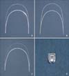
One of the active types of brackets, a self-ligation bracket (Clippy-C®) with a 0.022 slot, -7° torque, and 0° angulation for upper premolars, was used. Uncoated wires (Orthoforce®; G&H Orthodontics, Franklin, IN, USA) were used as the control group, polymer-coated wires (Dany coated arch wire; DANY BMT, Anyang, Korea) and rhodium-coated wires (Sentalloy® and White wire; Tomy Inc.) were used as experimental groups (Figure 1). For our study, we imployed three groups of wires: uncoated wires (control group); polymer-coated wires (P group); and rhodium-coated wires (R group). The wires used were 0.016-inch NiTi round wires and 0.017 × 0.025-inch stainless steel (SS) rectangular wires, and the angulations between the brackets and the wires were set to 0°, 5°, and 10° (Table 1).
Polymer-coated wires in the P group had limited coating in the anterior portion, unlike wires in the R group, which consisted of full rhodium coating on both the anterior and posterior portions. The full coating was utilized to improve the aesthetics in the anterior portion and for preventing changes in the wire thickness and frictional forces from affecting the posterior portion. However, to ease friction with the coating in a comparative experiment, we used full polymer-coated wires made to custom order that were not only coated in the anterior portion but also in the posterior portion.
Friction test
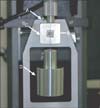
Each bracket was attached to the surface of the inner aluminum block (10 × 10 × 20 mm), which was custommade. After sandblasting the surface of the block, brackets were mounted on the middle of the surface using vertical and horizontal lines made with a adhesive material, Transbond (3M Unitek, Monrovia, CA, USA). The central part of the square space frame (10 × 10 mm) on the outer aluminum block (30 × 30 × 20 mm) was designed to be an exact match to the inner aluminum block and could be fixed with screws. The angles between the square framework of the outer aluminum block and the outline of the outer aluminum block were 0°, 5°, and 10°, and we were able to reproduce exactly the angle between the brackets and the wires using the combination of inner and outer blocks. The combination of these two blocks was inserted into the adjustable block, which was made to fit the table of the universal testing machine (Instron 5942; Instron Corp., Norwood, MA, USA).
The straight part corresponding to the posterior 5 cm cut on the upper arch of the wire was used in the experiment. The tensile test was set with a crosshead speed of 5 mm/min and the load cell had a range of up to 500 N; the wire was pulled through a distance of 5 mm, and we recorded and compared the maximum frictional forces and the static frictional forces by measuring the change in frictional forces as the wire moved across the distance (Figure 2).
We used two types of wires, 0.016-inch NiTi and 0.017 × 0.025-inch SS, in the three groups classified according to the type of coating, and set an angle of 0°, 5°, and 10° between the brackets and the wires. Each tensile test was repeated five times, and a total of 90 tests were completed for the 18 sets of samples. In the test with round wires, since a lower frictional force was expected, one bracket was used five times in the same group. In the test with rectangular wires, each bracket was used only once. The wires were used only once, and the tests were carried out by the same person.
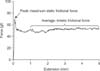
The maximum static frictional force was defined by measuring the maximum force at the initial extension, and the kinetic frictional force was calculated by averaging the frictional force while the wire was moved through 1 to 5 mm, for convenience (Figure 3).
Wire-surface tomography
The wire-surface tomography results, before and after the friction test, were compared for the two kinds of wires: the 0.016-inch NiTi wires and the 0.017 × 0.025-inch SS wires. We selected the wires set at an angle of 10° angle with the brackets. The wires were cut to pieces with lengths of 10 mm, including the 5 mm portion that was in contact with the bracket, and using with an ultrasonic cleaner. Scanning electron microscopy (SEM, Hitachi-800; Hitachi, Tokyo, Japan) was conducted to evaluate the morphology of the different wires.
Statistical analysis
After the maximum static frictional force was recorded and the kinetic frictional force was calculated, we determined the mean frictional force and the standard deviation of the frictional force. To analyze the effects of different types of wire coatings, the size and type of wires, and the angulations between the brackets and the wires, the frictional force were analyzed initially using a one-way analysis of variance and a Tukey's test with a 5% level of significance.
RESULTS
Comparison of maximum static frictional forces
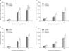
Comparison of maximum static frictional forces between the bracket and 0.016-inch NiTi wires with different coatings and angulations (Table 2, Figure 4A)
When the angles between the brackets and the wires were 0°, the maximum static frictional forces were not significantly different in all three groups (p > 0.05).
When the angles between the brackets and the wires were 5°, the maximum static frictional forces were not significantly different between the control group and the P group (p > 0.05), but they were significantly greater in the R group compared to the other two groups (p < 0.05). When the angles the brackets and the wires were 10°, the maximum static frictional forces were not significantly different between the R and P groups (p > 0.05), but they were significantly smaller in the control group compared to the other two groups (p < 0.05).
Comparison of maximum static frictional forces between the bracket and 0.017 × 0.025-inch SS wire with different coatings and angulations (Table 2, Figure 4B)
When the angles between the brackets and the wires were 0°, the maximum static frictional forces were not significantly different between the control group and the P group (p > 0.05), but they were significantly greater in the R group compared to the other two groups (p < 0.05).
When the angles between the brackets and the wires were 5°, the maximum static frictional forces differed significantly among the three groups (p < 0.05). The control group, P group, and R group had gradually increasing maximum static frictional forces (p < 0.05).
When the angles between the brackets and the wires were 10°, the maximum static frictional forces were not significantly different between the control group and P group (p > 0.05), but they were significantly greater in the R group compared to the other two groups (p < 0.05).
Comparison of kinetic frictional forces
Comparison of kinetic frictional forces between the bracket and 0.016-inch NiTi wire with different coatings and angulations (Table 3, Figure 4C)
When the angles between the brackets and the wires were 0°, the kinetic frictional forces did not differ significantly among the three groups (p > 0.05).
When the angles between the brackets and the wires were 5° and 10°, the kinetic frictional forces were not significantly different between the control group and the P group (p > 0.05), but they were significantly greater in the R group compared to the two other groups (p < 0.05).
Comparison of kinetic frictional forces between the bracket and 0.017 × 0.025-inch SS wire with different coatings and angulations (Table 3, Figure 4D)
When the angles between the brackets and the wires were 0°, the kinetic frictional forces were significantly different in all three groups (p < 0.05). The control group, P group, and R group had gradually increasing kinetic frictional forces (p < 0.05).
When the angles between the brackets and the wires were 5° and 10°, the kinetic frictional forces were not significantly different between the control group and the P group (p > 0.05), but they were significantly greater in the R group compared to the two other groups (p < 0.05).
Scanning electron micrographs of wires
We used scanning electron micrographs to examine the wires and compare their surfaces before and after the friction test. We observed many scratches on the wires after the test. Before the friction test, the surfaces of uncoated wire surfaces in the control group had fine scratches but were smooth on the whole. The wire surfaces in the P group consisted of small round adhesions. In the R group, the wire surfaces were not scratched, but there were rough protrusions. After the friction test on the 0.016-inch NiTi wires, depressions were observed on the surface in the control group, cracking of the coating was observed in the P group, and no notable changes were seen in the R group (Figure 5). Compared to the 0.016-inch NiTi wires, however, the 0.017 × 0.025-inch SS wires showed more pronounced changes on the surface resulting from the relatively larger amount of friction-induced surface damage. There was a severe depression on the wire surface in the control group, serious damage to the coating surface in the P group, and depressions on the surfaces of the R group (Figure 6).
DISCUSSION
Frictional force is the force that resists the relative motion of surfaces sliding against each other. One type of frictional force is the static frictional force that is present until movement starts, and the other is the kinetic frictional force that appears during movement. There is controversy concerning which frictional force is more significant in clinical orthodontic treatment. In the study by Drescher et al.,8 as the static friction and kinetic friction occurred at nearly the same time owing to the low crosshead speed of orthodontic tooth movement, distinguishing between the static and kinetic frictional forces was difficult. Frank and Nikolai9 used only the maximum kinetic frictional force because it was difficult to reproduce the kinetic frictional force in the oral cavity. In a study by Burrow,1 it was found that the static frictional force was more appropriate than the kinetic frictional force as orthodontic tooth movement is not continuous. On the other hand, Kusy and Whitley10 measured both static and kinetic frictional forces; Tselepis et al.11 used only the kinetic fictional force after the maximum static frictional force was reached because there was a constant alternating between the static and the kinetic frictional forces as the tooth intermittently slid and bound along the arch wire during orthodontic movements. In this study, the maximum static frictional force and the kinetic frictional force were measured because we believe that frictional values may vary for a given bracket-arch wire combination as the tooth moves along the arch wire in a tipping and uprighting fashion.11
The maximum static frictional forces and the kinetic frictional forces of the coated wires were equal to or higher than those of the uncoated wires, and there was a difference in the degree of change depending on the type of coating. The R group had the greatest frictional forces and the control group had the smallest frictional forces because the surfaces of the wires had different levels of roughness owing to the coating materials. The wires of the P group had an Ag coating for the white color and a Parylene membrane coating on the outer surface of the Ag layer. Parylene coatings had been used in many industries before being used for orthodontic wires. A parylene coating is generally known to be very robust, durable, and waterproof, have excellent chemical resistance, and exhibit less discoloration. It also has a great impact on the aesthetics because of its excellent light permeability and its non-toxic nature. Above all, the smooth membrane of a Parylene coating can reduce the roughness of the surface, and this is why the P group had lower frictional forces than the R group in our study. A rhodium coating is used on orthodontic wires because it is white, more aesthetic than other metals, and chemically stable because rhodium is a precious metal; it also has excellent wear resistance. However, the high surface roughness of rhodium produces greater frictional forces. In this study, the differences in frictional forces according to the type of coating were due to the direct influence of the polymer and rhodium in the coating. But we must consider the surface roughness as a characteristic of the material itself, and we need to take into account that corrosion, creep and relaxation, and the manufacturing processes (polishing, heating treatment, etc.) can affect the change in the resistance (corrosion, creep, and relaxation).9
We have to consider the changes in the thickness of the wire that result from the differences in the aesthetically superior materials that are used to coat the wire. Wires in both P and R groups had additional coatings on ready-made non-coated 0.016-inch NiTi wires and 0.017 × 0.025-inch SS wires, so fine increases in thickness appeared. In a study by Iijima et al.,12 the coating thickness in the R group was 10 µm, and so it did not affect the mechanical properties. DANY BMT, which manufactures the wires in the P group, explained that the changes in the wire thickness resulting from the additional coating of two polymer layers are less than 5 µm unilaterally and 10 µm bilaterally (Figure 7). However, the wires with polymer coating were thicker than the other two wires, as measured by digital vernier calipers that can measure lengths as small as 0.01 mm. The thickness of the polymer-coated 0.016-inch NiTi wires was 0.41 mm; the thicknesses of the uncoated wires and rhodium-coated wires were 0.37 mm; the thickness of the polymer-coated 0.017 × 0.025-inch SS wires was 0.42 × 0.62 mm; the thickness of the other two wires was 0.040 × 0.61 mm. Even if the wires were the same size like the 0.016-inch and 0.017 × 0.025-inch wires, different thicknesses, depending on the coating materials, could change the frictional forces by affecting the binding between the brackets and the wires. Consequently, we would need additional studies to elucidate the clinical significance of the changes in frictional force according to different coating thicknesses.
Changes in the frictional force according to the angle between the brackets and the wires are considered an important issue because in most cases, the orthodontic force acts at a slight angle rather than parallel to the brackets and wires during tooth movement. In a study by Kusy and Whitley,13 three components were found to affect frictional forces when the orthodontic wire slid. They were the static and the kinetic frictional forces, binding in the contact between the wires and the bracket's slot corner, and notching, which is a permanent deformation of the wires. In addition, the researchers suggested that the critical contact angle was 3.7°, which increased the frictional force rapidly as the brackets and wire were binding when a 0.016-inch wire was used with a 0.022-inch bracket slot. To evaluate the frictional force that resulted when the angle between the brackets and wires was changed to 0°, 5°, and 10° in this study, the angles used included critical contact angles.
Depending on the difference in angle between the brackets and wires, the maximum static frictional force and kinetic frictional force increased significantly in all cases as the angulations between the brackets and wires increased. The frictional resistance occurred at the bracket slot base when the angulation between the bracket and wire was calibrated at 0°. However, as the second-order angulations increased, frictional resistance occurred on the vertical planes of the bracket slot, as well as on its base. This additional vertical resistance increased the frictional forces. The frictional resistance increased rapidly when the angulation between the bracket and the wire was set at 5° because the critical contact angle was 3.7°. The frictional force also increased rapidly as the bracket and wire were binding if a 0.016-inch wire with a 0.022-inch bracket slot was used.13
The order of the groups regarding the values of the maximum static frictional force and kinetic frictional force was different when the angle was 10° between the brackets and the 0.016-inch NiTi wires. The maximum static frictional force was as follows: control group < R group = P group. The order for the kinetic frictional force was as follows: P group = control group < R group. The maximum static frictional force in the P group was greater than that of the R group, although the difference was not statistically significant. It is supposed that the degree of binding altered as the stiffness of the 0.016-inch NiTi wire changed according to the type of coating. It is believed that because the 0.017 × 0.025-inch SS wires was thick and less elastic, they exhibited different results compared to the 0.016-inch NiTi wires.
Using SEM, the different appearances of the surfaces of uncoated and coated wires could be observed. Surface roughness is the main factor that determines the frictional force, and our results showed that the R group had the roughest surface and the largest frictional force. It is considered that the frictional force was affected by the pattern and degree of coating damage during the friction test as well as by the surface roughness. Clinical studies show that coating damage can easily occur during tooth brushing or intake of food in the oral cavity, thus increasing the frictional force.
CONCLUSION
Coating materials continue to be developed to increase the aesthetics of orthodontic devices. The frictional forces of coated wires are equal to or higher than those of uncoated wires. However, the conditions in the oral cavity are very different from laboratory conditions because of the various tissues involved in oral functions, such as chewing, swallowing, and speaking, as well as the oral tissues that are in contact with the orthodontic appliance. Additional research on friction using conditions similar to those in the oral cavity will be needed to produce findings that have a clinically meaningful impact. In addition, to make the proper choice of coated wires, increased understanding of many factors such as abrasion resistance, discoloration, and compatibility with the teeth in the oral cavity, as well as frictional forces, is needed.


 XML Download