

 PDF
PDF ePub
ePub Citation
 Print
Print


INTRODUCTION
Three-dimensional (3D) imaging techniques are becoming increasingly popular and have opened new possibilities for orthodontic diagnosis and treatment assessment.1 In particular, maxillofacial 3D images can be obtained easily with the introduction of cone-beam computed tomography (CBCT) scanners.2 Although CBCT scan data provides abundant information, conventional 2-dimensional (2D) images, such as cephalograms, are still taken by most clinicians. Cephalograms are necessary for comparisons to earlier databases. Growth and treatment changes can be evaluated accurately only by obtaining sequential cephalograms.3
Farman4 stated that the "as low as reasonably achievable" (ALARA) principle of radiation exposure should also be used in CBCT images. To follow this principle, other 2D radiographs such as cephalometric radiographs should be generated from the CBCT data, although cephalograms are known to produce very low radiation. After Farman and Scarfe,5 several studies have addressed the generation of cephalograms from CBCT scan data. Moshiri et al.,6 Kumar et al.,7 and van Vlijmen et al.8 generated cephalograms using dry skulls for the materials in their studies. Kumar et al.9 and Cattaneo et al.10 performed in vivo comparison of CBCT-generated cephalograms with real cephalograms using living subjects. The results of all these studies, regardless of subjects, revealed that measurements from the CBCT-generated cephalograms are similar to those based on real cephalograms, and additional conventional imaging may be avoided when CBCT scans are acquired for orthodontic diagnosis. In particular, van Vlijmen et al.8 showed that the measurements on CBCT-generated images were superior in terms of reproducibility compared with those on conventional cephalometric radiographs.
In contrast, a literature review on this topic reveals a lack of consistency in head orientation when generating 2D cephalometric images from the CBCT volume rendering images. Although 3D measurements of CBCT volumes are free from the influence of patient position during image acquisition, the orientation of the secondary reconstruction of the volume directly affects the projection of anatomy in reconstructed 2D cephalometric images. The determination of head orientation is as important when measuring distances and angles on lateral cephalograms from CBCT images as it is in conventional cephalometry.11 Cevidanes et al.11 reported that the measurements on CBCT-generated images differ according to the head orientation, and emphasized the need for future studies to aid in the standardization of head position for CBCT acquisitions.
Recently, a novel device named Reference Ear Plug (REP), which mimics the ear rods in conventional cephalometry, has been developed, and its use is suggested when obtaining CBCT scans for orthodontic diagnosis.12 A titanium ball marker in each ear plug is represented on a 3D volume rendering image, in the same position as ear rods in conventional cephalometric apparatus. A virtual central ray can be set along the 2 markers represented on the volume image and used in the generation of 2D cephalogram images. The purpose of the present study was to evaluate the effectiveness of the use of REP during CBCT scan for the generation of lateral cephalograms from CBCT scan data.
MATERIALS AND METHODS
Thirty-three adults were enrolled in this study. Subject ages ranged from 24 to 29 years, and the exclusion criteria were severe skeletal disharmony or a developmental malformation of a craniofacial complex. All subjects provided informed consent to participate in this study, and the study was approved by the Institutional Review Board for Medical Science at Chonnam National University Hospital, Gwangju, Korea (I-2008-12-156).
Conventional lateral cephalograms were obtained using cephalometric X-ray equipment (OrthoCeph® OC100; Instrumentarium Imaging Ind. Co. Ltd., Tuusula, Finland). A photostimulable phosphor plate was used as the detector and positioned 150 mm from the midsagittal plane. The source-midsagittal plane distance was 1,500 mm. The plate was scanned at 650 dpi (Kodak DirectView CR975 system, Carestream Health, Rochester, NY, USA).
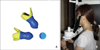
The CBCT scans were obtained with an Alphard Vega system (Asahi Roentgen Ind. Co. Ltd., Kyoto, Japan) under the following conditions: 80 kV, 5 mA, voxel size 0.39 × 0.39 × 0.39 mm, field of view 200 mm × 179 mm. Two CBCT scans were obtained for each subject separated by a 2-week interval. One was acquired using a conventional method, without REP, and the other was acquired with the use of REP. An ear plug, which contains a titanium ball marker 1.0 mm in diameter at its center, was inserted into each earhole of the subject, such that 2 ball markers were represented on 3D volume-rendering image. In the meantime, the head holders were positioned on the temporal area to fix the subject's head during the scan to eliminate motion artifact (Figure 1).
Generation of virtual lateral cephalograms from CBCT scans
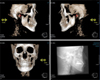
Two sets of volume data for each subject were exported in DICOM format to OnDemand3D™ software (version 1.0; CyberMed Inc., Seoul, Korea), 3D renderings were created, and virtual cephalograms were generated using the X-ray generator function of the software. For volume data obtained without the use of REP, virtual ray indicators in the program were located at the porion, which is the most superior point on the roof of the entrance to the ear canal. The indicators on both sides were positioned in the same anatomical area, rendering the resultant virtual ray to be similar or parallel to the central ray in a cephalometer. In the case of volume images taken with the use of REP, each virtual ray indicator was positioned in the titanium ball represented on each side of the head image. Virtual cephalograms were generated by perspective projection using the soft ware. Camera to film distance and Ear rod to film distance were set at 1,650 mm and 150 mm, respectively. Generated cephalograms were stored in DICOM format to permit their importation into cephalometric analysis software (Figure 2).
Measurements and comparison of virtual cephalograms with real cephalograms
For each subject, one real cephalogram and 2 virtual cephalograms were imported into V-ceph™ software (version 4.0; CyberMed Inc., Seoul, Korea). Sixteen landmarks listed in Table 1 were selected, and 13 linear and 16 angular measurements commonly used in conventional cephalometric analyses were calculated using the software.
Statistical analysis
In order to assess the method errors (MEs), the images from 20 subjects (10 men and 10 women) were selected randomly, and the landmarks were identified twice at an interval of 2 weeks by a single investigator. The MEs of the double registration of all landmarks were calculated using Dahlberg's formula13 as follows:
where d is the difference between the 2 measurements and n is the number of subjects. The MEs ranged from 0.11 mm to 0.43 mm in linear measurements and from 0.20° to 0.52° in angular measurements.
The linear and angular measurement accuracy was de monstrated by the means, mean differences, and absolute mean differences between each pair of real cephalogram and virtual cephalogram measurements. To compare measurements from virtual cephalograms generated with or without REP with those from real cephalograms, a paired t-test was used for each measurement after verifying normality by the Shapiro-Wilk test. Statistical evaluations were performed at the 5% level of significance with SPSS software (version 17.0; SPSS Inc., Chicago, IL, USA).
RESULTS
Table 2 shows the discrepancy in linear measurements between each virtual cephalogram and real cephalogram. Virtual cephalograms generated with REP differed less from real cephalograms compared to the virtual cephalograms generated without REP. The differences between the real and virtual cephalograms generated with REP ranged from -0.09 mm to 0.30 mm, whereas the differences ranged from -0.77 mm to 1.85 mm in the case of virtual cephalograms generated without REP. Additionally, when the discrepancies were calculated in absolute values, the differences for virtual cephalograms generated with REP ranged from 0.24 mm to 0.63 mm, whereas the differences for virtual cephalograms gene rated without REP ranged from 0.52 mm to 2.08 mm. The results of paired t-test indicated statistically significant differences in 8 of 13 measurements in the comparison between the real cephalograms and virtual cephalograms generated without REP. In contrast, no measurements demonstrated significant differences between the real and virtual cephalograms in the case of CBCT scan data obtained with REP (Table 2).
Table 3 shows the discrepancy in angular measurements and comparison between the real and virtual cephalograms. Similar to the linear measurements, no angular measurements demonstrated statistically significant differences between the real and virtual cephalograms generated with REP, whereas one measurement, saddle angle, significantly differed between real cephalograms and virtual cephalograms generated without REP. The magnitudes of differences between the real and virtual cephalograms were also greater in the case of virtual cephalograms generated without REP. In particular, articular angle, gonial angle, Frankfort mandibular incisor angle (FMIA), and interincisal angle differed by values greater than 2.0°. In contrast, the differences from real cephalograms were less than 0.9° in the case of virtual cephalograms generated from CBCT scans with REP (Table 3).
DISCUSSION
It has been reported that measurement accuracy is not influenced by the subject's head position in 3D measurement of CBCT images. Hassan et al.14 investigated the influence of head position on the accuracy of linear measurements on 3D surface-rendered images and reported that measurements based on 3D surface images are accurate, indicating no influence of head position on the measurement accuracy of CBCT images. Although 3D measurements of CBCT volume images are free from the influence of patient position, the orientation of the volume image affects the projection of anatomy in 2D images generated from CBCT scan data. Cevidanes et al.11 demonstrated that measurement reliability could differ according to virtual head orientation in their study of CBCT-generated cephalograms. They further reported that head orientation in CBCT images may also affect the relative anatomical location, and maintained that head orientation is important for diagnosis and treatment planning. They suggested the need for future studies to aid in the standardization of head position for CBCT scans.
In the present study, REP was used to standardize the orientation of CBCT images. Titanium ball markers were used to form a virtual central ray for the generation of 2D cephalograms. Because the REPs were inserted into the earholes during the scan procedure, the virtual central ray is highly similar to the real central ray in a cephalometer. In other words, the generated images would be the same as the real cephalometric images. Although the program includes 2 options, parallel and perspective projections, perspective projection was used in this study, because real cephalograms are made with perspective projection. In clinical settings, either parallel or perspective projection can be used depending on the case. However, perspective projection should be used if the generated image must be compared with earlier cephalograms taken previously.
Some scanners have ear rods as a component of the head holder, as in a cephalometer. The scanner used in the present study also has ear rods. However, the ear rods were not inserted into the earholes, but instead used to fix the subject's head. When the ear rod in the scanner was inserted into the ear canal with sufficient pressure to immobilize the head, the patient felt discomfort. Therefore, the ear rod was positioned on the temporal area to fix the subject's head during the scan to eliminate motion artifact. The REPs were inserted into the subject's earholes comfortably, and served as the reference for the virtual central ray used to generate 2D cephalograms.
Whereas the present study regarding cephalogram generation was aimed to reduce ionizing radiation by eliminating the necessity of taking additional radiographs, 2 CBCT scans were performed for each subject in the research, with and without the use of REP, which was necessary to avoid possible bias in the investigation. Although CBCT scan is reported to produce very low radiation compared to medical multi-slice CT, the need to reduce possible biological effects of ionizing radiation was considered.15,16 For this reason, the 2 scans were obtained on different dates, separated by a 2-week interval, in this study. It should be taken into consideration not only in clinical settings but also in research that low-dose examination should be performed for the sake of radiation hygiene.
The comparison between the real and virtual cephalograms showed that many measurements, particularly linear measurements, showed significant differences from real cephalograms in the case of CBCT scans without REP. Eight of 13 linear measurements presented significant differences, with mean differences ranging from 1.08 mm to 2.08 mm. Although many previous studies on CBCT-generated cephalograms have maintained that they can be used in clinics, their conclusions were based on the study of reproducibility, not on ac curacy. The results of this study indicate that CBCT-generated cephalograms without the use of the REP may be suitable for diagnosis of a new patient, but not in the evaluation of growth and treatment changes compared to earlier real cephalograms. In fact, Grauer et al.17 demonstrated that variability should be taken into account when the CBCT-generated and real cephalograms are used within the same longitudinal study in their investigation of the systematic differences and landmark errors between the 2 image modalities. They concluded that the error due to the combination of the 2 modalities might be larger than that previously estimated.17
Interestingly, only one angular measurement significantly differed between real and virtual cephalograms generated without the use of REP whereas many linear measurements demonstrated significant differences. Regarding the projection errors of angular measurements in conventional radiographs, Ahlqvist et al.18 demonstrated that rotations within ±10° of the modeled angles give rise to angle distortion of less than ±0.6°. Yoon et al.19 reported that the projection errors of angular measurements of lateral cephalometric radiographs did not exceed a difference of 1% at all rotational angles regardless of the direction of angle, and were far less than those of the linear measurements. The influence of different head position on measurement accuracy is likely to be less sensitive in case of angular measurements. However, this fact does not necessarily mean that angular measurements can be used without a problem in clinics or for research. The values of mean differences between the real and virtual cephalograms were large: 3.03°, 2.06°, 2.54°, and 3.09° for the articular angle, gonial angle, FMIA, and interincisal angle, respectively. These levels of difference would be of clinical significance, although they were not statistically significant differences. In contrast, the differences between the real and virtual cephalograms were small in the case of CBCT scan with the use of REP, ranging from 0.20° to 0.90°.
Although significant differences occurred in many measurements in the case of CBCT scan without the use of REP, no significant differences were seen in any measurements when CBCT scanning included the use of REP. This finding indicates that 2D cephalogram images can be accurately generated from CBCT scan data. As suggested previously,20 all conventional radiographic images can be replaced with one CBCT scan, which provides not only 3D information that cannot be obtained with 2D images, but also generates 2D images to simulate conventional radiographic images, such as cephalograms, if data is obtained with the use of REP.
When the virtual ray indicators are positioned on the right and left side of head images to construct a reference axis for the generation of a 2D cephalogram image from CBCT scans without the use of REP, much time and attention is required to locate the same anatomical area on both sides of the image. In contrast, the procedure was simple and much faster in the case of CBCT scans with REP. This was certain even without an inclusion of additional research regarding elapsed time.
While REP was used for 2D image generation in this study, its application would also enable orientation of the 3D volume image in a standardized position. Standard orientation of the volume image would further contribute to accurate diagnosis, particularly in patients with dentofacial deformity, including facial asymmetry. The use of REP is therefore highly recommended for accurate 3D evaluation as well as 2D image generation.
CONCLUSION
The discrepancy between the real and virtual cephalograms showed smaller values in the case of CBCT scan with REP compared to scan without the use of REP.
In the comparison of the real and virtual cephalograms, no measurements demonstrated significant differences in the case of CBCT scan with REP, whereas many measurements significantly differed in the case of CBCT scan without REP.
Thus, the use of REP is suggested during CBCT scan in order to construct accurate virtual cephalograms using 3D CBCT images.


 XML Download