

 PDF
PDF ePub
ePub Citation
 Print
Print


INTRODUCTION
Model surgery prior to orthognathic surgery is a routine procedure for purposes of diagnosis and treatment planning in patients with dentofacial deformity. Although a variety of appliances and techniques have been introduced to date, limitations such as difficulty in equipment operation and inaccuracy have also been reported.1-5 Potential errors in model surgery are caused by improper mounting of models, errors in reference line placement, and errors in measuring the displacement of segments. Particularly in the case of bimaxillary surgery, repositioning of the maxillary cast in the planned location is extremely difficult, making it a primary cause of errors.6 Because the surgical wafer is made from the repositioned cast, model surgery is the most important procedure to ensure that the actual surgery is performed accurately.
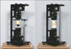
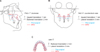
To improve accuracy and reduce errors during model surgery, Jeon et al.7 developed a 6-axis model surgery simulator, which enables implementation and application of rigid body motion dynamics to the model surgery, and reported its accuracy (Figure 1). The simulator, called Jeon's orthognathic surgery simulator (JOSS), was improved and patented. A rigid body, introduced to easily describe phenomena of dynamics, refers to an ideal object whose body is not deformed or destroyed under any external force. Most solids that are not broken under any very strong force are considered rigid bodies.8 Once an object is defined as a rigid body, since the relative location of every point of the object is fixed, every motion is determined by translation and rotation of the specific point of the rigid body. Translation in the longitudinal (anterior-posterior), vertical (upward-downward), and lateral (left-right) directions and rotation on longitudinal, vertical, and lateral axes are referred to as longitudinal translation, vertical translation, lateral translation, roll, yaw, and pitch, respectively, which comprise 6 degrees of freedom (DOF) (Figure 2).9
When maxillary and mandibular models mounted on the JOSS are considered as rigid bodies and their state of motion is described in a quantitative manner, precise locational information can be shared. The aim of this paper is to propose a new chart to share the locational information of a maxillary model during the model surgery, the Jeon's model surgery chart (JMSC), and present a new method used with the simulator in clinical applications.
DIAGNOSIS AND ETIOLOGY
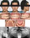
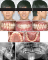
A 22-year-old man with Class III malocclusion was referred to our clinic with complaints of facial deformity and chewing difficulty (Figure 3). Upon extra-oral examination, prominent chin and facial asymmetry caused by the shifting of the mandible to the right side were observed (Figure 3). Intra-oral examination revealed anterior crossbite combined with a 2-mm shift of the mandibular midline and missing maxillary right central incisor (Figure 3). Cephalometric analysis indicated a Class III skeletal relationship, flat occlusal plane, and labioversion of the maxillary central incisors (Figure 3 and Table 1).
TREATMENT OBJECTIVES
Bimaxillary surgery was chosen to correct the prognathic mandible and facial asymmetry. To correct the flat occlusal plane, labioversion of maxillary central incisors, and concavity of facial profile, rotational surgery of the maxilla, setback surgery of the mandible, and malar augmentation were planned. Crown and bridge treatment for the maxillary right central incisor was planned after orthodontic treatment.
TREATMENT PROGRESS
Preoperative orthodontic treatment and surgery planning
Paper surgery
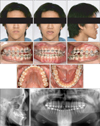
After preoperative orthodontic treatment (Figure 4), paper surgery was performed on a lateral cephalogram, and, based on its result, the pitch (7 degrees, clockwise) of the maxillary model and amount of vertical (1 mm, upward) and longitudinal translation (2 mm, backward) of the midpoint of two centers of incisal edge of two maxillary central incisors (MPIE) were determined. Next, paper surgery was performed on a posteroanterior (PA) cephalogram, and based on its result, the amount of roll (4 degrees, clockwise) and lateral translation (0 mm) of the MPIE were determined. Finally, computed tomography was used to determine the amount of yaw (0 degrees) (Figure 5).
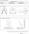
Creation of Jeon's model surgery chart
The amount of movement in each of the 6 DOF was determined during the paper surgery and recorded. To indicate a direction, numeric figures were marked at the tips of direction arrows. Rotational motion values were recorded in degrees, and translational motion values were recorded in mm. The actual amount of translation should be calculated considering the magnification of cephalograms. If no movement occurs, its value should be marked as 0 (Figure 6).
Mounting of dental models
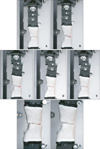
Commutable joints are available that allow compatibility with various types of facebows on the right and left vertical portion of the main frame. In this case, the spring facebow of the Hanau Modular Articulator System 192 (Whip Mix Co., Fort Collins, CO, USA) was used (Figure 1A). A magnetic detachable cast support and anterior round metal rod were substituted for the cast support and mounting platform, respectively, of the Hanau system (Figure 1A). After attachment of the facebow to the JOSS, the remaining mounting procedures were performed in almost the same manner used for general articulators. One difference is that the JOSS opens and closes the space between the dental cast and mounting plate by vertical translation, not swinging the upper portion of the articulator. After mounting was complete, the horizontal plane of the JOSS was equal to the patient's Frankfort horizontal (FH) plane (Figure 7A).
Yaw and roll correction
The maxillary model was moved vertically 10 mm upward to prevent the mandibular model and wax bite from interfering with the maxillary model movement (Figure 7B). A 0-degree turn was executed to correct yaw, and a 4-degree turn was performed to correct roll, as recorded in the JMSC.
Pitch correction and return of the MPIE to original location.
To obtain the planned occlusal plane angle, the pitch stage operated a 7-degree turn (Figure 7C). After 3 types of rotational motion were completed, the MPIE was displaced compared to its pre-surgical state. This unwanted displacement of the MPIE caused by yaw, roll, and pitch correction should be moved back to its pre-surgical position through operation of the 3 translational stages MPIE. Wax indentation on the bite fork of the facebow, putty mass recording of the pre-surgical inter-incisal relationship, or pre-surgical wax bite can be used as a reference point of the pre-surgical position of the maxillary inter-incisal tip. In this case, a pre-surgical wax bite was used. The 3 translational stages were operated until the changed MPIE contacted its indentation in the wax bite. The outcome of this process had an identical result to displacement of the maxillary cast rotated on the MPIE (Figure 7D).
Longitudinal, lateral, and vertical translation
After returning the MPIE to its pre-surgical position, the 3 planned translations of the MPIE were performed. When 3 types of translation stages executed the inter-incisal edge translation recorded in the JMSC, movement of the maxillary model was completed in accordance with 6 DOF (Figure 7E).
Fabrication of the interim wafer
The mandibular model-attached stage was translated 15 mm downward, and a resin separator was applied to both the maxillary and mandibular model. Monomer of self-curing acrylic resin and polymer were mixed together, and when this mixture reached dough-like consistency, it was placed on the occlusal surfaces of the mandibular cast. Then the mandibular model was returned to its original position. Shape correction was performed before curing, and after curing, the mandibular model was translated downward to remove and trim the interim wafer.
Orthognathic surgery
Le Fort I osteotomy was performed; the maxillary alveolar process was completely mobilized and repositioned as planned. The amounts of rotation and translation were confirmed by interim wafer. Bilateral sagittal split osteotomy was then performed. Mandibular setback and malar augmentation of 10 mm on the right side and 12 mm on the left side were performed (Figure 8).
Superimposition of surgical treatment objective (STO) and actual results of surgery
Lateral and PA cephalometric radiographs and panoramic radiographs were taken after surgery. STO performed on pre-operative film was superimposed onto postoperative film (Figure 9); 0 degrees of yaw, 3 degrees of roll, 6 degrees of pitch, 0 mm lateral translation, 2 mm backward translation, and 0 mm vertical translation were measured.
Postoperative orthodontic treatment
Postoperative orthodontic treatment continued for 8 months. A fixed 3 × 3 retainer was attached to the mandibular arch for retention, and the fixed orthodontic appliances were removed. A circumferential removable retainer containing a resin pontic tooth for the upper right central incisor was delivered to the upper arch. Crown and bridge treatment of the maxillary right central incisor was performed after 3 months of debonding.
RESULTS
The patient's facial profile significantly changed after bimaxillary surgery. Prognathic mandible and concave profile were corrected. Class I canine and molar relationships were well maintained. Superimposition of pre- and post-treatment lateral cephalometric radiographs showed that the planned FH-occlusal plane angle, upper central incisor-to-FH angle, and repositioning of MPIE were almost obtained (Figure 9A and Table 2). However, slight facial asymmetry remained due to insufficient roll correction during actual surgery (Figure 9B). Skeletal relapse did not occur over a 1-year follow-up period (Figure 10).
DISCUSSION
Diverse model surgery techniques and appliances have been introduced to enhance clinicians' accuracy and reproducibility.10-17 Ideal model surgery must not be erroneous in itself at any stage of the manipulation, and at the same time, it must be easily performed and highly reproducible. It must be accepted by clinicians with ease based on their background knowledge and facilitate communication among clinical specialists in a cost-effective and less time-consuming manner. Furthermore, 3-dimensional movement of the model must be intuitively visualized without going through separate measuring procedures, and in the event of errors or changes in treatment planning, return to the previous step of the surgery should be possible with a simple adjustment.
When model surgery is performed for orthognathic surgery, maxillary and mandibular models should be regarded as a rigid body. Since the relative location of each part of the rigid body is predetermined, designation of movement (in mm) for more than 2 points within the rigid body is contradictory. In other words, designating movement of the inter-incisal edge tip of the maxillary central incisor as well as the mesiobuccal cusps of both first molars (on both sides) will introduce mechanical contradiction and prevent realization of the planned movement in 3 dimensions. In accordance with the concept of 6 DOF, explaining mechanical movement is possible only when translation for one point is determined based on 3 dimensions and described using yaw, roll, and pitch.
To perform model surgery based on the aforementioned concept, Jeon et al.7 developed the JMSC and JOSS, confirmed their accuracy, and reported that the use of these methods in model surgery achieved precise realization of the planned outcome. The JOSS is beneficial not only by enhancing the accuracy of movement, but also by permitting the control of one movement among the 6 DOF separately. The existing translation method using manual adjustment allows simultaneous movement in more than 2 DOF over 3 dimensions. Although movement with only 1 DOF is desired, unwanted movement occurs concurrently, thus harming the accuracy of the model surgery and wasting substantial time. However, the JOSS is equipped with 6 stages that control 6 DOF independently, so it can exclude unwanted degrees of freedom. Therefore, it can considerably shorten the time necessary for model surgery.
It is advantageous not only because the saw-cutting procedure of the plaster model can be omitted, but also because the process is simple to undo. In the existing method, in which a maxillary model moves through plaster cutting, clinicians must wait until the plaster connecting an articulator with the plaster model has completely dried and perform additional procedures for moving and fixing. Additionally, when errors or changes to a treatment plan occur, the entire procedure must start again from facebow transfer. However, when model surgery is conducted using the JOSS, the surgery can be performed immediately after the plaster on the connecting portion hardens. Furthermore, in the event of errors or changes to the treatment plan, clinicians can set the stage to zero to immediately return procedures to the pre-surgical state. Finally, because graduations are marked on the fixed and moving units of stages, clinicians can move models and simultaneously identify the amount of movement.
Using the JMSC enables surgeons, orthodontists, and dental technicians to share accurate and objective information. Thus, application of the JMSC to an interdisciplinary treatment apporaches where many clinicians of different specialties may be engaged should accompany collaborative research and discussion for better utilization of the JMSC. Errors in model surgery using JMSC and JOSS may be caused by overlooking the magnification of cephalograms or improper returning of the MPIE to pre-operative position. Future studies should be conducted to obtain more conclusive information about these errors.
CONCLUSION
Use of the JMSC and JOSS will promote accurate communication about model surgery among clinicians based on objective measurements. Our study proposes a new method of communication of treatment plan, model surgery, and wafer fabrication, and these findings indicate a promising area for future research and collaboration.


 XML Download