

 PDF
PDF ePub
ePub Citation
 Print
Print


INTRODUCTION
Lingual orthodontics, a more esthetic orthodontic technique than labial orthodontics, has developed rapidly in recent years.1-3 Many case reports and papers have documented the treatment effects, and a variety of bracket designs have been produced.4,5 The disadvantages of lingual orthodontics include the excessive chair time, complicated biomechanics, patient discomfort, expensive lab procedures, and high material prices.6,7 However, several innovations have improved the use of lingual orthodontics, such as customized lingual brackets and 2-dimensional lingual brackets that can be bonded directly.8,9 Nonetheless, the efficient control of anterior torque and intrusion during retraction continues to be a limiting challenge.
Mini-screws and mini-implants (the osseointegrating type) have been successfully applied to lingual orthodontics.9,10 Mini-implants placed on each side of the palate have been used to avoid uncontrolled tipping and the deepening of the anterior bite during en masse retraction. Typically, the treatment protocol involves the soldering of a lever arm to the main lingual arch wire.10,11 The lever arm moves the force vector apically and closer to the center of resistance, thereby allowing better control of torque during retraction. One disadvantage of this mechanics is that play within the slot allows some of the torque to be lost during retraction. In addition, if bilateral mini-implants are not in the same horizontal plane, which is sometimes required by the anatomy of the maxilla, the clinician may see unwanted canting of the occlusal plane due to different force vectors generated during retraction. Moreover, the sliding mechanics in a full-arch appliance using mini-implant-assisted anterior retraction may be adversely affected by friction within bracket slots and tubes, causing unwanted distalization of posterior teeth.
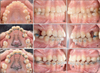
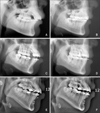
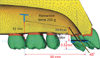
Several recent reports12,13 have introduced "lingual bio creative therapy" into lingual orthodontics. This new treatment system allows en masse retraction of the anterior teeth independently of the posterior teeth by using a C-retractor and palatal miniplate (Figures 1 and 2). The C-retractor is constructed by soldering a 0.9-mm stainless steel wire onto mesh-bonding pads and is subsequently bonded to the lingual surfaces of the 6 or 8 anterior teeth.14 Unlike typical bracket/arch wire setups, slot play is not an issue in this type of setup. Furthermore, the C-retractor is adequately rigid to resist deformation under a normal retraction force. This particular feature facilitates control of the axes of the anterior teeth during retraction of the anterior segment. Also, selection of the appropriate vertical height of the lingual anterior retraction hooks (LARHs) allows the clinician to produce controlled tipping, bodily movement, and lingual root movement during retraction (Figure 3). Patient compliance is unnecessary, and patient comfort is improved when compared to lingual brackets.
For cases in which the upper second premolars are affected by certain conditions (e.g., dilacerated roots, short roots, compromised teeth, or dens invaginatus), extraction of the second premolars is usually indicated, even though the goal of lingual biocreative therapy is maximum anterior retraction. In a previously cited clinical study,12 miniplates in the palate (C-plates; Jin Biomed Co., Bucheon, Korea) were the only source of anchorage for the en masse retraction of the 6 or 8 maxillary anterior teeth. No appliances were placed in the upper and lower posterior dentitions. The C-plates were designed to have adjustable extension wings to allow the clinician to alter the force vectors. Further, the C-plate is fixed to the cortical bone of the maxillary palate, and a flap does not need to be laid. Hence, damage to the roots of adjacent teeth or anatomical structures is not a concern. Since the applied orthodontic forces during anterior retraction are against the C-plate and not against orthodontic appliances fixed to the posterior teeth, no change in the posterior occlusion is expected during retraction.12,13,15 To date, however, no studies have analyzed the force systems involved in the control of anterior torque and intrusion by this technique, with the exception of studies in clinical literature and case reports.
The aim of this study was to use finite element analysis (FEA) to evaluate the effectiveness of anterior segment retraction using the C-plate while varying the vertical height and location of the C-retractor hook.
MATERIALS AND METHODS
Construction of the base finite element model
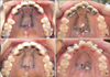
We obtained tooth outlines by performing three-dimensional (3D) laser scanning of a right maxillary tooth from a dental study model of the normal adult dentition (Nissin Dental Products Inc., Kyoto, Japan). We aligned and leveled the dental arches using a broad arch form (Ormco, Glendora, CA, USA) and referred to previous studies to assign inclination and angulation.16,17 Neither a curve of Spee nor a curve of Wilson was added (Figure 4). The thickness of the periodontal ligament was assumed to be uniform (0.25 mm).18 The alveolar bone crest was constructed to follow the cemento-enamel junction (CEJ) curvature 1 mm apical to the CEJ. The 3D-finite element model included 12 teeth, an open space to correspond to the missing first premolars or second premolars, periodontal space and alveolar bone. The model was also bilaterally symmetrical. In the finite element model, the teeth, alveolar bone, and periodontal spaces were constructed with fine tetrahedron solid elements, and node-to-node contact elements were installed between adjacent teeth to represent tooth interactions. In this study, the teeth, alveolar bone, and periodontal spaces were assumed to be isotropic and homogeneous linear elastic bodies, and the material properties of the elements were based on values for Young's modulus and Poisson's ratio, according to previous studies (Table 1).19-21 In the system studies, we assignedd the X-axis to the median-lateral direction, the Y-axis to the anterior-posterior direction, and the Z-axis to the coronal-apical direction. Furthermore, we defined +X as the left central incisor direction, +Y as the labial (anterior) direction, +Z as the apical direction, and the X - Y plane as the occlusal plane of the teeth. In all cases, we assumed no movement of the posterior teeth, since they received no force application.
C-retractor
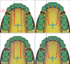
To fabricate the C-retractor, a 0.9-mm stainless-steel round wire (this round wire is a 2-noded, 3D beam element that has 3 transitional and 3 rotational degrees of freedom and can represent the bending characteristics of wires) was formed passively along the lingual surfaces of the upper anterior teeth. Afterwards, an additional wire was used to construct the lever arm hook, which was connected to the C-retractor by node sharing. The wire system was connected to stainless steel pads (tetrahedron solid element) by node sharing as well to complete the appliance (Figure 4). The C-retractor was adjoined to the lingual surfaces of the upper anterior teeth at 5.5 mm apical to the incisal edge of the maxillary central incisor by node sharing. Four experimental conditions were used in this study, and were based on the teeth extracted and the placement of the LARHs. The maxillary first premolar extraction cases were conditions 1 and 2, while the second premolar extraction cases were conditions 3 and 4. The LARH position between the maxillary central and lateral incisors comprised conditions 1 and 3, while LARH placement between the lateral incisors and canines made up conditions 2 and 4 (Figure 5).
FEA and tooth displacement graphs
The LARHs were constructed close to the surface of the palatal rugae, and the element analysis was implemented for each case using different vertical heights (1, 4, 7, 10, and 13 mm) for the LARHs. The vertical height was measured from the plane of the mesh-plate to the end of the hook perpendicular to the occlusal plane. In clinical studies, the retraction force was applied from the C-plate; however, in this FEA study, the C-plate model was not included in the analysis, and was therefore not fabricated. This reduced complications in the analysis. Using the usual position and dimensions of the C-plate as a reference, the hooks extending laterally from the C-plate were laterally 8.2 mm from the mid-palatal suture, sagitally located between the upper first and second molar, and 12 mm apical to the common lingual bracket position. A retraction force of 200 g was applied to each side (Figures 4 and 5).
The tooth displacement was marked by applying the X, Y, Z coordinates at the midpoint of the incisal edges of #11 and #12, the cusp tip of #13, and the corresponding root tips.
The FEA was performed using ANSYS 11 (Swanson Analysis System, Canonsburg, PA, USA), the universal finite element program, on an HP-XW6400 workstation (Hewlett-Packard Co., Palo Alto, CA, USA).
This study was approved by Institutional Review Board of Yeouido St. Mary's Hospital.
RESULTS
Tooth displacement pattern on the Z-axis
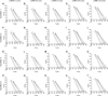
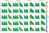
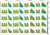
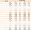
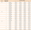
Two hundred grams of retraction force was applied to the C-retractor hook under the 4 conditions described in the Materials and Methods section. The results of the relationship between the tooth displacement pattern on the Z-axis (the plus [+] and minus [-] symbols refer to intrusion and extrusion, respectively) and the vertical height of the LARH are shown in Table 2 and Figures 6 and 7. For condition 1, the incisal edge of #11 and the cusp tip of #13 were intruded using the LARH vertical heights of 10 and 4 mm, respectively. The degree of extrusion was greater for condition 2 than for condition 1 at the same LARH height. For condition 2, the incisal edge of #11 and the cusp tip of #13 were intruded at the LARH vertical heights of 13 and 10 mm, respectively. The results for conditions 3 and 4 were similar to those for conditions 1 and 2, respectively; however, the amount of tooth displacement under conditions 3 and 4 were reduced relative to conditions 1 and 2.
Tooth displacement pattern on the Y-axis
For condition 1, a retraction force of 200 g resulted in lingual and uncontrolled tipping of the maxillary central incisor crown when the LARH vertical height was 1 mm (Table 3, Figures 6 and 8). Controlled tipping was observed at the LARH vertical heights of 4 and 7 mm, while bodily displacement and the occurrence of root retraction was noted at the LARH vertical heights of 10 and 13 mm. For condition 2, the degree of the lingual tipping of #11, #12, and #13 increased in comparison to condition 1 at the same LARH vertical height. For condition 2, the maxillary central incisors at the LARH vertical heights of 7 and 10 mm showed controlled tipping, while actual root retraction was observed with the LARH vertical height of 13 mm. The pattern of tooth movement was similar between conditions 1 and 3, but bodily displacement for condition 3 was observed at a lower vertical height of 7 mm. Meanwhile, a similar pattern of tooth displacement was found between conditions 1 and 4, but bodily movement in condition 4 was observed only when the vertical height was more than 10 mm.
DISCUSSION
In lingual orthodontic treatment, the attachment and removal of lingual brackets are technique sensitive, and thus challenging and time consuming. Because of these issues, these proceudres may involve a complex and expensive set-up process. Moreover, routine adjustments and archwire fabrication require expertise, experience, and technical skill. As a result of these challenges, some clinicians choose expensive technology to facilitate the process. For instance, in cases in which the treatment of anterior protrusion requires maximum anchorage, complicated overlay archwires and/or mini-implant anchorage have been recommended to achieve controlled 3D tooth movement.22 The lingual biocreative therapy applied in this study is a method to retract the anterior dental segment using forces between the C-retractor and the C-plate. The biomechanical premise underlying segmental orthodontics is adapted from one of Burstone's protocols,23 but differs in that the force is applied to a segment from a skeletal anchor with no connection to the posterior teeth. Extended lever arms have been used in conventional lingual orthodontics for retraction against mini-screw-anchors, but torque loss is a common side effect due to slot play within the appliance as well as flexibility of the archwire. Biocreative therapy with the C-retractor eliminates these side effects, because the anterior segment is bonded as a unit with a rigidly constructed device. Furthermore, retraction control is in the hands of the clinician, since controlled bodily displacement, tipping, and root retraction is possible through altering the vertical height of the LARH.24,25
The results of the current study are similar to those of the FEA study of Jang et al.,26 which used a modified C-retractor and various miniscrew positions. In that study, the optimal choice for vertical height of the LARH was found to be related to the goals for retraction (i.e., controlled tipping, bodily displacement, root retraction). The device was bonded to the lingual surfaces of the upper 6 or 8 anterior teeth, and retraction was implemented by applying a closed NiTi coil spring between the extension hook of the C-plate and the LARH of the C-retractor. In the current study, 3D tooth displacement was controlled by varying the vertical height of the LARH. Our results were different from those of a previous clinical study to control torque,27,28 as well as the study by Mo et al.,29 which attempted 3D tooth movement through the control of intrusion and retraction in a labial treatment method. The latter study showed differences between the control of the incisors and canines, but found that only variation of the vertical height of the LARH provided the desired 3D control during retraction of the anterior teeth.29 One of the potential reasons for this difference between the previous report and the current one may be the rigidity afforded by the C-retractor. The 0.9-mm wire is much stiffer than a standard archwire placed in conventional lingual brackets. Future studies may show this rigid C-retractor to be valuable when applying heavy retraction forces, as in the case of perisegmental corticotomy for inducing rapid tooth movement.13,30
In the current study, the retraction pattern depended on the position of the LARH. Although both positions met the requirements of controlling the upper incisor axes and preventing deepening of the bite, the position for conditions 1 and 3 (between the maxillary central and lateral incisors) had more significant treatment effects for the same vertical height than that of conditions 2 and 4 (between the lateral incisors and the canines). One advantage of using the LARH position in conditions 1 or 3 is that the canine can be segmented from the C-retractor, allowing detailing of the canine while still retaining incisor retraction with the C-plate (Figure 9). Therefore, we recommend that as a rule of thumb, the LARH should be placed distal to the central incisors rather than distal to the lateral incisors.
This study examined the initial displacement due to orthodontic forces, using the FE method. Hence, further studies on the clinical long-term effects, the retraction pattern, and the risk of root resorption for lingual biocreative therapy using the C-retractor and C-plate will be needed. In addition, we anticipate further studies on the design and treatment effects of C-retractors in asymmetrical premolar extraction cases.
CONCLUSION
The following conclusions can be made on the basis of the findings in this study:
1. FE studies have demonstrated that variations in the vertical height of the LARH affect the vector of the retraction force and produce measurable effects on the inclination and vertical position of the anterior teeth during anterior retraction.
2. The LARH can be placed between the central and lateral incisors or between the lateral incisors and canines. Placement distal to the central incisors was considered preferable because the treatment effects were better. If the LARH is distal to the lateral incisors, a vertically higher hook is necessary to achieve bodily displacement.


 XML Download