

 PDF
PDF ePub
ePub Citation
 Print
Print


INTRODUCTION
The recent improvements in socioeconomic conditions have led to an increased interest in aesthetics among adults, and this trend has resulted in an increased demand for orthodontic treatment. However, patients hesitate to begin orthodontic treatment because of several factors, including the unaesthetic nature of and discomfort due to the conventional fixed orthodontic appliances as well as the fear of the associated pain. These issues can be addressed by using lingual orthodontic appliances and clear aligners,1,2 but these devices have limitations. Lingual orthodontic appliances are difficult to use for maxillary alignment in patients with deep overbite. Further, clear aligners have limited indications and make the application of light continuous force difficult.3
To date, orthodontists have primarily focused on brackets for aligning teeth. We seek to avoid this rigid view and implement treatments that are simpler yet allow the appropriate application of orthodontic force. Here, we describe the treatment of mild anterior crowding, including palatally displaced lateral incisors, by using a minimally invasive method with light force applied via nickel-titanium (Ni-Ti) wire segments and tubes instead of the conventional brackets.
DIAGNOSIS AND ETIOLOGY
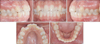
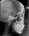
A 25-year-old woman presented at the clinic with a chief complaint of maxillary anterior crowding. At the initial examination, her facial profile was satisfactory, but 3.5 mm of maxillary anterior crowding was observed, with the maxillary midline displaced approximately 1 mm to the right. The overbite and overjet were both 1 mm. Both maxillary lateral incisors were directed palatally, resulting in crossbite. Slight mandibular anterior crowding was also seen. The patient had a stable posterior occlusion (Figure 1). Cephalometric analysis revealed skeletal Class I malocclusion (ANB = 3.0°). The long axis of the maxillary incisors was within the normal range but was slightly upright. Meanwhile, the long axis of the mandibular incisors was within the normal range (Figure 2).
TREATMENT OBJECTIVES
The patient accepted non-extraction partial orthodontic treatment of the anterior maxilla, accompanied by interproximal reduction (IPR). We decided to minimize the use of the conventional fixed orthodontic appliances and employed a less bulky and more aesthetic appliance for applying light continuous force.
TREATMENT PROGRESS
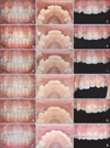
We determined the final positions of the maxillary teeth via a working model for diagnostic set up which indicated that approximately 2 mm of IPR would be required (Figure 3). The first step was to create a space for the displaced lateral incisors. Passive wires were bonded to the canines and premolars to serve as an anchor. Next, Ni-Ti springs formed by bending 0.012-inch straight Ni-Ti wires was bonded with orthodontic adhesive resin proximal to the canines and central incisors bilaterally (Figure 4). Stripping was performed between the central incisors (Figure 5A-5C).
The midline space closed after 1 week, and lingual retainers were attached to both central incisors. One month later, as sufficient space was regained, we began aligning the left lateral incisor. To avoid possible occlusal interference, we decided to intrude the tooth by approximately 1.5 mm. For the intrusion, a 0.008-inch ligature wire was attached to the Ni-Ti spring originally used for regaining the space, allowing the elasticity of the latter to produce an intrusive force on the lateral incisor (Figure 5D-5F). Approximately 2 months later, intrusion of the left lateral incisor was achieved and sufficient space for the right lateral incisor was regained; therefore, we initiated its intrusion by using the same method (Figure 5G-5I).
After sufficient intrusion of the left lateral incisor, at 4 months from the beginning of the treatment, stainless steel round tubes with a diameter of 0.64 mm were bonded for tooth alignment according to the working model (Figure 5J-5R). A month later, a lingual retainer was attached to the left anterior region, which was aligned first, to use as an anchor for the right-side alignment.
During the orthodontic treatment, the right second premolar had to be restored. The width of the provisional restoration was decreased by about 0.5 mm to regain space for the right lateral incisor. In addition, 2 mm of IPR was performed, spanning from the mesial surface of the left first premolar to the mesial surface of the right first premolar. We achieved right-side alignment by the same method as for the left side.
RESULTS
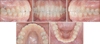
Approximately 8 months from the beginning of the treatment, we debonded all the attachments. The clinical outcome is shown in Figure 6.
Model superimposition was performed to assess the tooth movement (Figure 7). This method showed that the tips of both the maxillary lateral incisors had shifted labially by approximately 3.0 - 3.5 mm. The intrusion at their final positions was approximately 0.5 mm.
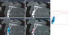
Superimposed pretreatment and post-treatment cone-beam computed tomography images were used to evaluate changes in the root positions (Figure 8). The superimposition revealed that both the lateral incisors, which had been inclined palatally, now had the appropriate axes of teeth within the alveolar bone because of the precise diagnostic set up and the application of light force.
DISCUSSION
In the present case, a working model for diagnostic set up was used for analysis and alignment was planned with 2 mm of IPR from the mesial surface of the maxillary left first premolar to the mesial surface of the contralateral first premolar, allowing slight flaring. Passive wires bonded in the posterior region, which showed stable occlusion, served as the anchors for the anterior alignment.
The conventional brackets and open-coil springs are commonly used to regain space for lateral incisors. However, their bulk and exposed surfaces can be problematic, and excessive spacing with unwanted tooth movement (not fail-safe) can occur if the patient does not visit the clinic for a prolonged period. In the present case, a working model was created to help regain the necessary space without the unnecessary tooth movement. Light continuous force was applied by using a small round Ni-Ti wire (0.012 inches), allowing the teeth to shift without patient discomfort. In addition, the wires were bent toward the gingival line; this masking of the wire was aesthetic, minimized bulkiness, and decreased patient discomfort.
Palatally displaced lateral incisors are typically extruded. The crossbite must be corrected without occlusal interference during alignment. Occlusal interference associated with such extrusion can prevent proper tooth positioning, and therefore, the temporary use of a bite plate may be necessary.4 However, unnecessary bite raising may occur when a bite plate is used in adults, and the patient discomfort due to such an appliance cannot be ignored. Park et al.5 achieved alignment in such cases by intruding the lateral incisors using tubes without additional appliances and minimizing occlusal interference during the correction of crossbite. In our case, sufficient intrusion to avoid occlusal interference was achieved by using only the wire for regaining space between the central incisors and the canines. Afterward, we positioned the lateral incisors properly by using tubes.
Because the root position of palatally displaced lateral incisors may be more palatal, additional labial root torque is often required, even after alignment. In our case, the initial root position was labial and additional torque was not needed, because the teeth were aligned through adequate uncontrolled tipping (Figure 8).
CONCLUSION
In this adult female patient with mild anterior crowding, including palatally displaced lateral incisors, tooth movement predicted on the basis of a working model was accomplished without the conventional brackets. Tooth alignment was achieved efficiently and aesthetically by using light force, a minimally invasive method, and a minimal number of compact devices.


 XML Download