

 PDF
PDF ePub
ePub Citation
 Print
Print


INTRODUCTION
Conventionally, basal bone has been assessed by measuring the apical third of a root or through measurement of a specific distance from the gingival margin to the mucogingival junction (MGJ) on dental casts.1,2 Recently, however, virtual models have been considered a feasible alternative to plaster models due to their accuracy.3,4 Previous studies evaluated the relationship between dental and basal arch forms using the WALA (acronym for Will Andrews and Larry Andrews, who proposed a band of soft tissue immediately superior to the mucogingival junction) ridge on virtual models,5-7 but soft tissue thickness, which varies among teeth, may affect the WALA point positions.8
Cone-beam computed tomography (CBCT) has come to replace traditional 2-dimensional (2D) radiographs in current practice. Numerous studies have documented the accuracy and reliability of CBCT-derived images.9,10 Tai et al.11 evaluated dental and skeletal dimensions using CBCT before and after application of a Schwartz appliance. Bayome12 evaluated the relationship between dental and basal arches with 3-dimensional (3D) virtual models and CBCT images in normal occlusion subjects.
Several studies have evaluated arch dimensions in different malocclusion samples.13-15 However, few have compared the dental and basal arch forms of Class I and III subjects. Slaj et al.16 investigated the dental arch dimensions in different malocclusions and found larger intercanine and intermolar widths in Class III subjects when compared to Class I or II subjects. Furthermore, Braun et al.17 reported that dental arches associated with Class III malocclusion were wider than those of Class I. The mandible of Class III cases may demonstrate a wider variety of relationships between the dental and basal arch forms compared to normal occlusion samples.
So far, dental casts or virtual models have been used to investigate dental and basal arch forms in different skeletal classes, but no CBCT evaluation of the relationship between dental and basal arch forms in normal occlusion and Class III malocclusion has been reported. Therefore, the purpose of this study was to investigate the relationship between mandibular dental and basal arch forms in subjects with normal occlusion and for comparison with Class III malocclusion subjects using CBCT.
MATERIALS AND METHODS
CBCT images of subjects with normal occlusion and Class III malocclusion were selected for this study. The normal occlusion group, consisting of 32 dental students (19 males, 13 females), served as a control group and was selected from a sample pool of 480 students from Wonkwang University, Iksan, Korea. Their ages ranged from 19.1 to 34.6 years (mean age, 24.3 years). They were classified as having a skeletal and dental Class I relationship; ANB angle of 0° to 2° and canine and molar Class I relationship.
For the Class III malocclusion group, which served as the experimental group, 33 patients (20 males, 13 females) were selected from a sample pool of 301 patients from Seoul St. Mary's Hospital, The Catholic University of Korea. The ages ranged from 16.9 to 39.5 years (mean age, 22.2 years). These patients were diagnosed with skeletal and dental Class III malocclusions, with an ANB angle of less than 0° and Wits value of less than -4 mm. Exclusion criteria for both groups included (1) missing or decayed teeth; (2) dental restorations that altered tooth size, shape, or location of the midpoint of the clinical crown; (3) prosthetic crowns or gingival defects; (4) arch length discrepancies greater than 3 mm crowding or 1 mm spacing; (5) facial asymmetry with unilateral or bilateral crossbite. Institutional Review Board approval for this study was granted by the Catholic Clinical Research Coordinating Center of Catholic University of Korea
CBCT images of the head and neck of the normal occlusion group were acquired using the VEGA system (Asahi Roentgen Ind. Co. Ltd., Kyoto, Japan) with a 200 × 179-mm field of view, 80 kV, and 5 mA, resulting in 0.39-voxel resolution. CBCT images of the Class III malocclusion group were obtained using an iCAT scanner (Imaging Science International, Hatfield, PA, USA). The scanning parameters were 120 kV, 47.7 mA, 20 s per revolution, and a 170 × 130-mm field of view. These settings resulted in a voxel size of 0.4 mm. Each subject's head position was oriented so that the Frankfort plane was parallel to the floor in a seated position, and images were taken at the intercuspal position.
The CBCT data were exported in digital imaging and communications in medicine (DICOM) multi-file format and imported into InVivo5.1 software (Anatomage, San Jose, CA, USA) for 3D volume rendering. All measurements were made by the same operator (K.E.S). Reorientation of the head position of each scan was performed. The contact point between the mandibular central incisors (MCI) was selected as the origin of the X, Y, and Z coordinates. Then, the image was rotated so the transverse reference plane (X-axis) coincided with the occlusal plane, which connects the mesiobuccal cusp tip of the right and left mandibular first molars and the origin. The midsagittal plane (Y-axis) was defined by passing a line through the MCI and parallel to the anterior and posterior nasal spines. The vertical plane (Z-axis) was perpendicular to both X and Y axes in which the right, anterior, and superior directions were positive.
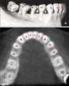
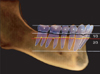
The anatomical reference points, the facial axis (FA) points18 and root center (RC) points, were identified from the left to right first molar. The RC points were digitized at the center of the root on a transverse section parallel to the occlusal plane at the level of the coronal third of the right and left canine roots. This level was selected to correspond to the vertical level of the WALA point,19 which is located at the most convex point on the MGJ, directly below the FA point and perpendicular to the occlusal plane (Figures 1 and 2).
The coordinates of digitized points were then exported into Microsoft Office Excel 2007 (Microsoft, Redmond, WA, USA). Distances between the FA and RC points for each tooth were then calculated. Four linear and 2 ratio variables were measured and calculated for each arch form (Table 1). The best-fitting curves of mean FA and RC points for normal occlusion and Class III groups were constructed to illustrate arch form differences between the groups. The X and Y coordinates for the mean FA and RC points of each group were inputted into mathematical software (Matlab® 7.5 [R2007b]; The MathWorks Inc., Natick, MA, USA) to generate the best-fitting curve that represented the arch using the fourth degree polynomial equation:
To evaluate the intra-operator reliability of the FA and RC point identification, 30 randomly selected CBCT images from both groups were re-digitized 2 weeks later by the same examiner. Intraclass correlation coefficient (ICC), using a 2-factor mixed effect model and consistency as type, showed high reliability for dental (ICC ≥ 0.97) and basal measurements (ICC ≥ 0.95).
Statistical analysis
The dental and basal arch dimensions and the mean distances between the FA and RC points at each tooth were compared between normal occlusion and Class III groups by independent sample t-test. The correlation between the basal and dental intermolar and intercanine widths was evaluated by Pearson correlation independently in each group. p-values < 0.05 were considered statistically significant.
RESULTS
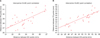
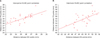
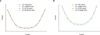
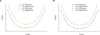
Dental and basal intercanine widths were the only dimension that significantly differed between normal occlusion and Class III groups. For Class III subjects, the dental and basal intercanine widths were 30.13 and 25.44 mm, significantly larger than their normal occlusion counterparts, which were 28.67 and 23.76 mm, respectively (p < 0.05) (Table 2). In the normal occlusion group, strong positive correlations were found between intercanine dental and basal widths (r = 0.71; p < 0.001) as well as between intermolar dental and basal widths (r = 0.76; p < 0.001) (Figure 3). In the Class III malocclusion group, moderate correlations were found between the intercanine dental and basal widths (r = 0.60; p < 0.001) as well as between the intermolar dental and basal widths (r = 0.62; p < 0.001) (Figure 4).
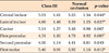
The distances between FA and RC points significantly differed between the 2 groups at each tooth except for the canines (Table 3). Best-fitting curves of the mean FA and RC points for both groups indicated that the differences were mainly in the anterior region, with the Class III arches appearing larger than the normal occlusion arches (Figure 5). The curves of the dental and basal arch forms for each group demonstrated different arch shapes as well (Figure 6).
DISCUSSION
Understanding the relationship between the dental and basal arch forms is of diagnostic and therapeutic importance because expansion of the dental arch is limited. Negative iatrogenic effects, such as dehiscences, have been reported as a complication in the anterior alveolar bone after retraction of the anterior teeth.20 However, no method devised to date permits accurate determination of the basal arch form.
Recently, the relationship between dental and basal arch forms has been reported in Class I and II malocclusions.5,6 However, no similar study has been conducted with Class III patients using CBCT imaging or 3D virtual models. Therefore, our study evaluated the relationship between dental and basal arch forms in subjects with normal occlusion and III malocclusion using CBCT imaging and compared the 2 groups. It would have been better if the same CBCT machine had been used in acquiring the data for both groups. Although there is no difference in magnification in the resulting CBCT images, subjective image quality can vary between machines.21
Interestingly, most studies conducted on the basal arch form suggested using landmarks located on the alveolar bone rather than the basal bone.5-7,22-24 Thus, the term "basal arch" used in these studies, including ours, is a misnomer. Nonetheless, this basal arch, or more accurately "alveolar arch," may be of more significance to clinical practice than the anatomical basal bone, since the alveolar process is the enclosing structure of the teeth.
With the advent of CBCT, a new landmark, i.e., RC, was defined to assess the basal arch on CBCT images.12 The RC point corresponds to the WALA point, but is lo cated inside the basal anatomical structure, and it approximates the center of resistance of each tooth. Therefore, the basal arch may be more accurately expressed using this landmark rather than the WALA points on a virtual model. In addition, digitization of an anatomical landmark such as the root apex to identify the basal arch may be unreliable due to high variability in position and shape of the respective tooth. Hence, a constructed landmark such as the RC point may increase the reliability of results while accurately representing the basal arch form. The high associated radiation dose is a major disadvantage of CBCT. However, a recent study reported that for some CBCT machines, the effective dose could be as low as triple the dose of a dental panoramic view.25 Nevertheless, the benefits of CBCT imaging should be weighed against the radiation dose separately for each case.
In our study, RC points were digitized on a single trans verse section at the level of the coronal third of the canine roots, because applying separate transverse sections at the center of resistance of each tooth would not allow for consistent basal arch form. Also, since the average root length of mandibular teeth ranges from 12.6 to 15.9 mm,26 the maximum difference in the length of one-third of a root, approximately 1.0 mm, is negligible (Figures 1B and 2).
Recently, Slaj et al.16 evaluated dental arch dimensions on 3D models and reported larger intercanine and intermolar widths and depths in Class III malocclusion subjects when compared to Class I and II malocclusion cases. However, in our study, only intercanine dental and basal widths were significantly larger in the Class III group. As shown in Figure 5, best-fit curves showed differences mainly in the anterior region. This inconsistency may be due to differences in the methodology and landmarks employed in these studies.13,15,16
The best-fitting curves for the dental and basal arches of the Class III group demonstrated square-like arch forms (Figure 6). This finding is supported by previous studies reporting that the transverse dimension of Class III subjects is wider than that of Class I or II subjects.13,15,16 The dental and basal intercanine and intermolar widths demonstrated strong correlations in the normal occlusion group and moderate correlations in the Class III group. This finding suggests that the dental arch form corresponds to the basal arch form more strongly in normal occlusion than in Class III malocclusions, sup porting the "apical base" theory that the dental arch form is initially shaped by the configuration of its supporting bone, which limits dental arch expansion.7 Recognition of the dimensions and shapes of the dental and basal arch forms, as well as their relationship, may help clinicians to accurately position teeth during treatment and preserve patients' arch forms, which could in turn lead to more stable and predictable treatment outcomes.
Our results may be useful for clinicians to better understand the relationship between dental and basal arch forms in normal occlusion and Class III malocclusion patients. The stability of the treatment outcome may be questionable without consideration for the relationship between the dental and basal arch. In addition, evaluation of the dental and basal arch dimensions in different Angle classifications should be followed by assessment of the different shapes of these arch forms, for example tapered, ovoid, and square. Previous studies demon strated different arch form distributions among different ethnic groups.27-29 Therefore, evaluation of the basal arches of different arch forms in different ethnic groups is recommended. Moreover, our relatively small sample size made it difficult to stratify the Class III group into mild, moderate, and severe cases; however, to achieve a homogenous group, all subjects in the Class III group were surgical cases. The effect of the severity of malocclusion on the basal arch form should also be evaluated. Additionally, further study is needed to determine whether anatomical landmarks other than RC points could serve as an even more accurate representation of basal bone. Finally, an investigation of the different types of basal arch forms is required.
CONCLUSION
Our findings from this CBCT study are summarized as follows.
The dental and basal intercanine widths were significantly larger in Class III subjects than in normal occlusion subjects.
Dental and basal arch widths were strongly correlated in the normal occlusion group and moderately correlated in the Class III group.
These results might be helpful for clinicians to have a better understanding of the importance of basal arch form in the alveolar bone.


 XML Download